Week 3: Computer controlled cutting
This week I worked with concepts (2D), coreldraw (2D), solidworks (3D), and Fusion 360 (3D) for producing projects on the vinyl cutter and laser cutters.
Goals for Computer Controlled Cutting
- Use vinyl cutter to produce hazard decals for my SLA resin station
- Use laser to produce curing station for my SLA resin station
- Design custom decal for office window ~with atleast 3 layers~
- Characterize laser cutters per group assignment
-
Design custom construction kit (dog-feed-sign) per individual assignment - ~Introduce living hinges or compliant mechanisms. A hardwareless laser-cut hinge would also suffice~
~ are stretch goals ~
Decal Production
Practice with multi-layer decals
For an intro into decal production, I watched Nidhie use her workflow. She also directed me to this tutorial they share with students. This workflow involves:
- Coreldraw for importing bitmaps and converting to vectors
- Sillouette studio for preparing the prints
- S2 vinyl cutter for cuting the decal
- Transfer tape for producting multi-layer decals and transfering the decal to the final resting place.
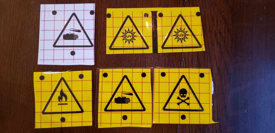
My first goal was to produce 4 hazard decals for my upcoming resin printing journey. Documentation of that journey will be found here. Resin printing is extremely hazardous and therefore I need these four decal types:
- (x2) UV light exposure - printer and cure station
- Corrosive liquid - resin
- Toxic gass - VOCs in air
- flamable liquid - IPA at wash station
- Alien abduction - test print and for the lulz
I started by finding a high resolution image that included many common danger symbols.

Finding this image above took a few iterations. Mostly because I found out the hard way, Corel does not like files that look like below. This is a png that was downloaded as a jpg, and therefore the “transparent” background is captured into the actual image. This checkerboard is difficult to clear out using the trace feature. This is not an uncommon result when using google images. We’d rather have a simple jpg with a white background, which will trace easier.

I imported the good source image into corel draw and traced the bitmap by using Trace bitmap -> outline trace - > detailed logo. This allowed me to pull out the background color. I attempted to reduce the # of colors in the document to 2 using the colors tab. At first this route caused me trouble, because it processed nearly-alike colors as different. Eventually, Tom Dubick pointed out the merge function which allowed me to combine colors, reduce the # of colors in the image down to two (yellow and black), and remove unwanted colors such as white. This process required a few iterations
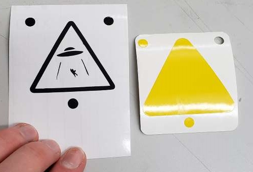
Then I used right-click -> ungroup all objects to be able to individually separate the symbols from eachother and their backgrounds. I like the symbols I’ve gathered here, but want to search for a cleaner decal yellow background. Therefore I downloaded a clean UV decal with a higher resolution yellow triangle. Using the trace bitmap -> colors tab, I was once again able to pull out many of the colors as well as merge some of the like-colors. Then I was left with the outer triangle shape.
I attempted to fill the inner triangle to no avail. Nidhie pointed out that the inner triangle was actually being treated like a curve. By right clicking on the curve and hitting “break curve apart”, I was able to completely fill in the triangle.
I then scaled my symbol objects to be like size and used the fill tool to ensure they were the same color.

I then positioned each one-by-one over the template, saving just the black elements as separate png files. I also saved the yellow triangle on its own as a png. The export function makes this process easy. I am finding import/export are the best functions for bringing files in and exporting files our in Corel. Avoid the open function for instance. These full-size files are available in my github repo here under files/week03.
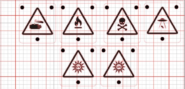
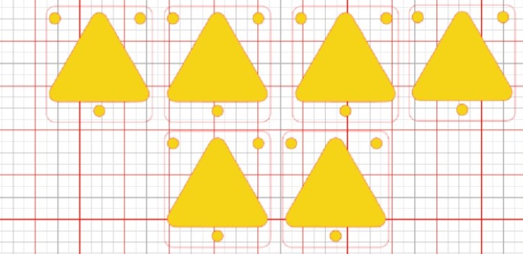
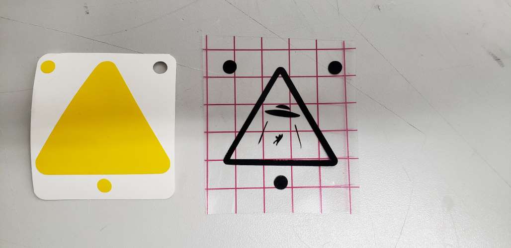
Then came time to load my designs into sillouette studio. Upon dropping them in, the only issue was scale. I had to resize both the layers the same amount. I settled on decals that were 2” tall. Then, I followed Nidhie’s instruction by adding square outlines around each decal to make peeling them easier. Additionally, I added the 3 registration circles as reference points to properly line up the yellow/black layers. Using the trace outer layers function, sillouette is able to recognize all of the edges to be cut, which are then displayed as thin red lines (see below). Finally, I separated the layers into different files since they will be cut in separate operations.
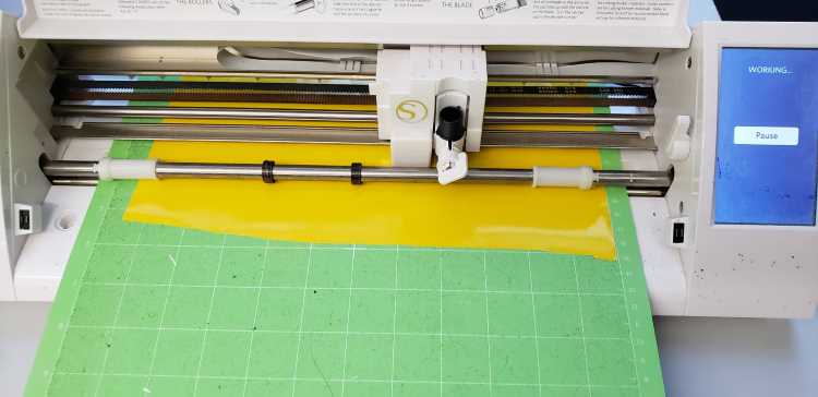
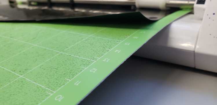
I then cut out, stuck the appropriate decal sheets to the cutting mat. I then loaded the mat in the machine using the load mat button on the touch screen. The decal side faced up while the backing faced down. I ran each of them through.
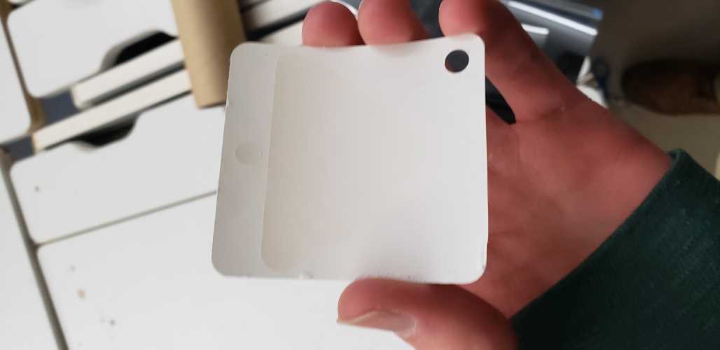
While cutting the black sheet, I learned a few things the hard way. First, the edges of the decal began to peel up.
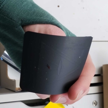
This was easily resolved on my next run by adding some blue painters tape to the corners. Then, I found out that I wasn’t actually cutting decal matertial. I had actually pulled out “iron-on” decal, which is not appropriate for the decals I was hoping to make. As you can see below, this material has no backing to peel off.
After cutting the proper material, I found that some of the lines were cutting too deeply and in some cases, cutting all the way through the backing. This was suitable for now, but the vinyl cutter blade and settings should be looked at in future projects. Test cuts would be a good first step going forward.
The last error I discovered was during the weeding process. Weeding is the process directly after printing of removing parts of the decal we don’t want. During this process I found that especially small elements such as the alien abduction rays and registration marks tended to move during weeding.

Later I found out from Neil that weeding is best done once the decal has been moved to another substrate. Weeding off of the backing is frowned upon, because as I found out the hard way, nothing wants to stick to the backing. Once these issues we’re worked through, I was left with two weeded layers.
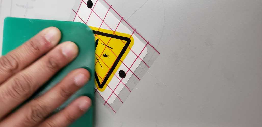
Then came time to combine them using transfer tape. This process is done top-layer down. So first I laid transfer tape over the black layer and smoothed it over with the smoothing tool. Then I removed the backing, being careful to pull at a shearing angle. Here is the result
This transfer tape is then laid over top the bottom layer, being careful to line up the registration marks.
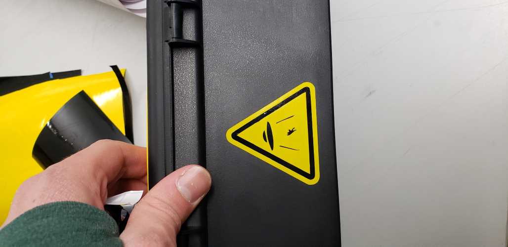
Then I am left with a good decal, protected between the backing and transfer tape. Finally, this can be applied to your surface of choice. In my case, a toolbox holding my electronic components (aka space magic).
This process was then repeated for the reast of the hazard decals. By then, I had been instructed to weed off of the transfer tape rather than the original backing. Much better results.
Class Decal Production
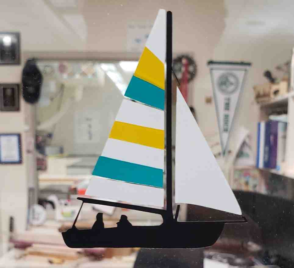
Then it came time to produce a sticker to go on Mr. Dubick’s window, as is tradition. Circling back to my goals, I wanted it to use atleast 3 colors. An unwritten stretch goal of mine was for it to be personal, custom, and something that would ‘leave my mark’ on the lab, so to speak.
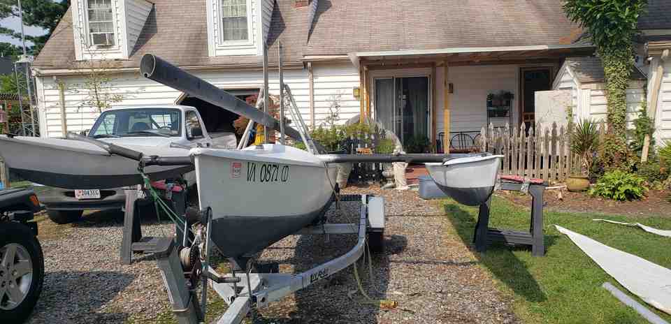
As such, I settled on a sailboat. Better yet, to make it sailboat, I wanted to roughly match the color scheme of my 20’ Trimaran. That is, white, yellow and blue for the sails and black as suitable for the hulls, lines, and mast (see below).

I started with a stock silhouette of a sail-boat, being sure to select one that was open-source. Also, having learned from my earlier excercise, I was sure to find one with relatively simple shapes and thicker elements.

The next step I took was to remove the background using my typical Gimp workflow and the Color to Alpha command.
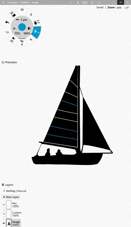
I then loaded this image into the Concepts windows app, which is a stylus friendly 2D vector program. More on this program can be found on my week 02 page here. It allows me to customize the image, remove elements I don’t want, and maintain features such as quality, transparency, and vectorness (definitely a word). First priority was to clean up the shape of the hull and remove the rather messy looking water pattern. Then,to separate elements into separate shapes, I used the stylus eraser with a smoothing setting turned to high. For instance, this allowed me to make the sail independent (not-touching) the mast and boom. I wish I had remembered to do the same for the front sail, more on that later. Lastly, I separated the sail into its different sections with smooth straight lines. I would have gone ahead and filled these sections, but the Fill tool in Concepts is unique and time-consuming.
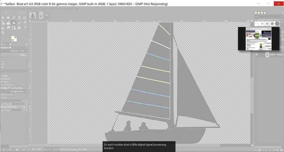
To fill these zones, I wanted to load into a bitmap program such as Gimp. For whatever reason, Gimp seemed to crash upon trying the Fill Bucket.
Next I tried CorelDraw. In hindsight, I should’ve probably gone to microsoft paint to stay in the bitmap world until those zones we’re filled. But I went to Corel and Traced the images. This gave me separate “curve” objects for each of the different regions, and one for the black elements.
Using the Object Manager and the Eyedropper Tool, I was able to Fill the different curves with the correct colors. It was also useful to hide the curves themselves and only show the filled zones. Finally, I was able to then drag the zones to be perfectly adjacent and desirable shapes.
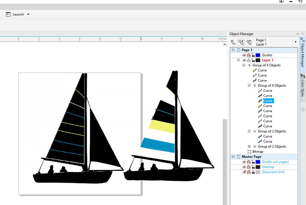
This method worked up until the top portion of the mainsail and the foresail. These curves/zones we’re still connected to the elements I wanted black. At this point I had a fight with CorelDraw, and was unable to make these elements independent curves, despite _Ungrouping__ and disconnecting them completely. At this point, Tom Dubick asked the all important question. What are you trying to do? It was at this point I realized that I was simply trying to fill in the different zones. A function that could be done perfectly done in a simple bitmap program such as Paint3D. These troublesome portions we’re finished off in Paint3D, which is where I should have been in the first place (if not Gimp).

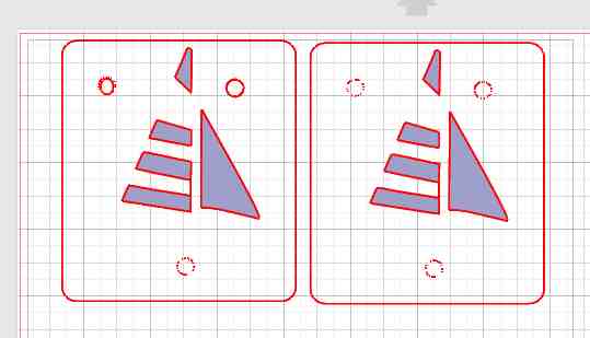
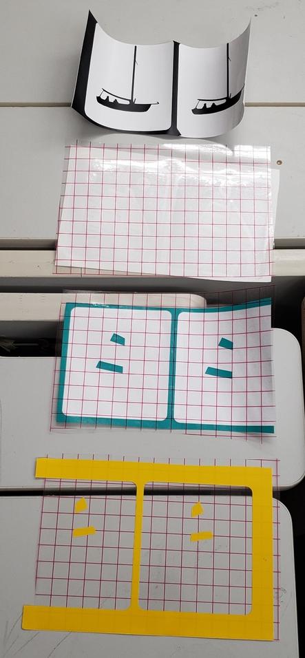
Then it was time to Import into CorelDraw, and trace the different regions based on color. By showing/hiding the desired regions, I was able to export the different zones independtly, with the goal of importing them separately into Silhouette Studio. The only issue with this method seems to be scale. In the future, it would be great to find a workflow that maintains scale when going from Corel - > Silhouette. Because my current workflow has me scaling each layer independently which is time consuming and could lead to error. I then stacked each layer in Sillouette Studio, being sure to line up the registration marks which we’re drawn in Corel.
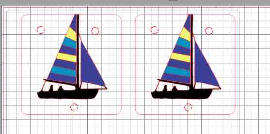
After tracing these elements with Silhouette’s Trace tab, I was then able to isolate the different colors into different Silhouette workspaces by deleting all the rest. Then after printing each layer, hitting undo several times to bring the rest of the colors back. Surely there is a better workflow here too.
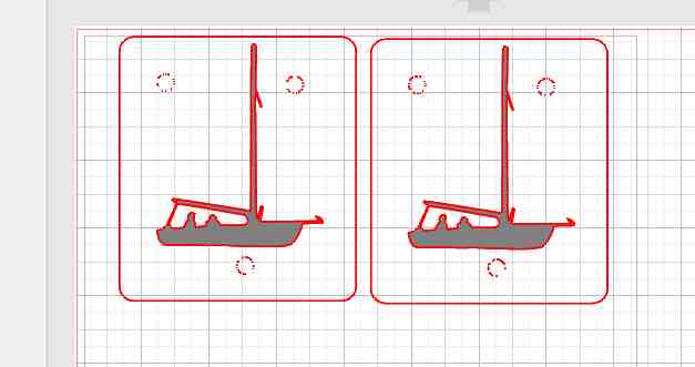
One these we’re printed, the weeding process began. At this point, I realized the hard way that the registration marks did not trace correctly. Therefore, they came off with the weeding in most cases. In the future, I will draw these directly in Silhouette as opposed to Corel. I then transferred everything to transfer tape.
It would have been better to work top-layer down, transferring each layer to one piece of transfer tape. That said, I already had all layers on transfer tape, and they were missing registration marks. Therefore, the best option at this point was to transfer each layer directly to the final substrate (the office window).

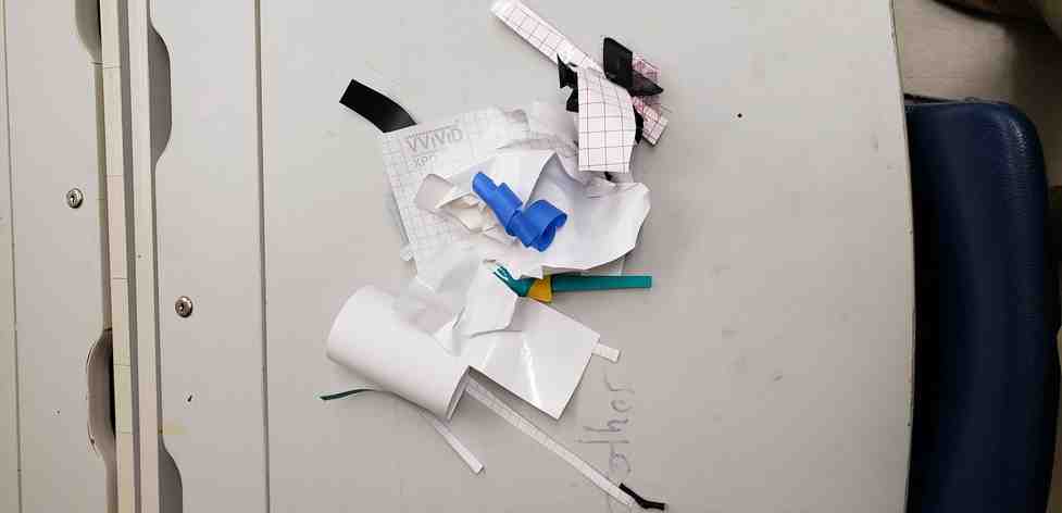
An aside about waste
This is probably as good a time to talk about waste products when making things. I noticed that by area, my efficiency in producing this sticker was probably less than 2%. That is to say,
^^ (Final Sticker Area) ^^   is less than 2% by eyeball
   (Total Material Area)
In other words, it used quite a bit of waste.
I believe something keeping me from learning to “fail-fast” and break things, is my aprehension towards waste. But this is when I had a small eureka moment. If my prototyping is going towards building products that will eventually be mass-produced, then any failures/waste now could prevent massive waste at the production level. Put another way, any waste now, pales in comparison to the potential waste from bugs that make it into the production and market phases. It may not seem like much, but this shift in perspective will help me going forward.
Cure station production
CAD Model Creation and Render
Originally, I began this project during the CAD week which can be found here.
Having since learned a lot about solidworks and designing for laser cutting, I have decided to revisit the project, starting from near scratch.
Crucially, I wanted to be able to change the “Sheet Thickness” as a variable and have the changes propogate through the whole design. One recurring issue for Solidworks is I cannot seem to create variables at the assembly level and use them at the part level. Detailed discussion of this topic here, but these solutions did not work for me. This was the last straw for me. As much as I want to learn Solidworks, I am even more interested in creating awesome projects. I’ve spent too much time fighting with Solidworks. It’d be one thing if these we’re rare occasions or simply a case of I have never done something before. No, these are cases where I know exactly what I want to do and the software makes it convoluted and forums seem to only suggest workarounds. To top it all off, while trouble shooting this, Solidworks crashed and I lost a lot of progress. Fusion is simply better suited for handling assemblies. I will put SW down for a time and perhaps revisit it for later projects.
Tom challenged us to avoid the use of screws or glue in our laser cut projects. I’m not sure he realized how tall an order this really was, but I set to work redesigning the cure station without the use of hardware. Unfortunately, this doesn’t leave us with a lot of options. I started by reviewing some options for laser cut joints found here and here.
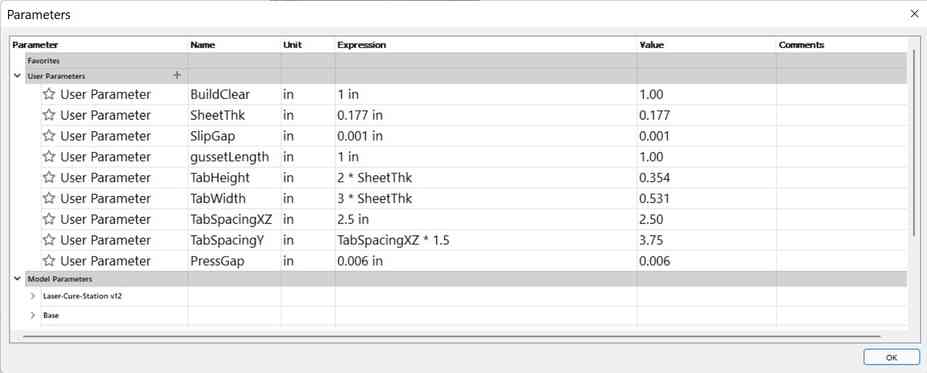
I started by creating my parameters and experimenting with driving them off of eachother.
I drew up the entire model and it was working perfectly aside from the tolerances. See below, where I was able to change the sheet thickness from 0.10” to 0.25” and have the model update without issue.

However, I wish I had looked more into tolerances before beginning to create another model. At this point, I realized all of my fits we’re loose slip fits because I designed slotss to be larger than the tabs by the amount “Gap”. Because of how a laser works, you lose an amount of the material on each cut called the “kerf”. So at this point, my gaps were 2*kerf + Gap. Therefore, I needed to subtract Gap to be a negative value so that we we’re counteracting the gap created by kerf rather than adding to it. I wish this had been as simple as changing a value to negative, but unfortunately these positive tolerances we’re built into the features I had built the model with, so this turned into an arduous proces. Along the way, I also realized it is important to only change the tolerance of one side of the equation, the slot or the tab. If you change both, you risk doubling up on your correction. In my case, I left the tabs at nominal size and changed the dimensions of the slots. This page does a great job of quantifying it. Takeaway, in my case the theoretical equation should be,
Tab = slot + 2*kerf - Gap
In order to quantify a slip fit vs. a press fit, I ran through a fit-test excercise. More details of this can be found on our group page here, since this excercise was also relevant to our group project. This allowed me to split Gap into two variables SlipGap = 0.001” and PressGap = 0.006”.
And of course, Fusion is not without its flaws too. I am learning the hard way that certain features are dependent on the visibility of objects (e.g align and cut). So if I rewind the timeline, with an object in a different hide/show state as when a feature was originally created, I may get different results. This makes for a very fragile assembly that needs to be hand repaired and diagnosed each time you use the timeline. I will avoid these features going forward for this reason.
Finally, it came time to run some test prints. To do this, I usually begin by temporarily slicing a model up via planes and printing only small sections. In this case, I decided the bottom left corner would be the best section to test the fits of the whole box, since these same joints are used all around the model. To generate these DXF’s, I attempted to use two different nesting softwares. More on that later.
You can see the results of two tests below (T1 and T2). The results of T1 first led me to think that the gussets we’re too loose and should be changed to a press fit. Additionally, the keys needed a tighter fit so they do not slip out and get lost. Lastly, it sparked the idea to add a ramp above the gussets. This ramp would both give the gussets more purpose and tie everything together more nicely.
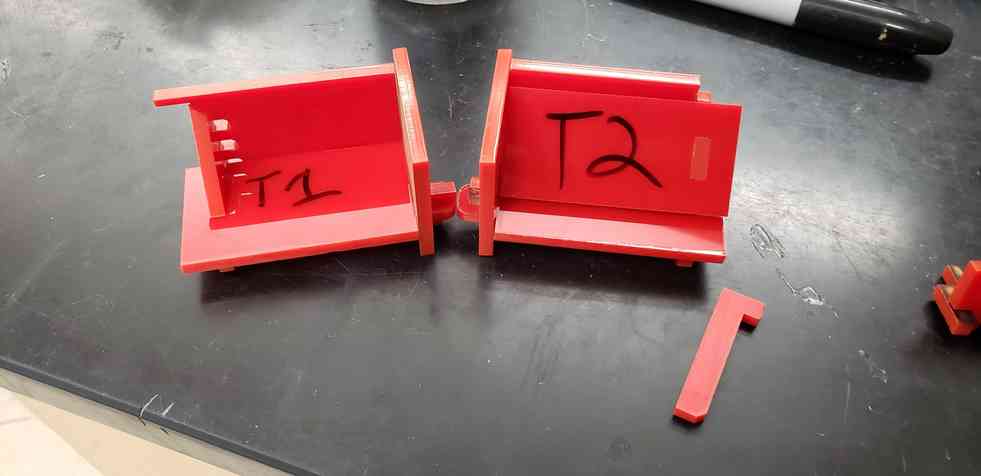
During T2, the press-fit piece covering the gusset snapped during assembly.
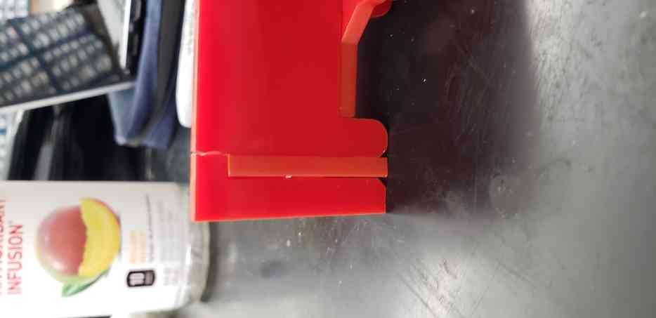
In the final assembly, the side wall would of course be much larger and may or may not snap again. Even still, assembly would be difficult and risky. More importantly, this failure highlighted and important error in my thinking. This gusset had 3 press-fit joints with other components, some of which have overlapping degrees of freedom. In otherwords, the piece is overconstrained. Therefore, I decided that no one element of the model should have more than 1 or 2 press fits, and their degrees of freedom should not conflict. Without going too deep, its useful to think about datums here. The design files for these Test prints can be found in my repo here.
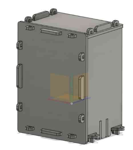
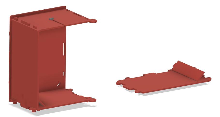
Then came the difficult task of designing a door that completely sealed off the interior (to prevent UV rays from escaping), while still avoiding the use of extra hardware. After giving it a lot of thought, I decided on pinning the door in the base and ceiling and using a tangency joint to control the motion. Awhile back, I watched Tim Hunkin’s Secret life of hinges. This proved very useful when designing the mechanism because I followed his methodology by first drawing the desired motion, start, and end-states in 2D, and then designing the hinge/structure second. This can be seen in my 2D sketch below whereby I drew the front door to cover the entire front, and began to draw surrounding structure and a track for the door to run in.
Note that this took some iteration, being sure to extrude the right sections for the different elements and not create interferences. As for a sliding tolerance, I added 2SlipGap as extra clearance (not interference), hoping 0.002” + 2kerf would be enough clearance to create nice motion. I made sure to leave the track piece as a body until I had a chance to mirror it to the base of the assembly. At that point the identical bodies were combined with the ceiling and the base respectively.
The tangency joint is a nice added feature that was missing from Fusion the last time I needed it. That said, it doesn’t work quite as well as you would hope. Even after grounding the base/ceiling, adding a planar constraint to the top of the door/ceiling, and adding a contact set to the door and ceiling, this motion was still chunky. Luckily, I know a workaround. You can precisely adjust the motion of an object using the move command, and Fusion should only allow that motion if the joints allow it. Therefore, I verified that the door could rotate 105 degrees as pictured above. A nice sanity check of this was attempting a combine->intersect feature between the door, base, and ceiling while the door was open. This feature failed, telling me that there was no intersection between them. The motion seems good!
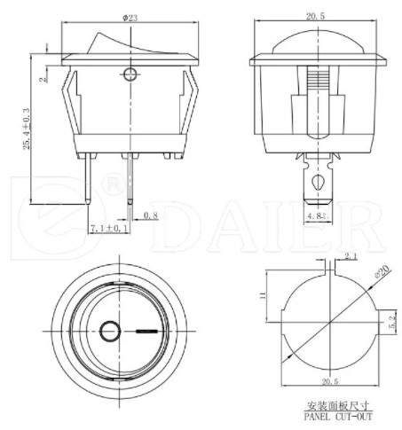
In order to help this box serve its purpose, I wanted to add an electrical power switch so I could easily turn on/off the UV lights within. In the electronics spread sheet, I found a KCD1 2 Pin 6A 250V Rocker Switch Round T85, which seemed suitable. Following that link, I found the datasheet and dimensions for the appropriate panel cutout. I added these to the model on the back-wall, along with some extra holes for cable management.
The last step was to give the door some interference elements when closed and a handle. I made the interference elements on the left side of the door and gave them 1 “SlipGap” of intereference, hoping that the slip in the tangency joint would allow the door to swing and close nicely.

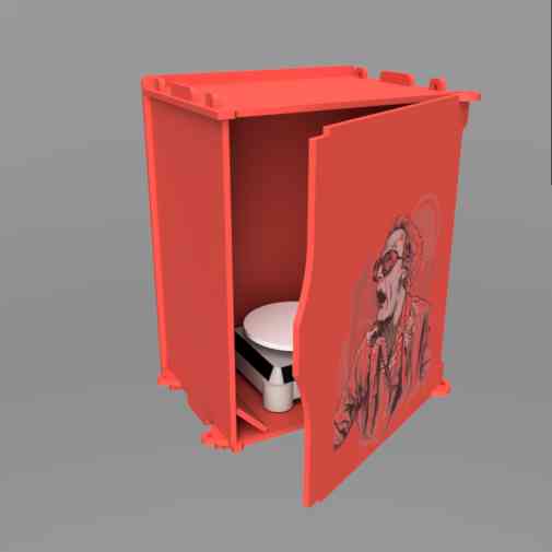
The real last step was to add some flair. Image credit to Behance user Earlson Vios. I made a quick render in the Fusion 360 render workspace by applying appropriate material appearances to the different objects, using the photobooth scene settings, slightly increasing exposure, setting the view to perspective, rotating the object to get good lighting inside the box, and running an In canvas render.
Nesting Software and Laser Cutting
Gotta love fusion and the integration. Speaking of which, I’m hoping to try out a nesting software to preserve as much of this high-quality acrylic as I can. A quick google search led me to the Fusion 360 plugin, Fuse2D. It was not very smart at detecting thickness and deciding which profile to face upward. Since this wasn’t doing exactly what I wanted, and I was eager to cut, I looked for another option. At this point, Fusion’s supported Nesting and Fabrication plugin was staring me in the face. I clicked a button to start fusions 7-day free trial.
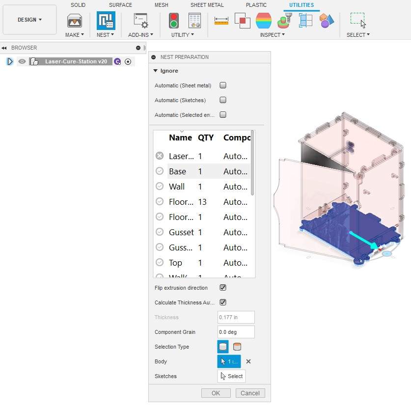
One trick to this add-in, seemed to be that Nest Preparation and Create Nest Study are found within different workspaces (Design->Utilities and Manufacturing->Fabrication repsectively). I did not need to change anything in the Nest preparation menu. It seems to be used to tell the software which elements are valid for fabrication, but it is seemingly very smart at auto-detecting these elements.
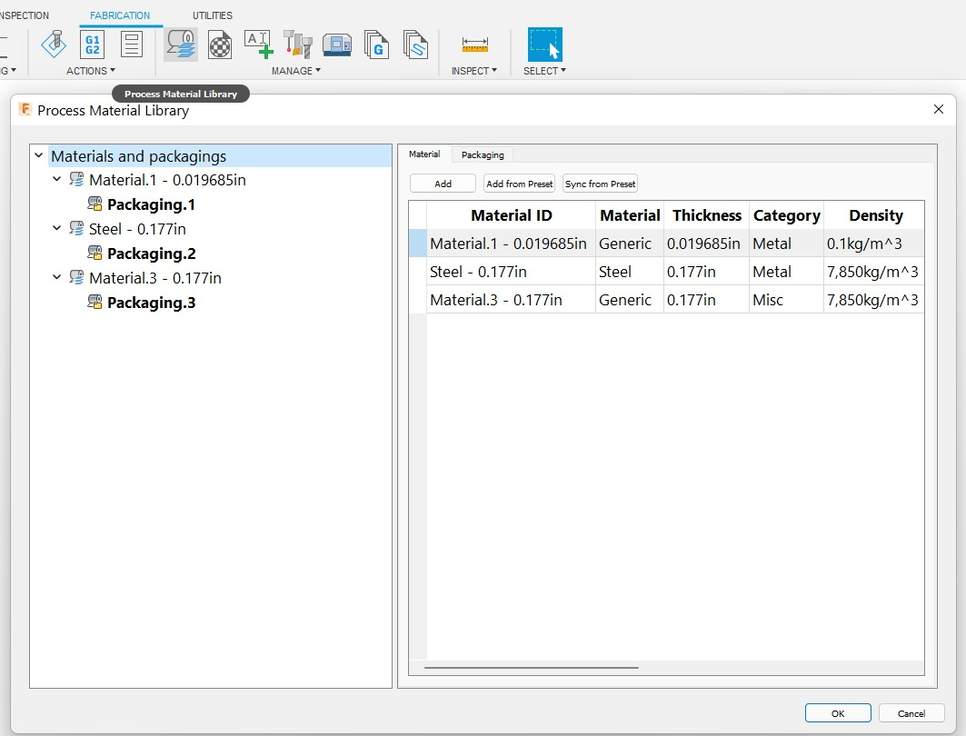
Then, within the Manufacture workspace, I navigated to create a Nest Study. Again, most of the settings we’re where I needed them, but it tooks some time for me to understand how to change some of them. For instance, I found it difficult to change the material stock under the Packaging tab. I eventually realized, these need to be changed prior to creating a nest study, under the Material Library function (see below).
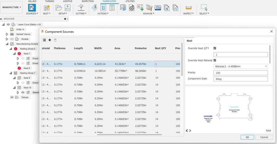
Finally, to get the number of each component that I wanted, I had to override some of the Nest Quantities listed under the Component Sources function.
Between these 3 menu’s, Nest preparation, Component Sources, and Create Nest Study, it seems this plugin offers too many places to pick which components are/aren’t processed. I count myself lucky to get it working. If I ever find myself doing lots of fabrication work, I will be hesitant to rely on this plugin. I will more than likely try to find something free, open-source, and more stable, that does not feel so convoluted. Eventually, I was able to generate these results:
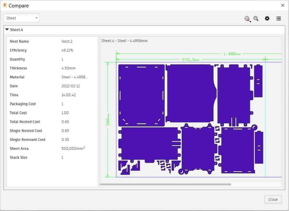
Not pictured, but I eventually had to go back and split the nest study into two different sheets. This was because I was unable to fit all of the pieces into one piece of stock and needed to separate them into two studies, and therefore two different jobs on the laser.
Once these studies we’re properly prepared, I ran into a critical error. By right clicking on a nest study and clicking DXF export, it caused a repeated crash in Fusion/nest plugin. Eventually, I found a workaround. Now checking Create mfg component file, which was previously unchecked. From there, I could create a sketch on the surface of one of the parts, project the geometry of all of the bodies, and export that sketch as a DXF. This error is a big reason I will search for a different nesting software in the future.
These DXF design files as well as .f3d design files are in a zip file that can be found on my repo here.
Laser Cutting and Assembly
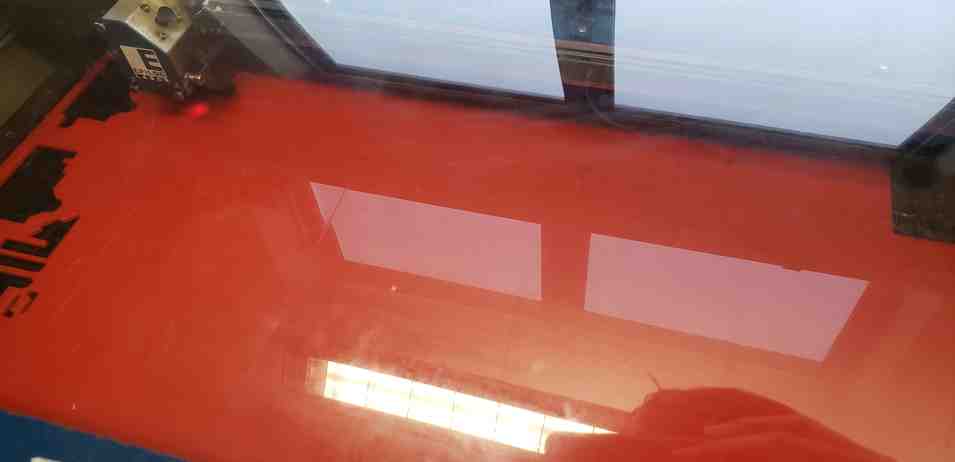
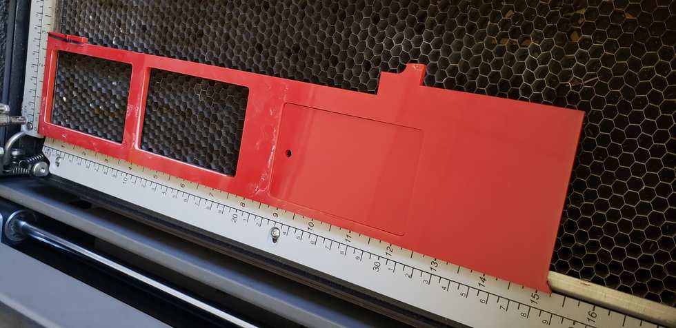
It was finally time to run the job on the M2 laser. I used the standard reccomended settings for cutting through and engraving 1/4” acrylic. Initially, I was getting some worrysome flames coming from the print. David Taylor reccomended I remove the protective covering from atleast one side of the acrylic pane, since this was giving it “a fuel source”. He reccomended removing it from the top-side, since the bottom-side could become scratched from the metal grating.
The only other issue I ran into with this print was that the door was cut with multiple passes. I later found out that I had the object duplicated within Corel draw. However, it was just the door that was double cut and I did not think it would be an issue becausse the stock was unmoved between cuts.
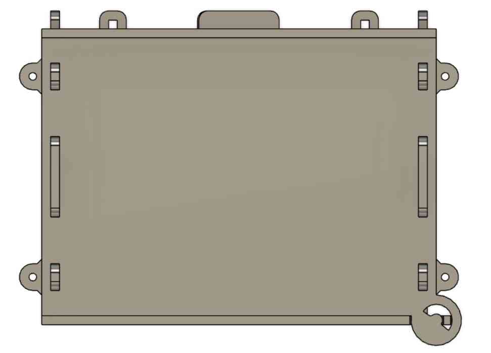
Then it was time for assembly.
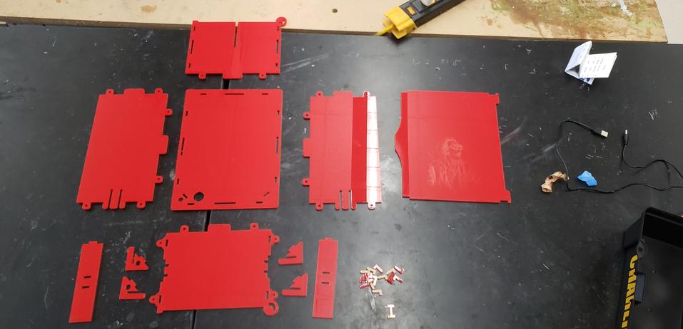
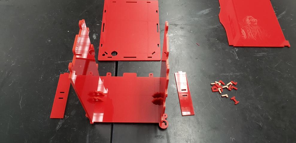
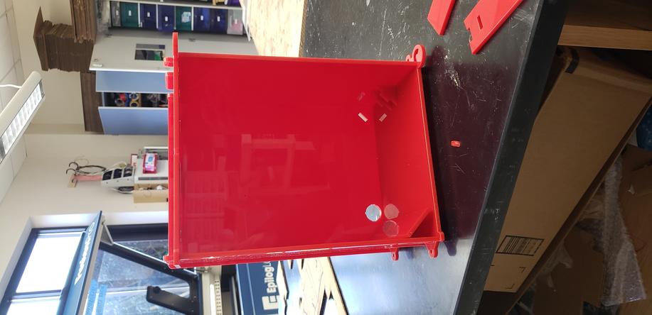
While first assembly went pretty well, the fit was definitely tighter than anticipated. I would attribute this to the stackup of tolerances. Each slipfit and pressfit tab theoretically fit nice and loose or snug respectively. However, since each panel uses mutliple tabs, they seem to be fighting eachother and overconstraining the panels. It makes sense that this issue was not caught during my test prints, since there we’re far less tabs involved and usually only one tab per panel. The result was a hairline crack in the back-panel and one of the side-angle pieces breaking entirely.
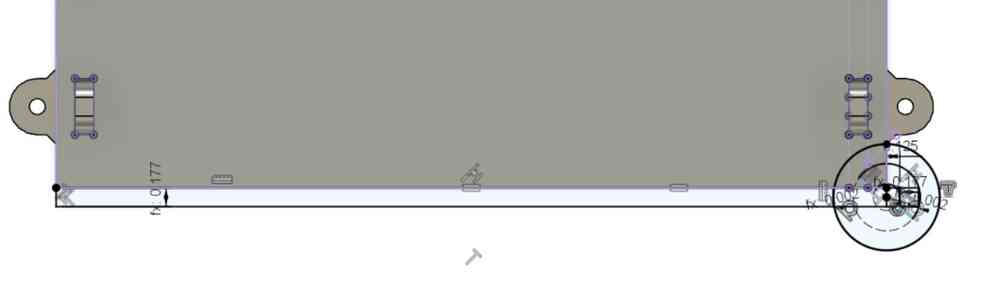
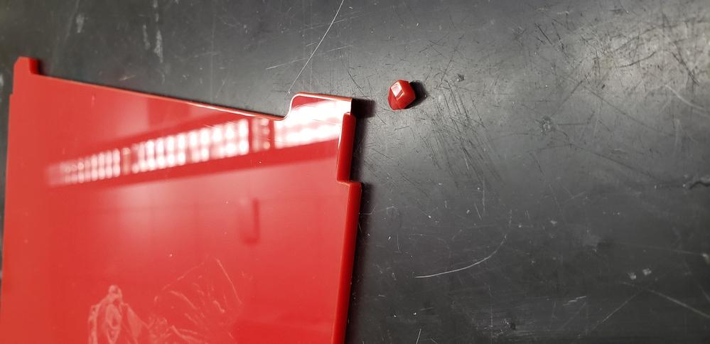
This issue will be easily resolved by reducing the variable SlipGap and changing some of the press-fit joints to be slip-fit. The second issue was more indicative of a bad design. See below, where the hinge pin of the door sheared off.
A quick root-cause analysis:
- A square peg was asked to move smoothely against a ring track.
- A corner of the square tended to get stuck on the arced shape, despite the extra clearance added between the two.
- The stuck corner added a torsional force to the square peg which caused the peg to shear under torsion.
- The peg sheared because it was small (0.177”x0.177”)
- The design required that this piece be square, which limited the dimensions to the sheet thickness squared. Additionally, becauase of the limitations of a laser-cutter, this piece could not be made round, which would be most appropriate.
- A square on arc tangent joint is not suitable for a brittle material such as 0.177” thick acrylic. Redesign of this joint will be needed.
Note: Both of these broken pieces are issues with elements added near the final stages of the design and were largely untested. I am beginning to see the value in testing designs with cardboard, especially when working with expensive materials such as acrylic.
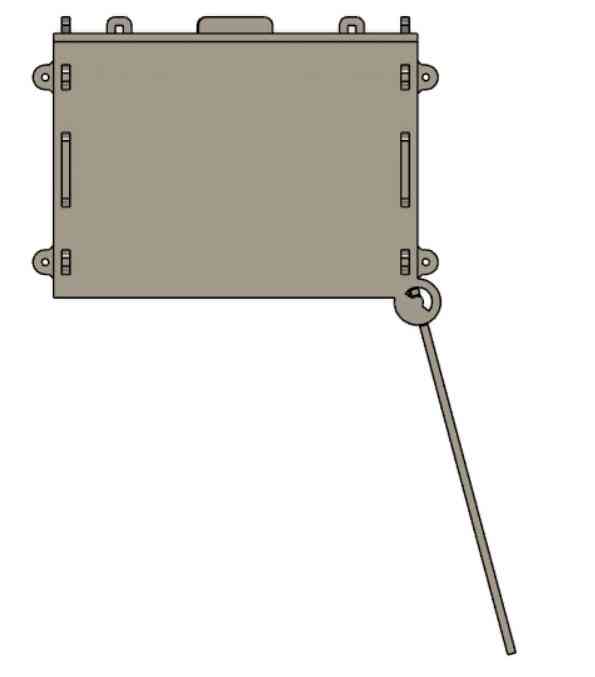
Luckily, the door was designed to press fit into the main box, and this portion of the design worked. So even if the door-hinge did not work, the door was still able to reliably close the box. As such, I cut off the remainder of the broken hinge pins using the laser and will settle for a door that simply separates from the box for now.
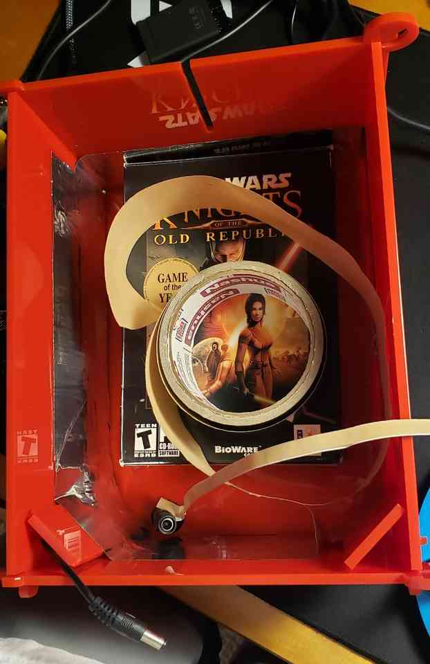
Cure Station Final Touches
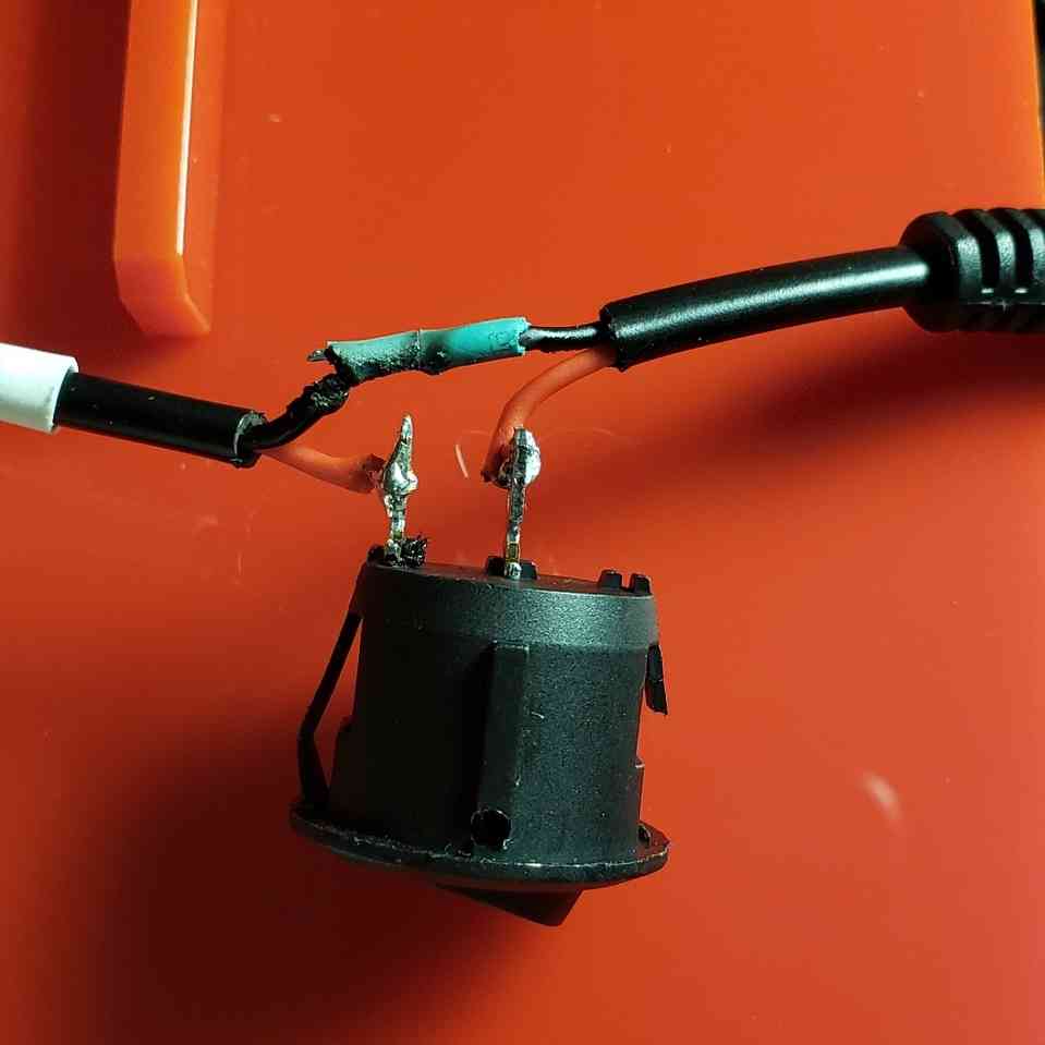
Now that the assembly was done, it was time to make it a cure-station by adding shiny material on the inside of the box as well as wire in strips of UV LEDs. First I cut into the hot-wire of the LED strip and soldered the 110V switch in series. Unfortunately, we did not have the proper connector types so I had to settle for the ol’ twist and solder method. This is what happens when a mechanical engineer trys to electrical engineer:
Last note about the switch, you will see that one side of it broke off when attempting to push it into the back-panel of the box. It seems the switch is intended for thinner pannels than 0.177”. The datasheet did not verify this point. Luckily, the switch still fit into the panel snugly with one side broken.
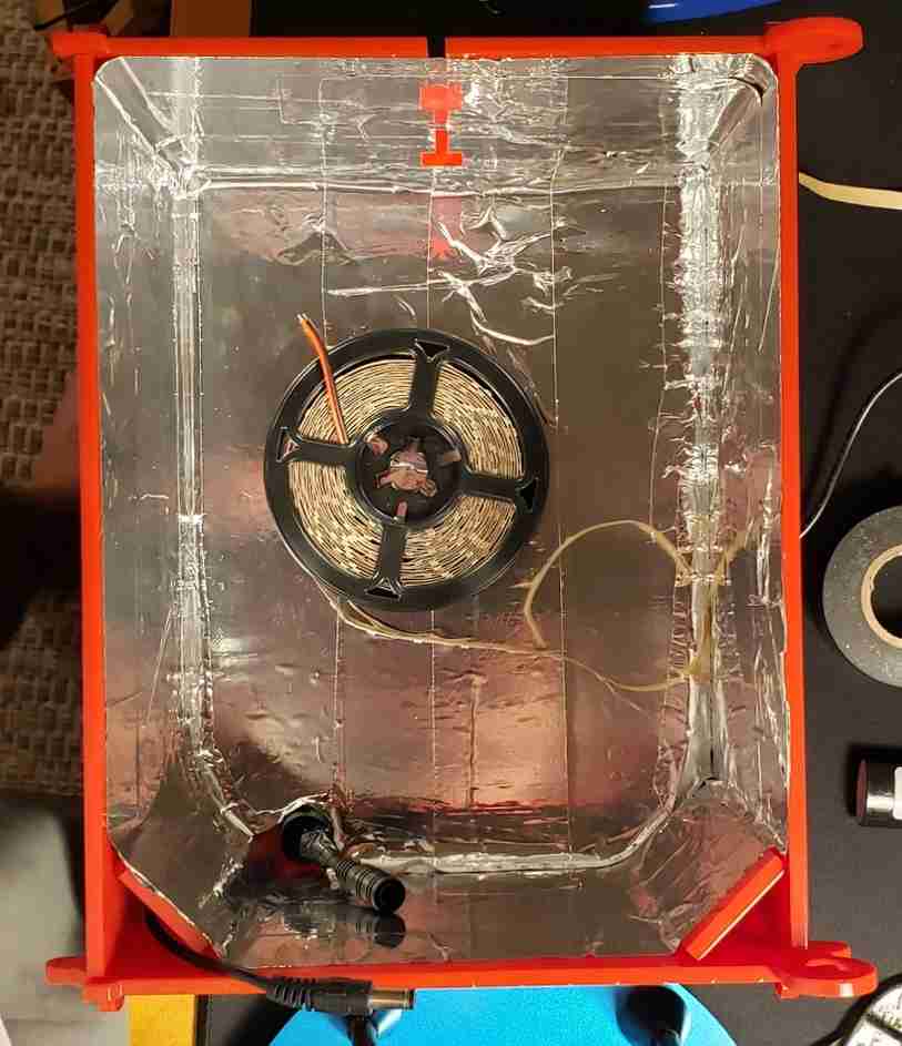
For shiny material, I used HVAC aluminum tape.
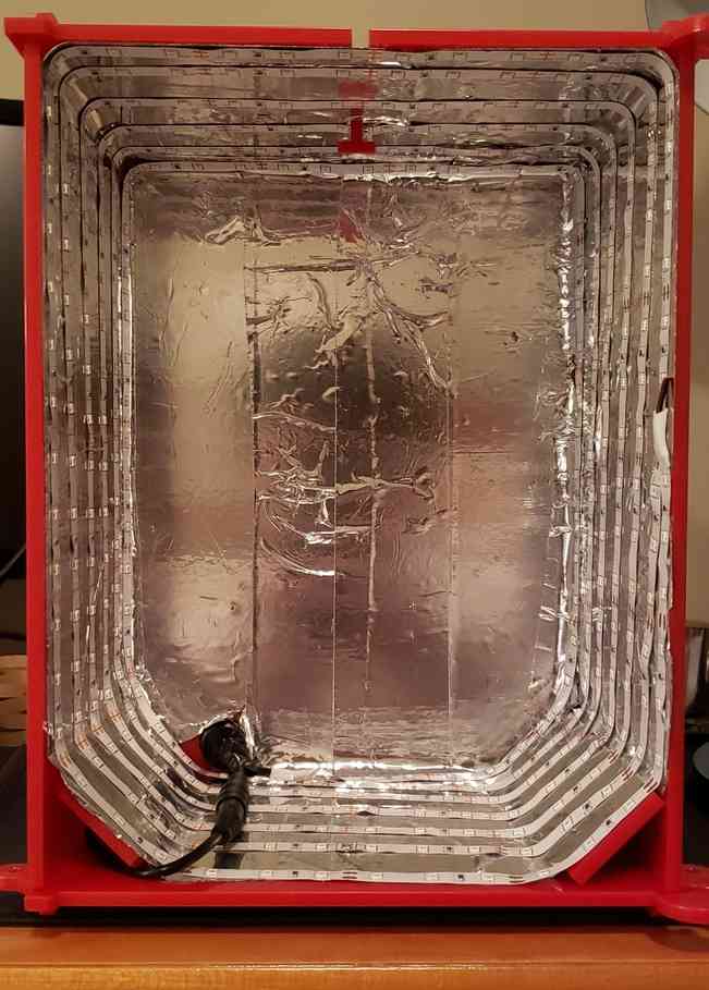
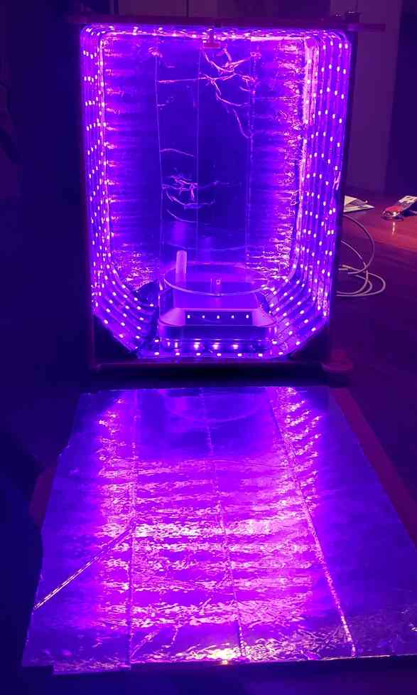
And then the LEDs strips were added. I chose a spiral path that would allow me to avoid making any out of plane turns, and having to do more soldering.
Then I added the solar powered turntable which will ensure the prints are properly rotated and voila! Happy to call it done. Now I can get to some resin printing, documented here.
Fulfilling the assignment
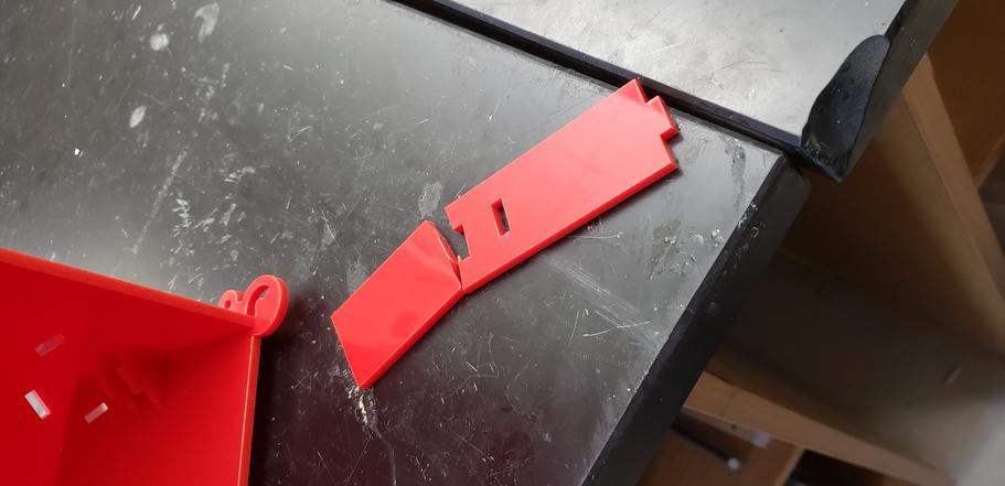
Note, when it was all said and done, our global grader pointed out that to fulfill the assignment, this “a parametric press-fit construction kit, which can be assembled in multiple ways.” I had focused on making it parametric, kerf, and creating good joints without the need for screws/glue. I must admit, this was a purpose built device that was intended to be assembled as pictured above. That being said, because the joint tolerances are universal and I accounted for kerf, the kit can be assembled in other ways. For instance, by removing the side wall, flipping the gussets 90 degrees, and adding the angled piece, you can build a ramp. This could be useful as a jig to lay up a composite or set something up to glue at a 45 degree angle.
Again, since the joints are universal, the kit could be disassembled and reassembled in other, somewhat nonsensical ways. That said, I wouldn’t recommend it. This kit is currently serving its most useful purpose, as a cure station for resin prints, and serving it well.
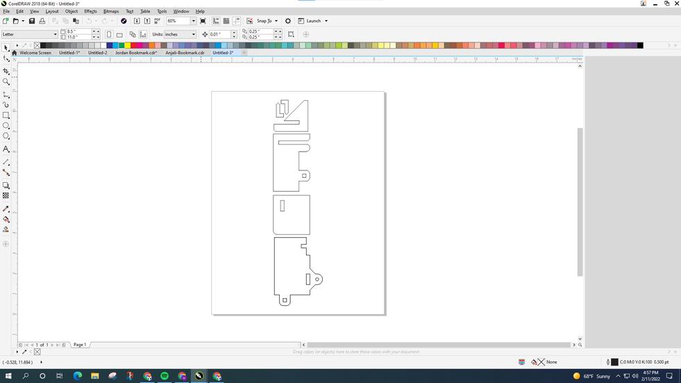
Production of Queen of Hearts, Corel Object Manager, Troubleshooting
One other laser project was undertaken. This project was not for an assignment, so I will make this entry brief and focus only on the learning that took place. Even still, design files are in a zip file can be found in my repo here.
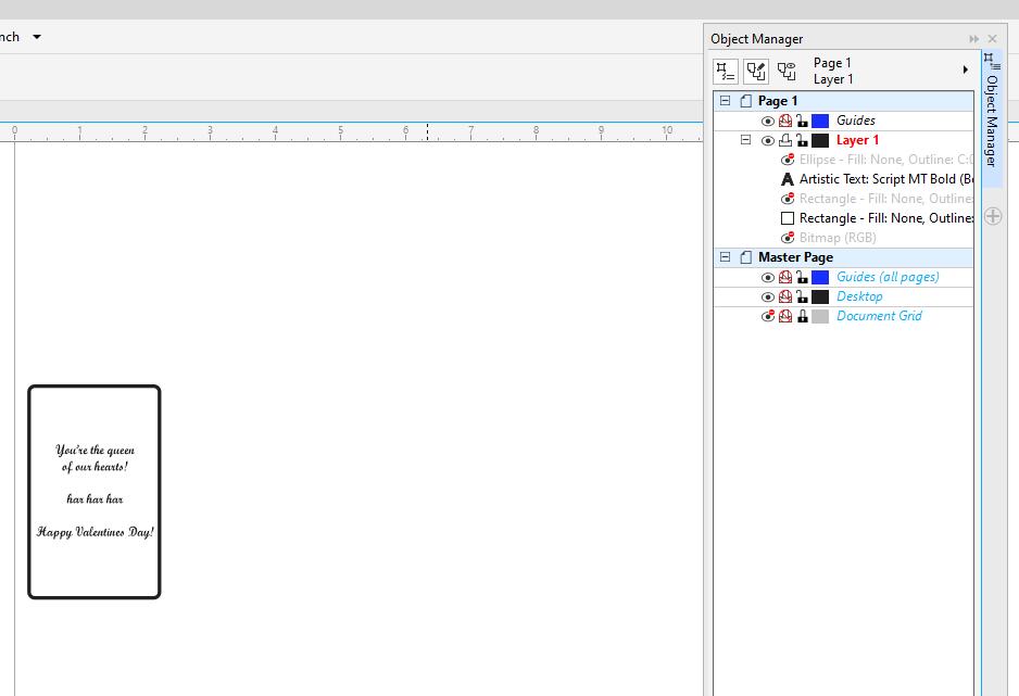
The hope was to create a 2-sided Valentines “Card” by simply flipping the card in place and printing a different design on the other side. However, the two sides shared similar elements such as the engraved border ring. To this end, I discovered Corel’s Object Manager, which proved very useful for showing/hiding objects. This allowed me to overlay all of the elements from both sides of the card in one place, and simply toggle the right ones for the front and back of the card.
Then it came time to print the queen, flip it in place, and print the 2nd side.
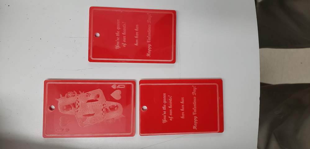
As you can see, I was running into an error whereby the second side of the card was offset and not centered. The first time this happened, I assumed I had bumped the stock while flipping the card over and so I simply tried it over again, being extra careful this time to flip it in place without an offset. When the issue occurred a 2nd time, I knew something was up on the software side.
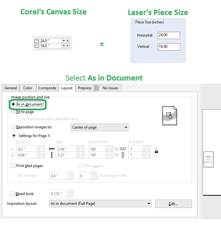
After some poking around in the Corel print settings menu, I realized that the image was showing up in a different place on the print-preview than on the Corel canvas. Then I remembered David Taylor mentioning that the Corel Canvas size must match the Laser’s Piece Size. I like to set these to the size of the print bed, but you could also set them to the size of the stock. The important thing is that these values match. Also, by checking As in document, under the Layout tab of the print settings, we can assure that the print-preview will match the Corel canvas. So now our canvas matches our print preview, which matches the information we are sending the laser cutter.
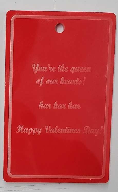
Success!! Valentines Card/ornament done.
Last note about this project. Upon closer inspection, the raster image left a slight matte sheen around the queen’s background (as seen above). This is more than likely because I forgot to remove the bitmap’s white background while importing into Corel. In the future this can be mitigated by removing the backgrounds of images.
- Don’t weed off of the original decal backing, transfer to different substrate first
- Design with simple shapes without too much detail.
- Workflow refinement: Concepts ->
Corel-> Paint (if need-be) -> Corel -> Silhouette - Registration marks should be made in Silhouette, not Corel.
- Less transfer tape, more sharing of substrates
- It takes awhile to make stickers.
- Waste is a part of making things, but better to waste more now than more later.
- Don’t fight your tools when you prefer a different tool. Give it reasonable effort then move on.
- Tab = slot + 2*kerf - Desired Gap
- Some Fusion functions offer different results based on the show/hide state of objects. Avoid these functions.
- Test designs in cardboard!!
- Avoid overconstraining and object with multiple tight tolerances in multiple dimensions.
- While each individual joint might theoretically work. Mutliple joints across a face will fight eachother due to stackup tolerances.
- Why so many joints bro?
- Play to the strengths of your material/tools. The first door idea neglected the geometric constraints and the brittle nature of acrylic.
- Remove top-layer of protective covering from acrylic or you risk fire.
- Neither Fusion nesting plugin offered satisfactory results. Search for new tool next time.
- Engrave acrylic on the less powerful machines. Counterintuitive.
- Make sure Corel canvas dimensions match “Laser Piece Size” in preferences.
Note: All design files and images can be accessed in my git repository found here.
All works shared on this site 'A Fab Academy Journey with Charlie Horvath' by Charles W. Horvath are licensed under Attribution-NonCommercial-ShareAlike 4.0 International![]()
![]()
![]()
![]()