Week 8 Students B
This week our group was tasked with completing our lab’s safety training and testing runout, alignment, fixturing, speeds, feeds, materials, and toolpaths for our machine. Project members: Dariyah Strachan, Dylan Ferro, Ginny Foster, Stuart Christhilf, and David Tian
CNC Safety
All students must review the workflow for the machine they plan to use and check with a teacher before using that equipment. Also whoever is in the room while the CNC machine is running must wear eye and ear protection. There must be two people in the room at all times if the machine is running. Finally, an adult must be aware that the equipment is in use and approve the usage of the machine.
Runout: Stuart Christhilf
For the Run-Out test we tested how far the spindle/ bit rotates from its true axis by using a gauge on the bit to test it. We started by putting together the gauge
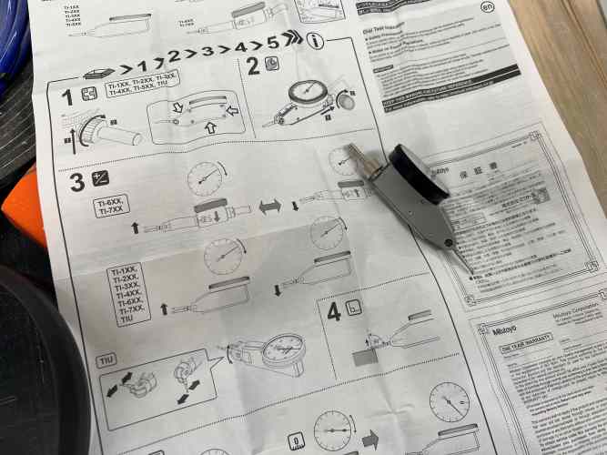
after we put it together we then had to put it to the top of the bit to see how much off the axis the bit was by seeing how much pressure was put on the gauge.
In both test you can see how the dial only is moving a very small amount showing how the bit is “running true” or within a .005 of the true axis that it is on.
Alignment: Ginny Foster
For alignment we just moved the spindle of the machine around using the shotbot commands from inside the shopbot terminal. To move the x axis and y axis, we typed
J2 5,5
If we needed to change a bit or install materials, to raise the spindle all we had to type in was
JZ 6
All of these numbers represent inches on the bed of the machine so if J2 5,5 was typed in the spindle would move to an X position of 5 inches and a Y position of 5 inches, and the same goes for the spindle.
Fixturing: Dariyah Strachan
Our lab offers several options to fasten materials to the bed of the CNC machine, they are as follows:
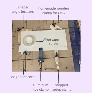
Our lab no longer allows the us of screws to fasten down materials due to the possibility of the bit hitting the screw and breaking into shards of metal. This is particularly dangerous because the metal shards will be sent flying across the room upon impact which can seriously injure people located nearby.
Additionally, Shop Bot has some official documentation on their recommended way to fixture a project depending on your needs. They recommend the follwing: - Screws for spoil board or a material if you do not care about its appearance - T tracks and rails for movable and customizable fixturing solutions - Clamps provide strong holding power and are ideal if there is no excess material in which to drive screws into - Press fit jigs give great holding power and can be made using the CNC; Jigs are good for thick materials, materials which you cannot drive screws into because of space or finality, and small workpieces - Adhesives for thin materials - Vacuum hold down systems for repetitive cutting of plywood or large materials (Note: this is a special add-on feature and must be on your specific CNC machine, our lab does not have this capability) - Use of tabs in your CAM design to prevent shifting of a cut out piece
Speeds and Feeds: David Tian
Feed rate:
This unit is measured in inches per revolution, and measures the distance in which the bit travels every time it spins. This is important because it tells you how fast the bit is moving through the material, which if it moves too fast, might not produce a smooth cut.
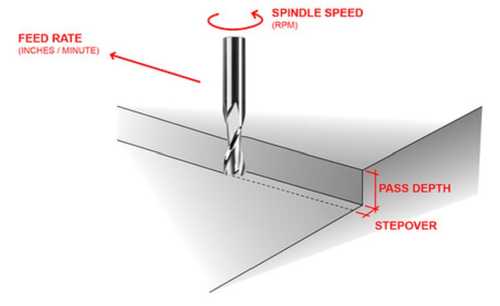
Speeds: This is the rate in which the bit spins, and it is measured in rpm, or revolutions per minute. It is directly related to the feed rate, as it is inversely proportional to the feed rate. If we keep the feed rate the same, then the bit would travel less per revolution if we spin the bit faster. The opposite is true if the feed rate is decreased.
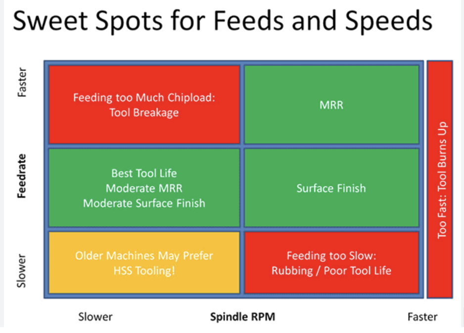
This chart also shows the relationship between Spindle RPM and the Feed rate.
Materials: Ginny Foster
For the Shopbot Desktop MAX, According the the Shopbot Handbook the Shop Bot is capable of machining the following types of materials: - Wood, plywood or hardwood - Plastics - Aluminum and other non-ferrous metals - Foam sheets for sign making or insulation
Toolpaths: Dylan Ferro, Dariyah Strachan
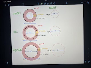
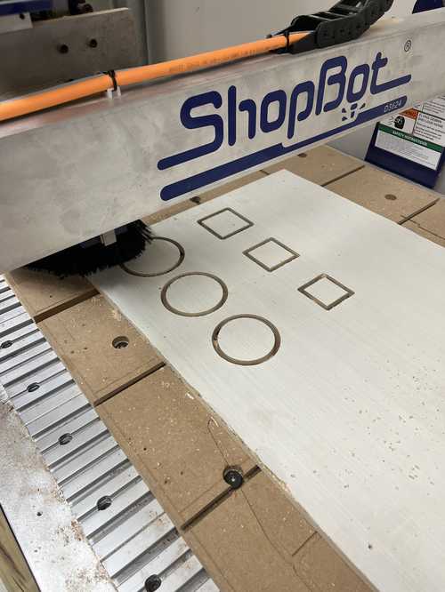
To test the tool paths we designed 3 identical squares measuring 2in x 2in and 3 identical circles 3in. For both the square and circles, one of each had a toolpath set to inside, on line, and outside. We then milled them out on the small CNC machine and measured the difference in measurements.
Milling on the Small CNC: Dylan Ferro
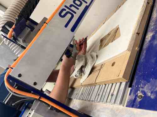
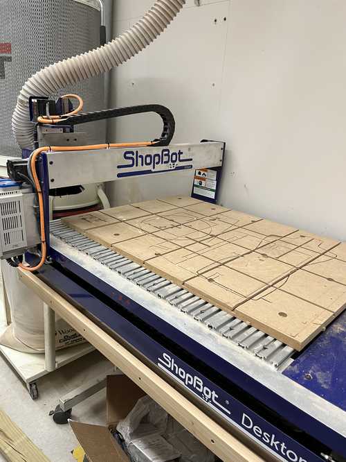
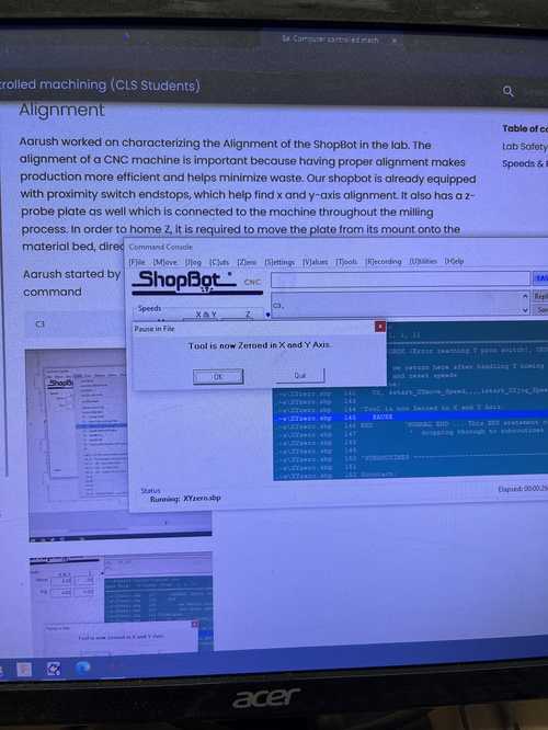
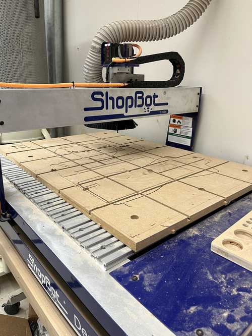
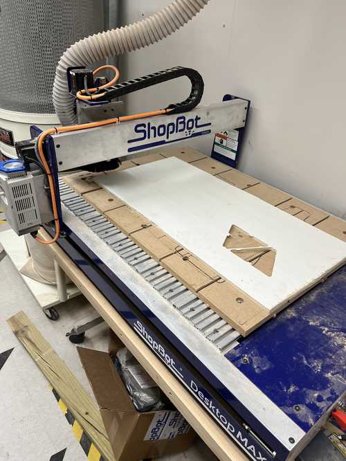
In our lab we have two ShopBot milling machines, a ShopBot PRSalpha, and a ShopBot Desktop MAX. This we our group used our labs Desktop MAX, that will be referred to as the “small” CNC in comparison to the “large” CNC that is the Shopbot alpha. To start the milling process the first thing you must do is prepare the files to be milled. We did this by designing the files in aspire, and setting the feeds and speeds to accommodate the wood we were using, birch plywood. These amounts were 18000 rpm for the spindle speed, 250 in/min for the feed rate, and 20 in/min for the plunge rate. We also set the material thickness to .466 in because our sheet of half in plywood was not exactly .5 inches. Next we created the toolpaths and made them one file to download. Next we prepared the machine to be milled on. The first step in using any larger sized CNC machines is to prepare safety gear, we got safety goggles and ear protection for the sound the machine makes while cutting. After we had our safety gear, we turned on the machine by first switching on the power. Then we checked the bit to ensure it was inserted properly, that it was the right bit to use, and then inserted and turned the key to enable spindle rotation. Then we started the spindle warmup by following the instructions found here. The only modification we made to these instuctions was after about 7 minutes we turned the machine to 150hz becuase for our cut it would be spinning at 300hz (18000 rpm) because the instruction say to warm up the machine at half the intended cut speed. Next I zeroed the x and y axes with the command C3. This zeros the x and y axes with the proximity buttons on either end of the machine. Here is the machine and the message that comes up when that is done correctly.
Now we jogged the machine by 15 on the x and y axis by using the command J2, 15, 15 and this is what the machine should do:
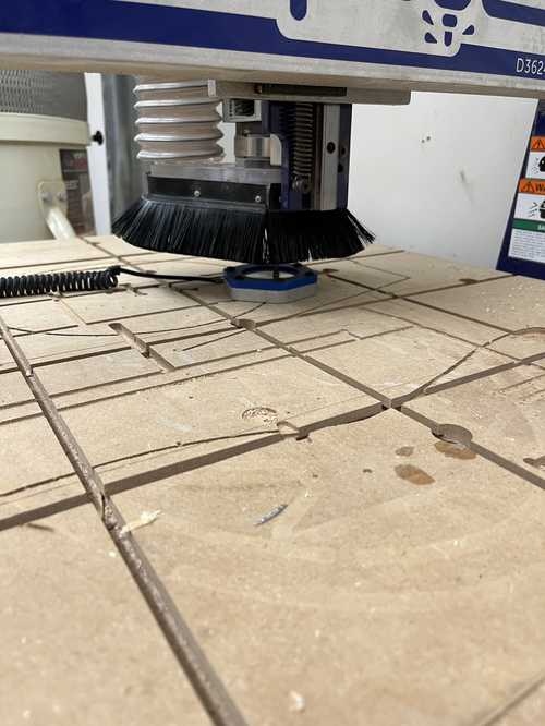
Next we zeroed the z axis by using the Zero plate. It looks like a blue hexagon with a mirror like surface in the middle. Place the plate under the spindle and then enter the command C2 to zero the z axis and watch carefully to make sure the spindle gently touches the plate. Like this:
After that is done remove the plate from the table and place it somewhere where it will not go flying when the machine starts moving. Next for safety I used the command JZ, 3 to raise the z axis to 3 inches from the table.
Next I secured the wood to the table using a brad nail gun to make sure the wood stays in place and no metal shrapnel will be thrown around the room if the machine hits a nail. Since the board is not place din the middle of the wood I jogged the x and y axis to about the bottom left corner of the wood with the command J2, 3, 3 and this is what it looked like:
After that I started an air cut. I did this by opening our file and pressing cut with 3D offset. This would offset the cut 1 inch in every dimension. After this cut looked like it had no errors I started the real cut by doing the same process but selecting no offset instead of 3D offset. The cut worked perfect and here were the results:
To remove the circles from the tabs I used a hammer and chisel and broke away the tabs.
Measuring the Toolpath Differences and Analysis: Dariyah
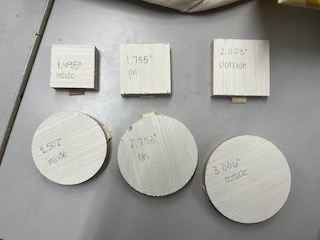
There was an obvious size difference between the inside, on line, and outside toolpath how ever I measured them to get exact dimensions. The square that was milled with an inside tool path measured 1.495in and the circle measured 2.502in. For the square and circle milled with a on line toolpath measured to be 1.755in and 2.753in. The square and circle that were milled with an outside toolpath were the largest measuring to be 2.005in and 3.006in. This is because of the size of the bit. When a cut is made inside of the line, it will take away extra material due to the size of the bit. The on line cuts were the smaller than they were designed to be because the bit was cutting one the line they were set to, so half of the bit size would be removed from the cut. The outside cuts were the closest to the size they were designed to be because the edges of the bit were cutting along they were designed on, so the bit’s size did not effect the cut.
Better explained in this diagram: