Week 9 Students B
This week our group was tasked with characterizing out labs Bantam milling machine. Project members: Dariyah Strachan, Dylan Ferro, Ginny Foster, Stuart Christhilf, and David Tian
Updated Othermill CNC Workflow: David Tian
Bantam recently released a new version of their software that is much easier to use and operate.
- Download file
- Geber
- Eagle.brd
- SVG
- KiCad Files (ONLY download the front copper and edge cuts files)
- Clean the Bed
- Use a vacuum and remove loose materials.
- Wipe down with alcohol
- Material
- Select material - generic or FR1 NOT FR4
- Measure the width and height of the conductive material you wish to mill (PCB - FR1)
- Enter the width and height values.
- Tape down the material
- Use Nitto tape (double-sided tape)
- No overlaps
- No wrinkles
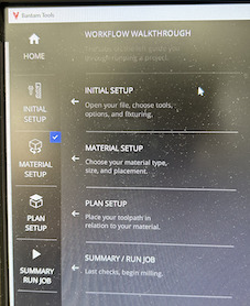
- Open Bantam Software
The setup portion is inside the bantam file, and it tells you step to step what to do:
-
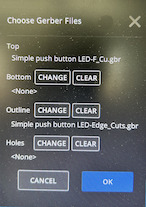
Load File
-
Open the file in the file setup tab
-
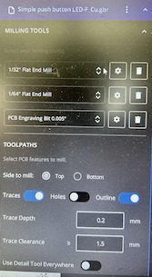
Trace Depth: 0.20 mm
- Trace Clearance: 1.50mm (Note: you need to change this from the default setting of 0.15)
- Bits:
- 1/32” Flat Endmill
- 1/64” Flat Endmill - select this setting as opposed to 15 degree Taper Stud0.015” 15 degree
- PCB Engraving Bit 0.005”
- Probe Material Thickness
- You can just use the install tool tab and follow the instructions there to conduct the operation in which the bit touches the metal part (NOT the stock)
- Click on “Probe Material” to find the material thickness.
- Note that you must flip the electron-conducting switch in the CNC in order for this step to work!
- When milling multiple boards, use the minimum material thickness of all the points probed. Values can vary from 1.67-1.95mm, which matches the manufacturing tolerance of the board at +/- 0.15mm.
- Make sure to leave an offset of 0.01 mm for the nitto tape:
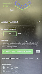
- You can just use the install tool tab and follow the instructions there to conduct the operation in which the bit touches the metal part (NOT the stock)
- Home Machine
- Prep Machine & Configure the job in Bantam Softwarethe Bantam Tool
- Select tool (end mill or engraving bit) by selecting change
- Choose tool under New Tool
- Install the tool by loosening collet and replacing tool
- Click continue
- Verify tool position
- Locate tool
- Milling the face of the board
- Setup the board in the Bantam Software and be sure “Trace and Holes” are selected. Be sure “Outline” is NOT selected
- Select the ‘PCB Engraving 0.005”’ tool
- Select the ‘1/64” Flat End Mill’
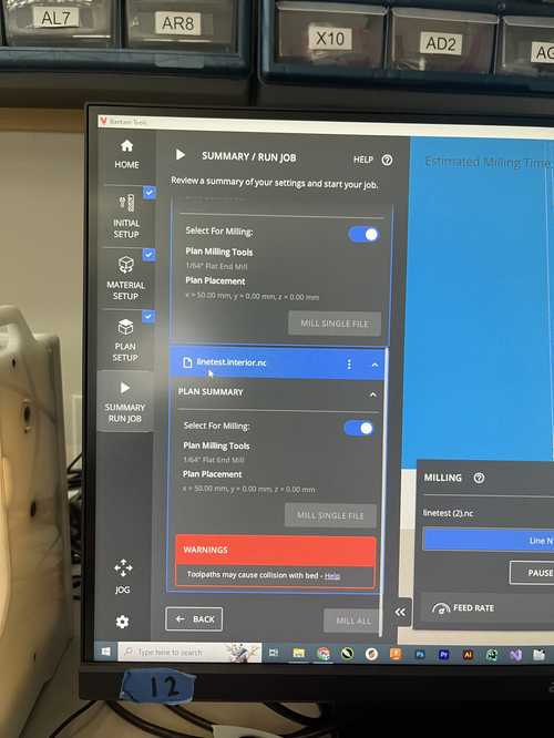
- Confirm there are no red areas on the face of the board in the Bantam Software.
- Verify only the parts to be milled are visible in the software
- Start milling using the “Mill All Visible” button.
- Follow-on screen instructions for inserting the correct bits
- To maximize bit life, be sure to place the white foam on board when changing or installing bits
- Be sure to periodically check the bits under the microscope before installing to confirm they are still sharp.
- Cutting Out the Board after milling the face
- Deselect Traces and Holes in the Bantam Software
- Select Outline
- Add ‘1/32” Flat End Mill’ to the Milling Tools
- Confirm that only the board outline is visible
- Start milling using the “Mill All Visible” button.
- Follow-on screen instructions for inserting the correct bits
- To maximize bit life, be sure to place the white foam on board when changing or installing bits
- Be sure to periodically check the bits under the microscope before installing to confirm they are still sharp.
- Board Removal
- Move the PCB board to the loading position and vacuum the board.
- Use the 5 in 1 paint scraper to remove the board from the machine.
- Vacuum inside the machine to get residual debris after the board is removed.
- Put all bits back in their original containers.
- Clean Up!
- Vacuum inside the machine to get residual debris after the board is removed.
- Put all bits back in their original containers.
-
Note that not every measurement setup could apply to your CNC machine, so it is important to adapt the above workflow to your machine.
Cutting Test Strip with 1/64 inch flat endmill: Dylan
First I chose the file for the design. Then I chose my tools, For this cut I used a 1/64 flat endmill.
Next I inserted the copper sheet into the bed my placing 3 strips of nitto tape and sticking it to the bed making sure to line up the bottom left edge. After attaching the copper sheet to the bed I added a .01 mm offset because of the thickness of the tape that would offset the copper from the plate of the machine. Then I attached the clip to the copper sheet to make it conductive for the z plate probing. I then probed the height and got a 1.8 mm sheet thickness which sounded right. Then I double checked that the design had no offset since I was milling on the bottom left corner and sent the design to the machine to be cut. After the cut was done, I vacuumed the extra shavings away from the board and then pulled it off the plate.
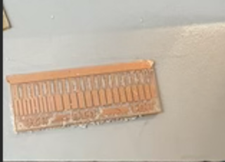
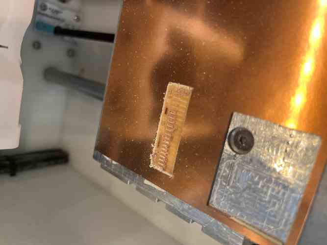
Cutting Test Strip with 1/32 inch flat end mill: Stuart
for this test I followed the same exact steps as Dylan above, but I just replaced the 1/64” bit with a 1/32” bit. You can see in this picture below that the result was a lot rougher and less defined than the one with the 1/64” bit, but that is to be expected.
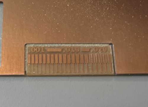
Cutting Test Strip with .005” V engraving bit: Ginny and Dariyah
To do this test strip we followed the same method that Dylan used above but instead of a 1/64 I used the two large and small wrenches to swap out the bit with a .005” engraving bit. Dariyah began by loosing and letting the 1/64th bit drop onto the piece of foam placed below it to ensure the safety of the bit. Then Ginny had Dariyah put in the engraving bit and hold it into place while she tightened back up the spindle. From there we just went through the setup wizard for installing a new bit and we were good to go. Because we were using an engraving bit, we needed to swap out the bit mid cut so that the machine could do the edge cuts with a bit that was meant for doing this as an engraving bit is for as the name implies: engraving. So about 4/5th into the cut, the wizard prompted us to change the bit to a 1/32 flat endmill. We followed the same steps as above and once installed we resumed the cut. Once finished we used the vacuum to remove the copper shavings and then Dariyah pried off the completed board and extra stock. We noticed that the finish of the strip was very nice and clean and similar in quality to the 1/64” endmill test strip. This told us that if you need a good quality board you should be using a 1/64” endmill or a .005” engraving bit for the best results. It also showed us how to swap out a bit mid print.