10 & 11. Machine Weeks - Self Documentation
The Fab PCB BufferOver the past few days, I've been working on our machine weeks project (see here), which is a 2-axis post pcb-mill buffering machine. Its intended purpose is to clean any loose burs leftover from using an endmill to route your pcb. See example image to the right. My goal was to design circuits and code to control our stepper motors using the Urumbot open-source design by taking the original SAMD and milled USB 3.0 plug-in using functional C, and replacing those components with a Xiao Seeed RP2040 built-in usb-c and object-oriented MicroPython. This is in hopes to make the design more user-friendly, and easy to replicate with minimal tools, as well as taking advantage of the higher processing power cpu to take a more easily-expandable object-oriented approach. |
|||||
|
|||||
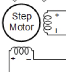
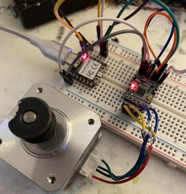
Testing the Motor DriverNow, keep in mind, I am not 100% sure on the current drawing capabilities of the 5v VBUS pin, connected directly to the usb power, so we will be trying to keep the current draw here lower than an amp to be safe. Perhaps some future stress testing on this will be needed later... but in the interest of time, we will proceed and throw in a large capacitor.I decided to use the DRV8833 motor driver, since it was one we had on hand at the lab, and an abundance of. I assume that with my prior knowledge built from the electronics weeks, I could build a board similar the the Urumbot. By using the immediately available parts, I can start prototyping sooner, and always use the original design components as a backup instead of just a reference. I quickly tested using a breadboard, a seeed xiao rp2040, a drv8833 motor driver, a stepper motor, and Thonny as an IDE and programmer for micropython. This step is important since it will validate the core functionality of my design using the xiao in conjunction with the drv8833 and leftover NEMA motors from an Ender 3. One issue I encountered was the not-so straightforward connections of a 6-pin NEMA motor. This motor basically consists of 2 coils at a 90 degree vertex, where changing the polarities causes the magnetized core to move. There are 2 pins that connect to either end of the coil. Each coil also includes a center-tap, which effectively is able to divide a coil in half, allowing for more precise movement. As each step consists of 1.8 degrees for our motor, I chose to ignore the center cap for our use case, as it would just add code complexity. |
|
||||
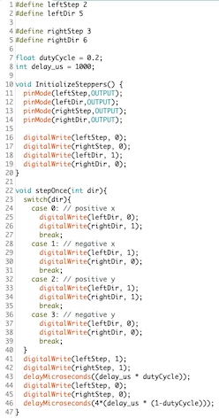
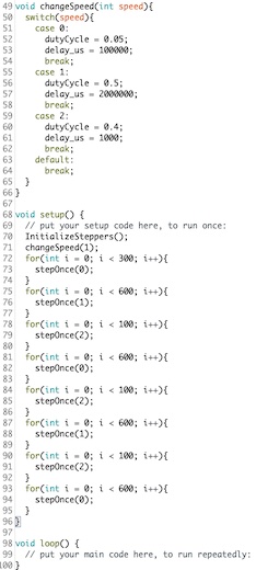
| I still included potential to control the center taps in my circuit design though. To figure out which pin on the motor corresponded to which coil I found a nifty trick - using a multimeter, you can use continuity tests to find both ends of the coil. Switching the code to manipulate the polarities of these pins caused my test code to work! This code was very simple, and just consisted of turning pins high and low to change the polarity of the motor via the motor driver. Make sure to NOT DRIVE THE MOTOR THROUGH THE MICROCONTROLLER. It is not meant for high current drains like that. Technically, it's risky to even draw power through the VBUS pin of the XIAO, as I am unaware of the current drawing limits on the via itself. But, since it's not running directly through the RP2040, I think the controller is at little risk, and a simple diode replacement would fix it. A breakdown of the coding implementation to control the motors via micropython is explained further down the page. | |||||
Designing the Motor Controller PCBs |
|||||
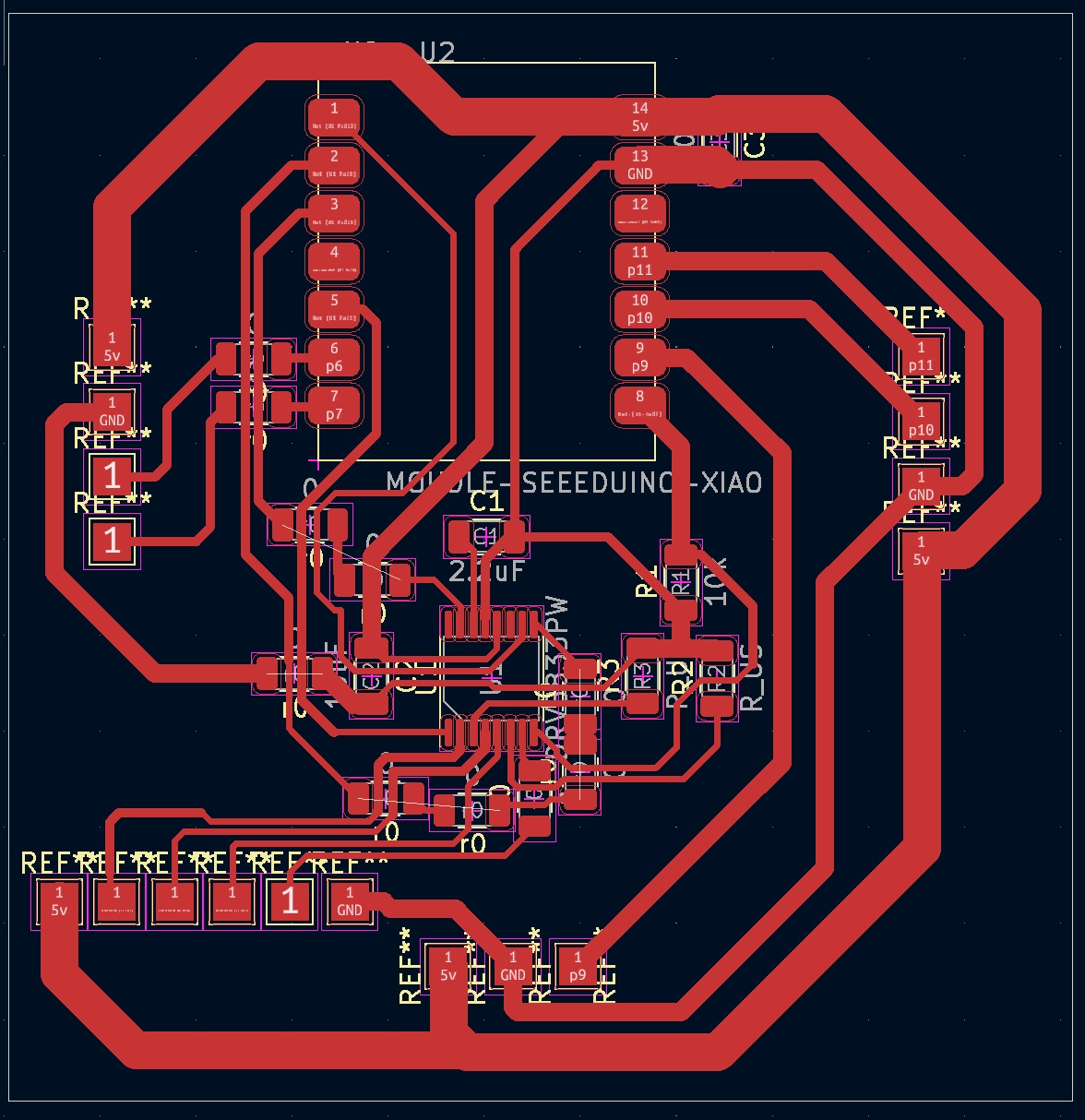 |
To create my custom PCB, I used KiCad and referred to the DRV8833 datasheet.
I went through three different design iterations for the PCB layout until I found a simple approach of "spidering" the main ICs and laying the routes according to convenience.
This strategy resulted in a compact layout without needing any jumpers.
The iterative design process taught me the importance of experimenting with different layouts and routing strategies to optimize the final board design.
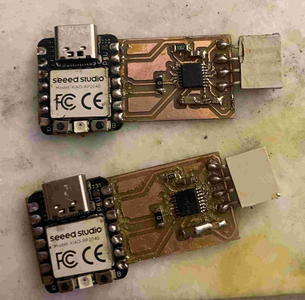
Once I had my design, I milled the PCB using different end mill sizes, such as 0.5mm and 0.125mm. I refined my milling workflow by using a 0.125mm end mill for the smallest trace spacings, a 0.5mm end mill for the rest, and a 1/32 end mill to cut out the board [insert picture of milled PCBs]. This helped me achieve clean and precise milling results, ensuring the proper functioning of the board, with little chance of shorting. |
||||
| Next, I soldered all the boards with a 750-degree iron, but I'd recommend using a 650-degree iron for custom-milled PCBs, as the higher temperature caused me to lose traces. Also, I took a shortcut due to time pressure and did not do intermittent testing while piecing the board together. Next time, I will make sure to encorporate those practices I learned from building my DAC in output week, to ensure a smoother design process. In the end, it will save me more time and frustrations in the future. I went through at least 6 different boards. Here are 5 of them: | |||||

 Please note: Some components have been removed to be up-cycled to future boards. If you do this, please test to ensure they still work after soldering, desoldering and resoldering again. |
|||||
| Upon encountering issues with my boards, I decided to build another breadboard circuit with the DRV8833 breakout board and the Xiao RP2040 Seeed. This allowed me to verify problems with lied my boards, such as ripped traces, shorts - rather than in software as I had previously encountered when first getting the motor to run using the 8833. This highlighted the importance of testing and debugging before moving on to the next step. |
 |
||||
| Having learned from these challenges, I decided to redesign the board using the drv8428 motor driver, which is used in the Urumbot. I chose this path because it would simplify the process and allow me to leverage the proven design of the Urumbot. |

|
||||
Back to Square One
| I redesigned the board using the Xiao Seeed RP2040 and DRV8428 motor driver, creating a barebones Minimum Viable Product (MVP) focused on functionality. The new design includes just the microcontroller, motor driver, and a few passive components, eliminating extra plug-in areas or unnecessary pin connections to the controller. This approach resulted in a compact board layout that contains only the essential elements needed to run a stepper motor. Once I'm confident that this controller-combo works, I can then look into adding extra core functionality to the board, and using the NEMA mount board shape. |

|
|
I've made two copies of this new design and plan to create a third one soon for the DC motor. So far, these circuits have passed the USB power test (xiao turned on and was programmable), which is promising. The next step is to test the boards with a stepper motor to ensure they can properly control it. |
| Flash forward to the next day, and the boards are not working. After debugging with my oscilloscope, I could see that the output pins were all producing the same in-sync pwm wave, which they are not supposed to do. Instead, we are looking for a phase angle of 90 degrees between the A and B pins, and the A0 and A1 should be inversely related, as well as B0 and B1. It was then I discovered I had soldered the motor controller upside-down on all of my boards! |

|
|
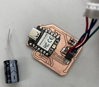
As I would need a hot-air flow to remove the chips, I worked on redesigning the board to be the same shape as the stepper motor.
Here, you can see the redesigned circuit (v4!) to the right to include the stepper motor shape, as well as through hole mounting points to add strength and stability to where the motor cable plugs in.
After soldering up, fixing a short on, and testing the new board, it was found that the xiao is not able to supply enough power in conjunction to power this motor, without an external source of power. So, future designs would probably need to rely on the drv8833 since it is much less power hungry. I verified the motor strength with a breadboard build as well, and it produced the same low-power movement. A 1000uF capacitor did little to help. It was at this point we resigned to plan Z to get our prototype up and running! |
  |
Plan Z - The Arduino Shield to the Rescue!
| We decided to go into full abstraction mode, and scale back our focus on just the needed basic functionality for this project due to time constraints. We used an arduino with a prebuilt stepper motor shield, equipped with 2 A4950 stepper motor drivers. This required an external 12V power supply, which we used a boost converter connected to usb to power it. After running a couple tests, we were able to get it moving! And powerfully too! | |

|
|
|
This script is what causes our machine to move around. It just does a simple back and forth motion across the bed, so the brush can move across the entirety of the pcb. See the results on our group documentation here! Spoiler: The milled pcb buffer works fantastically! |
|