CNC Machine (Shopbot)
The Plan
This week I tried to decide between making a pingpong table and a trophy case. As I was exploring different designs I found this design of a wooden CNC table that I could modify to include a net, but the files were already SVGs so I decided it would be very hard to modify these specific files. I also found this design of cabinet shelving that could be modified into a trophy case, which was in a simliar format. Both of these designs also used a lot of fasteners, which I'm trying to avoid if possible.
Making The Design
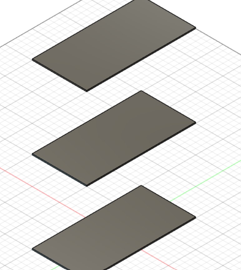
I started off by creating several User Parameters and trying to create different shelves. I made one shelf then used a rectangular pattern with the length of the pattern being the spacing between shelves mutliplied by the number of shelves. For some reason, the spacing always seemed a little to large, and I realized I had to subtract one from the number of shelves since for n shelves there are n-1 places to put things.
The first time through I made the mistake of not spending enough time planning out my design. I tried to create a parametric trophy case using tabs for connectors but was having a lot of trouble indicating which bodies created from the rectangular patterns should be combined with which shelves. I was also having trouble with offsetting tolerances in the holes using the Press Pull command then repeating that modification to all of the other holes.
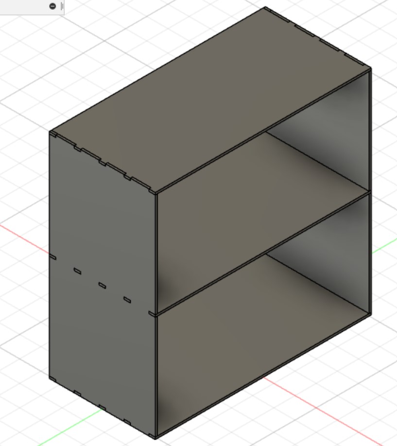
So, I decided to try again. After testing using the parameters and editing bugs, I was closer to the desired result, but still wasn't very happy with the design. One thing I had trouble with was projecting the tabbed shelf onto another sketch because if I selected one point then changed the number of tabs the point would move to a different spot. To fix this, I projected the entire body instead of a single sketch element.
Choosing Parameters
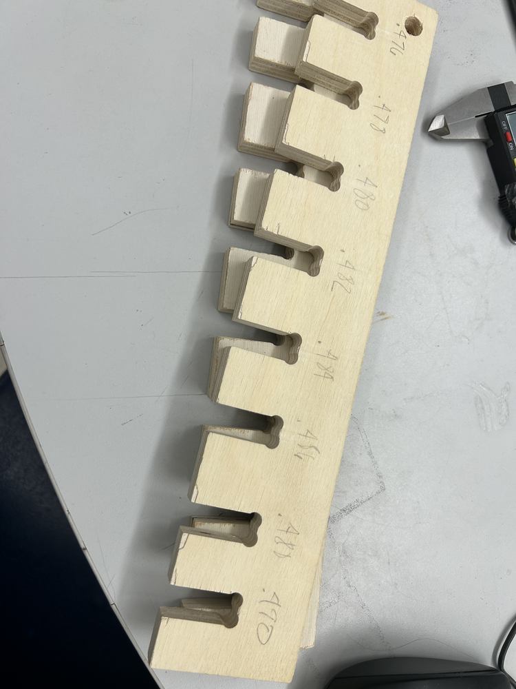
I used test clearances for press-fit joints and found that an offset of 0.01in worked very well for a tough joint that was still removable. I figured this out because I measured the wood using calipers and it was 0.479in thick, and I felt the 0.480in hole both was still enough to hold together but also was not too bad to take apart.
Design Change
I decided that this design wasn't interesting or aesthetically pleasing, and I'd like my design to be more open with less area on the walls.
I researched different designs and found several options I liked.
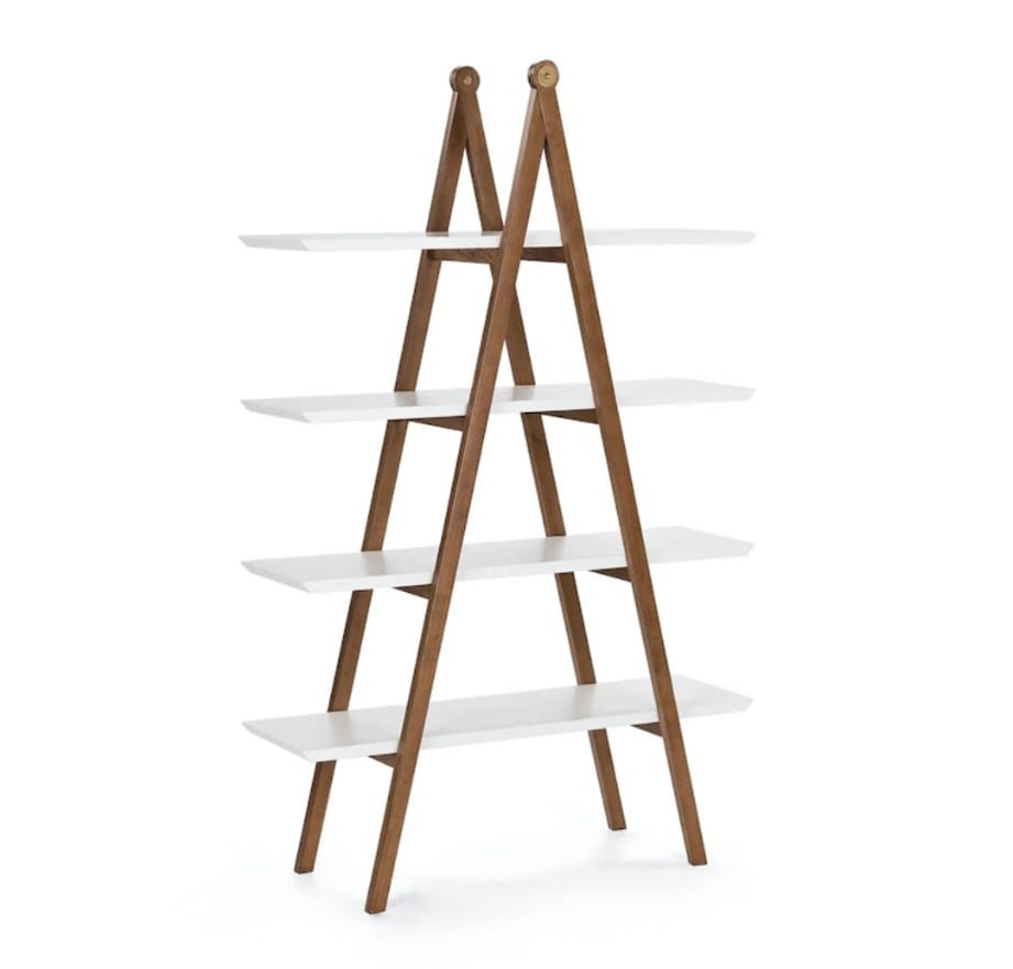
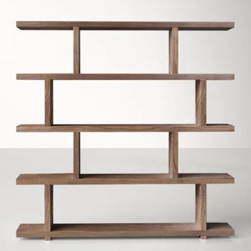
I ended up going with something similar to Option #1.
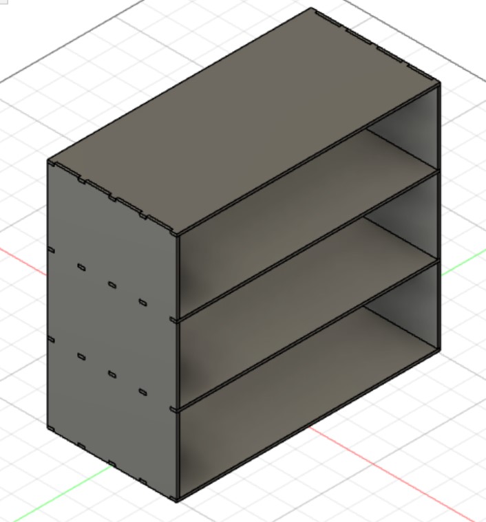
I also decided it wasn't worth my time to right now make the number of shelves parametric, so I decided on four shelves.
From the first iteration of the design, I realized that sometimes updating parameters would fail because the extrusion lengths wouldn't change. I had clicked on a different object to extrude to that object's position, but when the object moved, the extrusion didn't for somereason. I learned that in the dialogue box for the extrusion I had to change the extrusion type to To Object then click the object I wanted it to extrude to for the design to continue functioning when the parameters are updated.
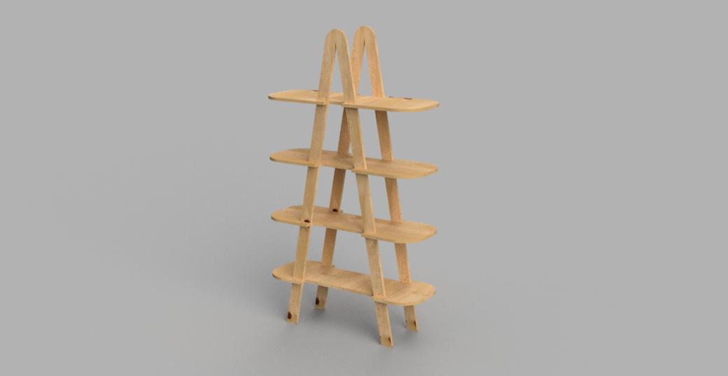
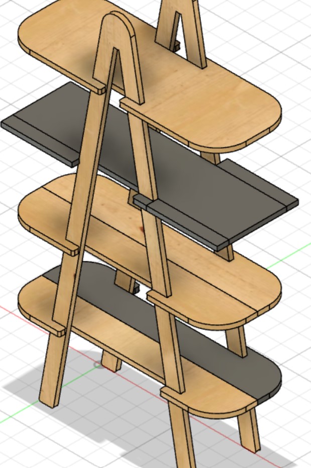
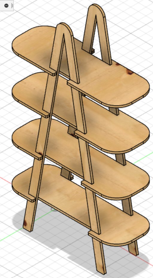
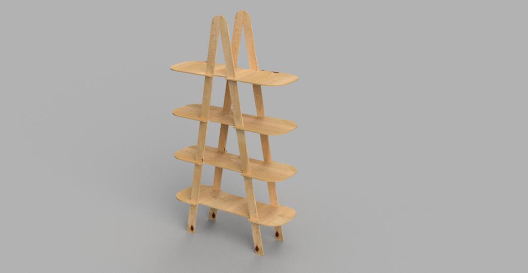
I then rendered my design.
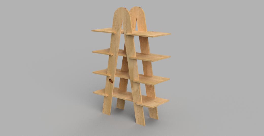
I added fillets.
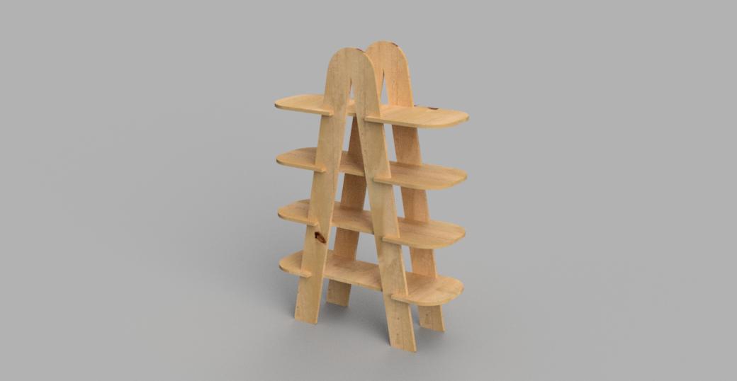
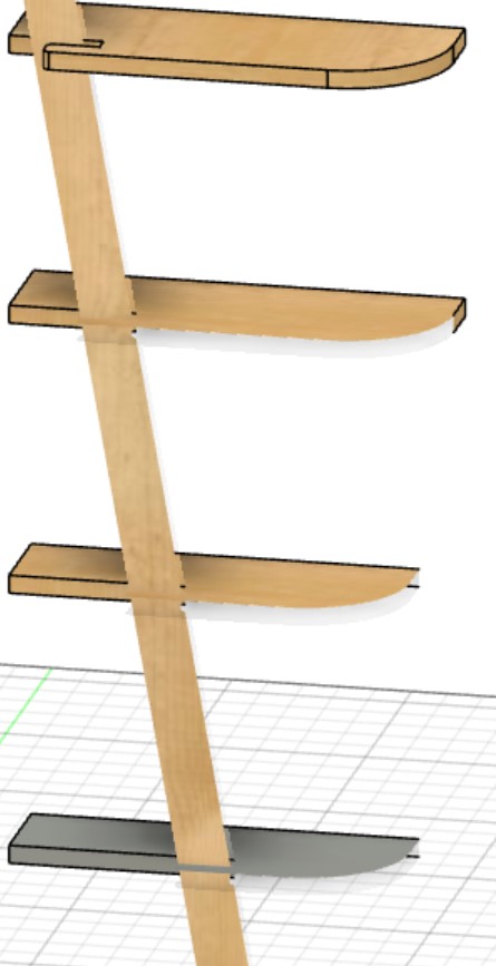
I made the legs thinner so the trophies wouldn't be blocked.
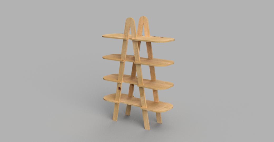
I made it taller.
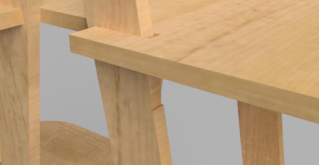
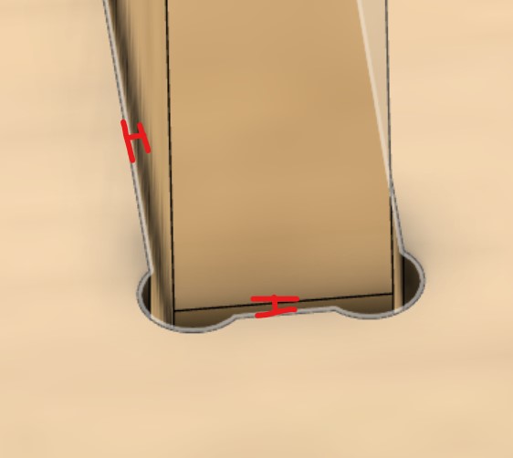
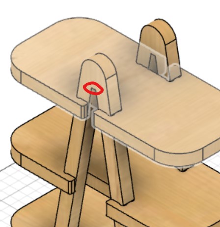
And here's a rendering of the attachment mechanism I created - the pieces will slot right into the vertical cut-out in the frame of the design and won't be able to slip down because the rest of the frame widens too much.
Animating
Next I went to the animation workspace and tried to animate an assembly of my design. At first I could move anything individually because I hadn't moved the bodies to their own components. I moved each body to its own component with Create Components from Bodies when right-clicking the body in the hierarchy.
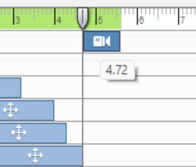
To try to have a pause between two different movements of the camera I tried making a keyframe but couldn't figure out how. I tried this because I'm familiar with Adobe Premiere Pro and this is how animations are handled in that software. However, I just tried making the animation without the keyframe then I was able to drag around the bar in the timeline to change where it started.
I also didn't like how the end of the animation stopped right after the last thing moved. I could make something ever so slightly move after a couple seconds, but I instead found this article which suggested using the TimeStrecher tool. I then realized this article wasn't for Fusion 360 and had to find another approach. I tried exporting it to see if this extra time was added automatically, but it wasn't. At this point I'm wasting time so I just decided to move a piece covered by another piece several seconds after the end of the animation. This worked! The file is too large to embed or upload in this week's files, but you can use this link to watch or download the animation (I created the link by saving the animation to the cloud when exporting instead of my local computer).
I had weird problem where at a random point in the animation the camera would move when I didn't see anything in the timeline. I also noticed I couldn't drag camera animations on top of the point at which the strange movement was happening. After trying to figure it out for a while I decided to just cut the animation short before this happened.
Dogbone
Talked Mr. Dubick and realizd I needed a dogbone on each of the shelves becuase the milling machine is incapable of cutting sharp angles, and if I didn't add them, the shelf would catch onto the frame too high up.
I watched this tutorial on how to install and use this extension in Fusion 360. The link for the installation guide from the tutorial wasn't working so I found this one instead. I wasn't sure how to open the %appdata% folder, but this article taught me I simply need to type %appdata% into the address bar in File Explorer. I realized that I also could have used these installation instructions linked on the README file of the Add-In. The folder I copied was the one inside of the one that I downloaded. My file structure was Dogbone-master > Dogbone-master > *other files* so I used renamed the second Dogbone-master to Dogbone. I then opened Utilities > ADD-INS > Scripts and Add-Ins... in Fusion 360, clicked the Add-Ins tab, clicked Dogbone, then pressed Run. I didn't even need to restart Fusion 360 for the Add-In to appear! I then found the command under the Create dropdown (or just with the shortcut box), and it worked! I set the tool diameter to a newly-created User Parameter called ToolDiameter set to 0.25in for now. It took a while to select all of the edges by hand, but it would take longer to figure out how to do it automatically.
I also heard that some other extensions can apply the dogbone to entire bodies or components, but inputing a body into the Add-In gave an error when I tried to run it.
Cutting Out
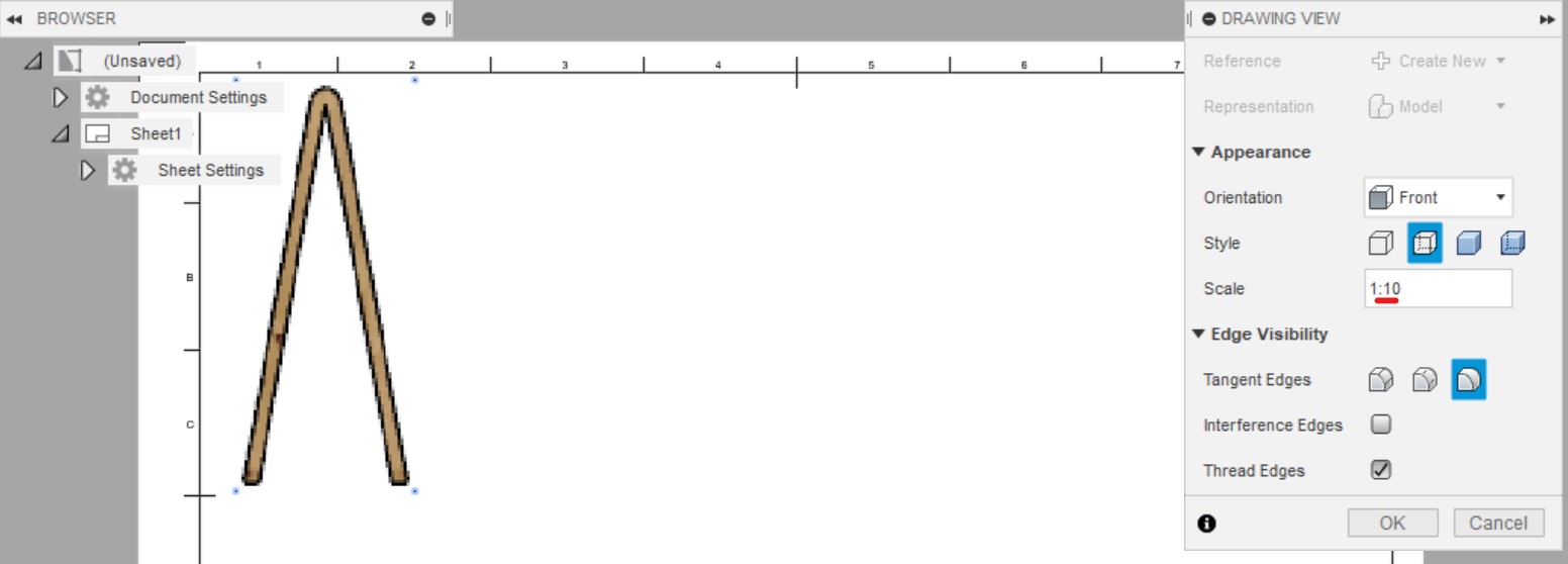
To cut out a carboard test of the final design, instead of changing the parameters, I simply made the ratio 1:10 when exporting the drawing.
My CorelDRAW free-trial expired so I used Inkscape. Did 0.001in for hairline. I expoted as an SVG file.
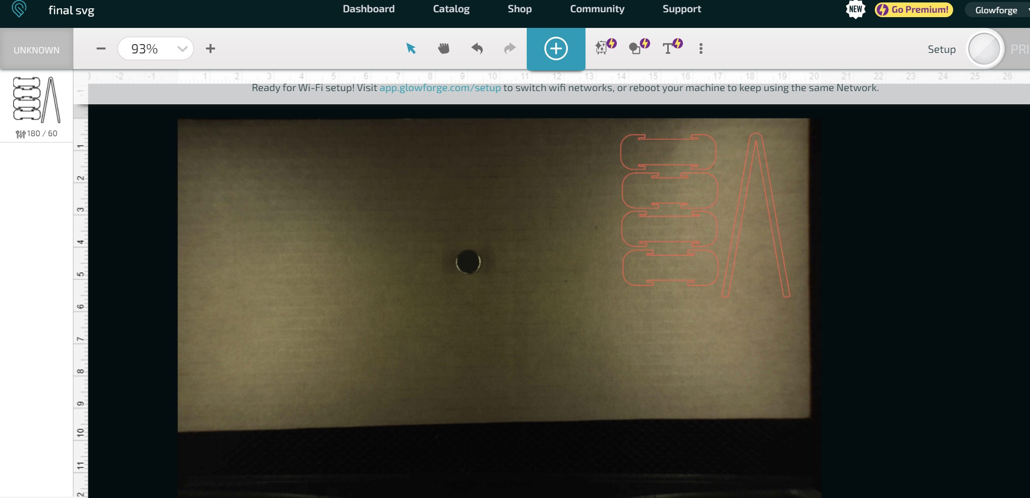
I realized I didn't account for the thickness of the material being divided by 10, so I changed the parameters to where MaterialThickness was 1.25in so it would be 0.125in (the thickness of the cardboard) when exported into the drawing. I then made the drawings and repeated the exporting process.
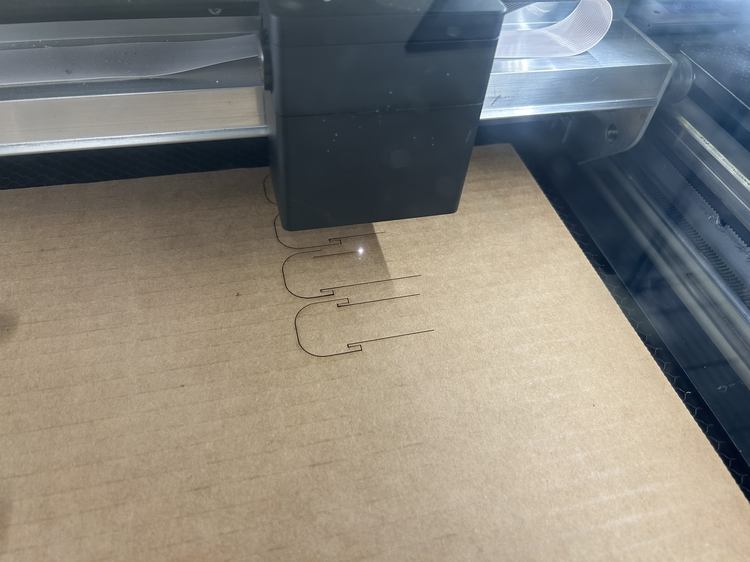
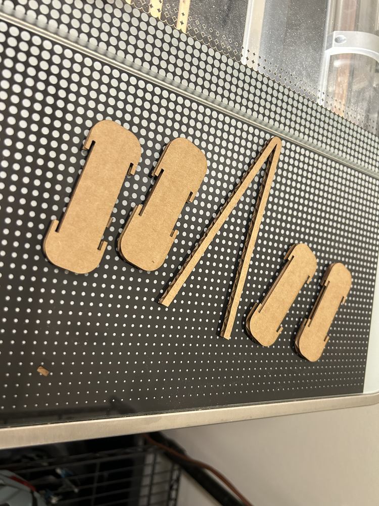
This worked but since I had no tolerance it was very hard to fit on and many of the little cardboard tabs were bent. Even so, it assured me that my design will work!
Design Modifications
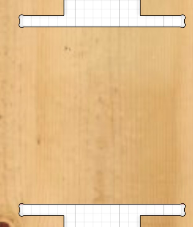
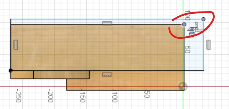
I added tolerances as two User Parameters and will use the combs to test what tolerance to use.
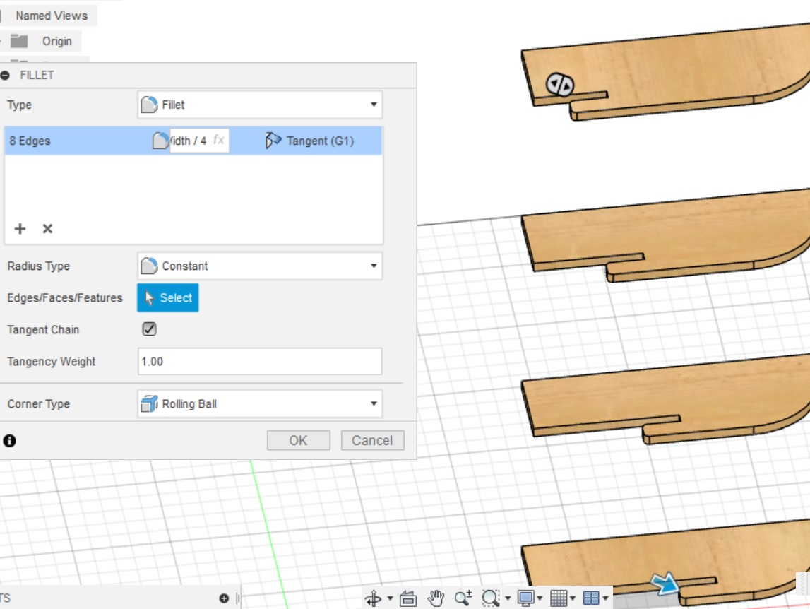
I also added fillets with radius OverhangWidth/4 before mirroring in the timeline.
More Design Modifications
I added a dogbone for the notches on the frame. I'm worried these will be too small compared to the tool diameter, but I'll leave it for when I test on the smaller milling machine.
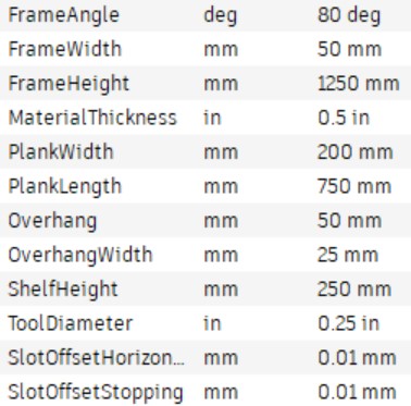
I decided that, in order to preserve the current ratios of my design, I'd make all parameters ratios dependent on the height parameters. Here is the old parameters.
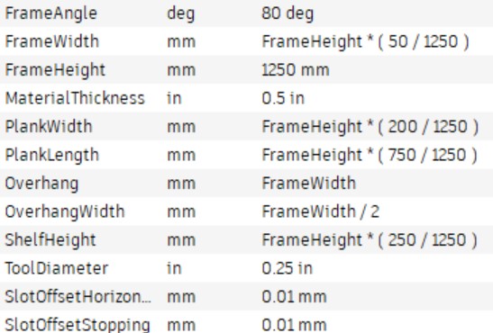
Here are the updated ones.
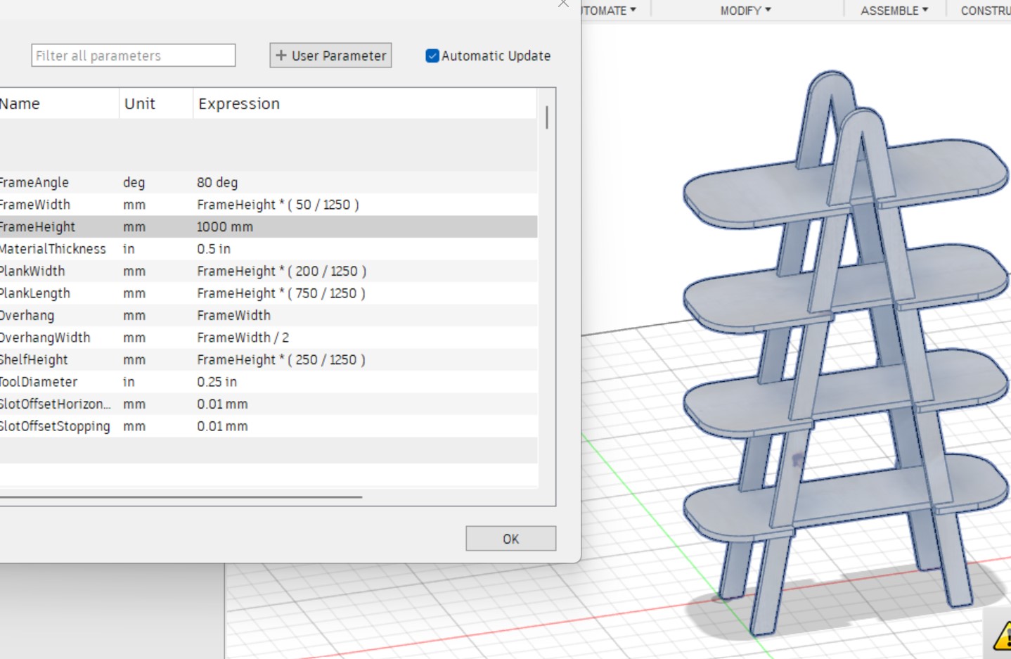
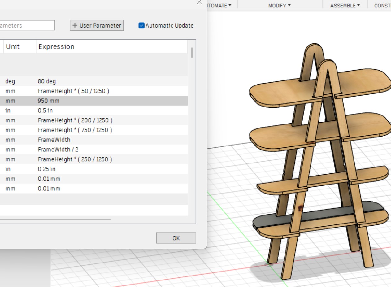
This worked when I scaled the height down to 1000mm but failed at 950mm.
I set the height to 999mm and noticed there was a tiny gap in the shelf after the mirror command (also the appearance was removed for the bottom shelf only).
I looked back in the timeline but couldn't figure out why there was a gap. I assumed it might have been from rounding error from the parameter calculations. If this was true, the distance should change as the height gets smaller, soI changed the height to 900mm and the gap got larger, and weird things happened when I went back in the timeline.
I moved the height back to 1000mm, saved, then restarted Fusion 360. I then changed it back to 999mm and got different, stranger results.
I realized that the top two shelves did not have parametrically defined widths, and the projection was also messed up, so I went through and either made points concident with projected points from other shelves or directly repeated the parametric values from the other shelves' dimensions.
After going through and redefining all features that dependend on the top two shelves, I added a parameter called FirstShelfHeight for the hegiht of the first shelf becuase it broke around 600mm, and I noticed that it was because the shelves went above the frame. I made the parameter dependent on the FrameHeight parameter.
Around 200mm the design just got too small for the thickness I had set, but this isn't a problem since I likely won't be making a version of the design that small.
The dogbone at end of the timeline was messed up, so I redefined the edges and moved it before the two mirrors so that I wouldn't have to select as many edges.
I then noticed the top of the frames had a weird shape.
I realized that the first sketch got messed up when changing the height so I recreated one of the lines that was lost and corrected the profiles to be extruded, and it worked!
Then I scaled back down and up from 350mm to 1250mm, and it went back to being incorrect. I tried different strategies to get it to stay, and when I managed to do so, I recieved a bunch of errors when I scaled the design down again.
I then decided to leave it with the incorrect one then at the end of the design extruded a cut of where it should have been. I then realized that I needed a fillet the diameter of the tool to be able to cut out the frame. When I scaled down and up sometimes the problem went away then I got problems with the new extrusion since there was nothing wrong. I tried making the wrong initial design permanent by modifying the sketch but I then got loads of errors when I scaled it up again. I just decided to leave it as it is and then make small modifications of the extrusion profiles if necessary before exporting. I also added all of the appearances back that had been lost with the errors.
Test On Smaller Mill
I had a 200mmX200mm piece of 0.2in thick plywood for testing, so I set the height parameter to 200mm and the material thickness to 0.2in.
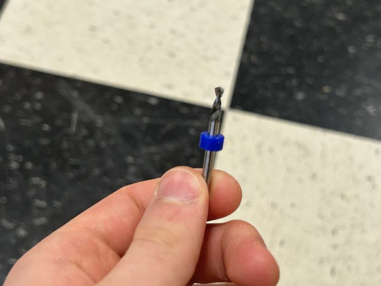
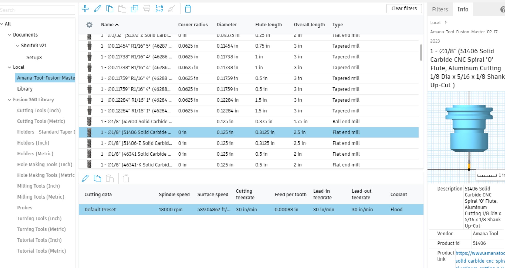
I chose a 1/8" end mill so I set the ToolDiameter parameter to 0.125in.
Fusion 360 Toolpaths
I watched this tutorial to learn how to create toolpaths in Fusion 360. I noticed that the CAM workspace had been replaced with the Manufacture workspace in newer versions of Fusion 360.
This tutorial (~03:21) revealed to be that I can create multiple setups for different components of my design.
I used this video to help me install this tool library in Fusion 360.
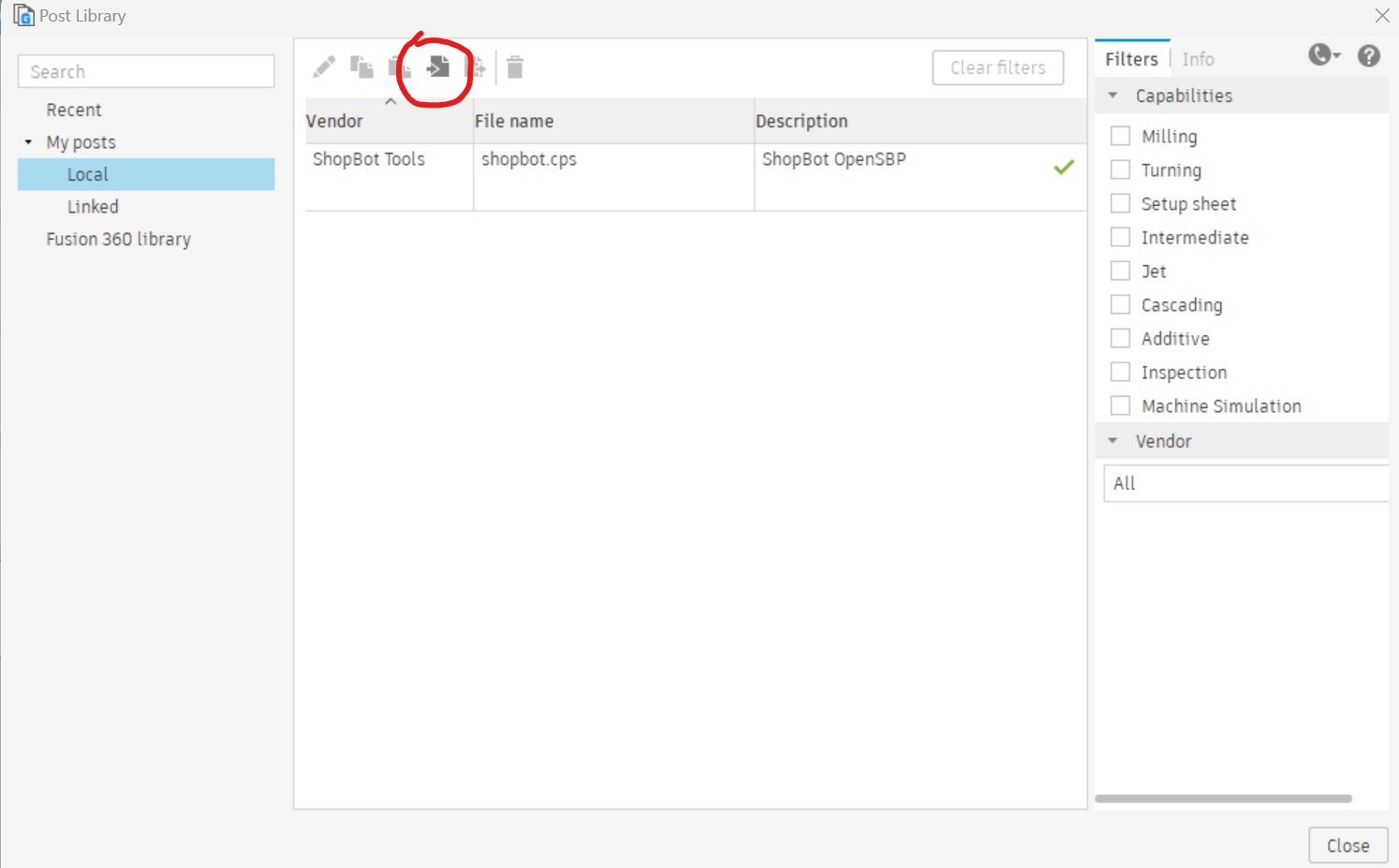
I also searched for Post Library and installed this library.
I created a new setup and selected one of the frames as the model. The machine I'm using is a Genmitsu 3020-Pro Max, but I didn't see this as an option. I also tried looking at this tutorial
After searching all around for the specs for the feedrate of the Genmitsu 3020-Pro Max which, for some reason, wasn't listed on this datasheet, I found this tutorial which walks through settings up Fusion 360 for the Genmitsu 3018 milling machine, and they didn't even select a machine! I realized this setting probably wasn't even necessary so I continued to follow along with these steps.
I selected one of the frames as the Model and turned off visibility on the other components. I set the WCS origin to the top face of the bottom-left corner with x and y axis hugging and z pointing up.
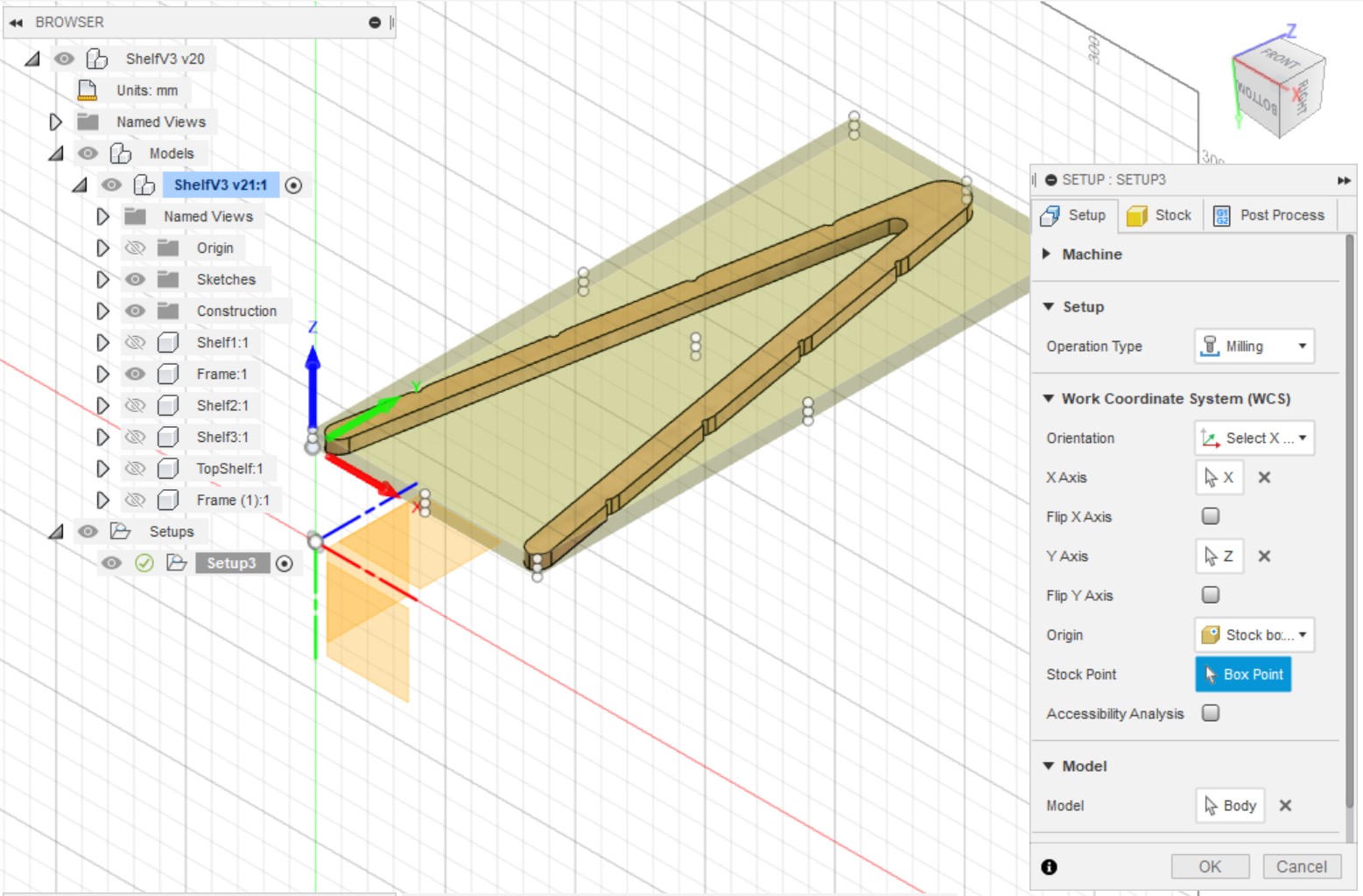
Under the Stock tab I set the z to 0.2in and left the x and y dimensions at their default values. I then pressed OK.
I don't have any pockets in my design, so I skipped to Step 3 in the tutorial. I selected 2D > 2D Contour and set the Coolant to Disabled. I selected the following bit because it was closest to the one I have and measured, although I couldn't find an exact match for 1/8" diameter, 0.375in flute length, 1.5in overall length. Since the bit I used came in this set I also chose one whose material was Carbide. I guess I'll see later if this bit setting works or not. Beyond this I left the default settings.
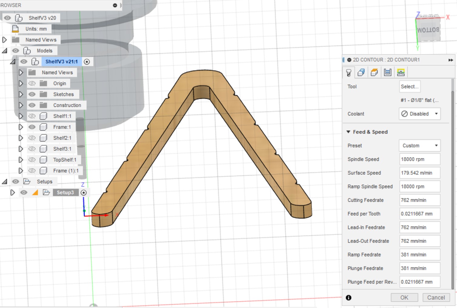
I then selected the bottom edge of the frame for the contour and turned on tabs.
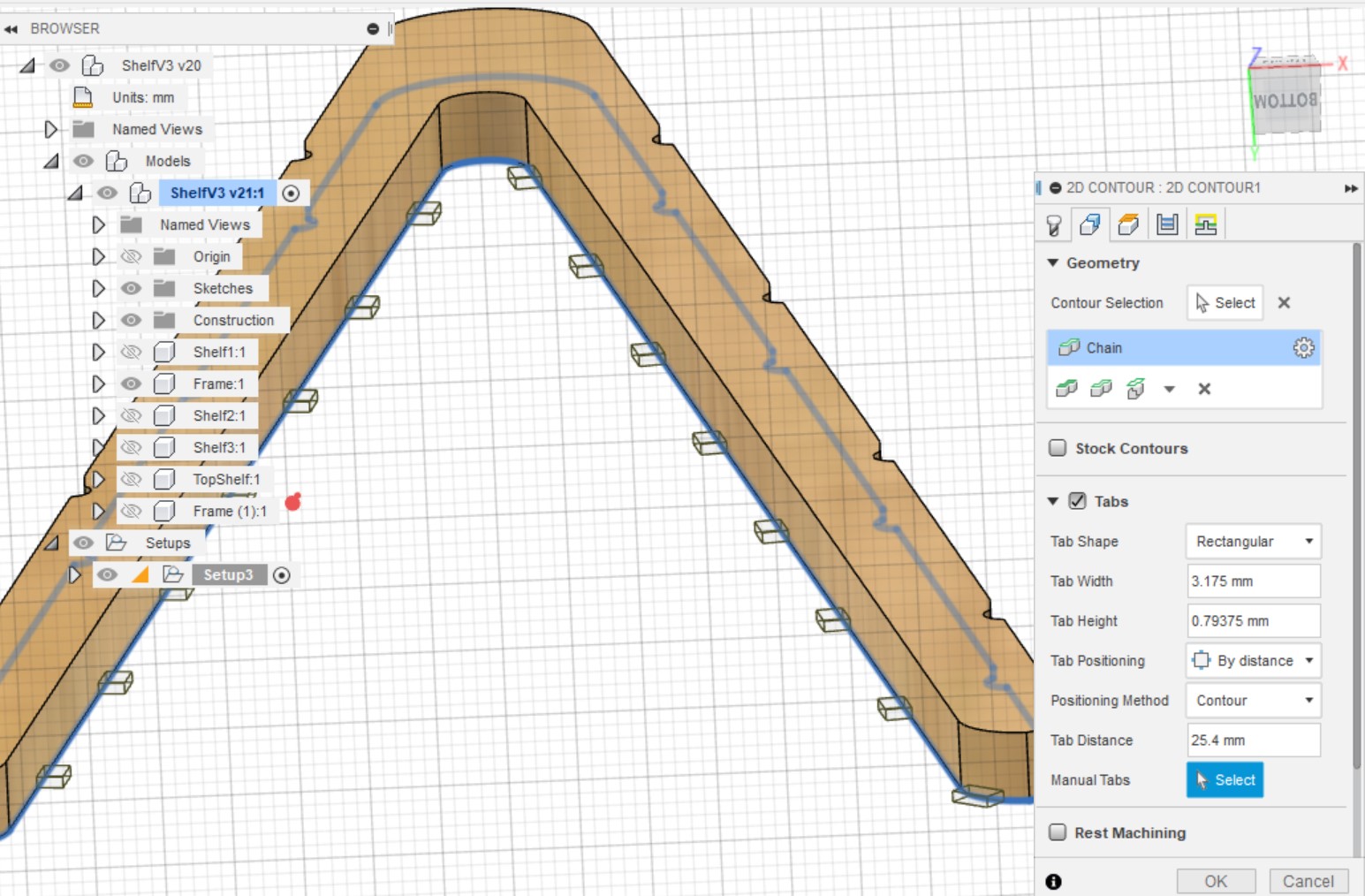
I left the rest of the settings and pressed OK.
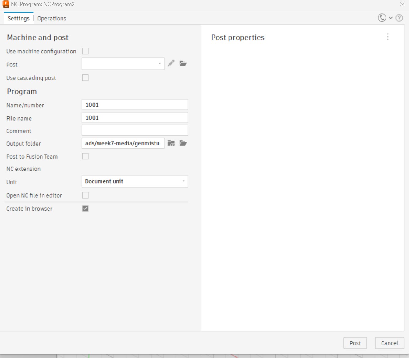
I then opened the Post Process window. I left the default settings and selected my output folder.
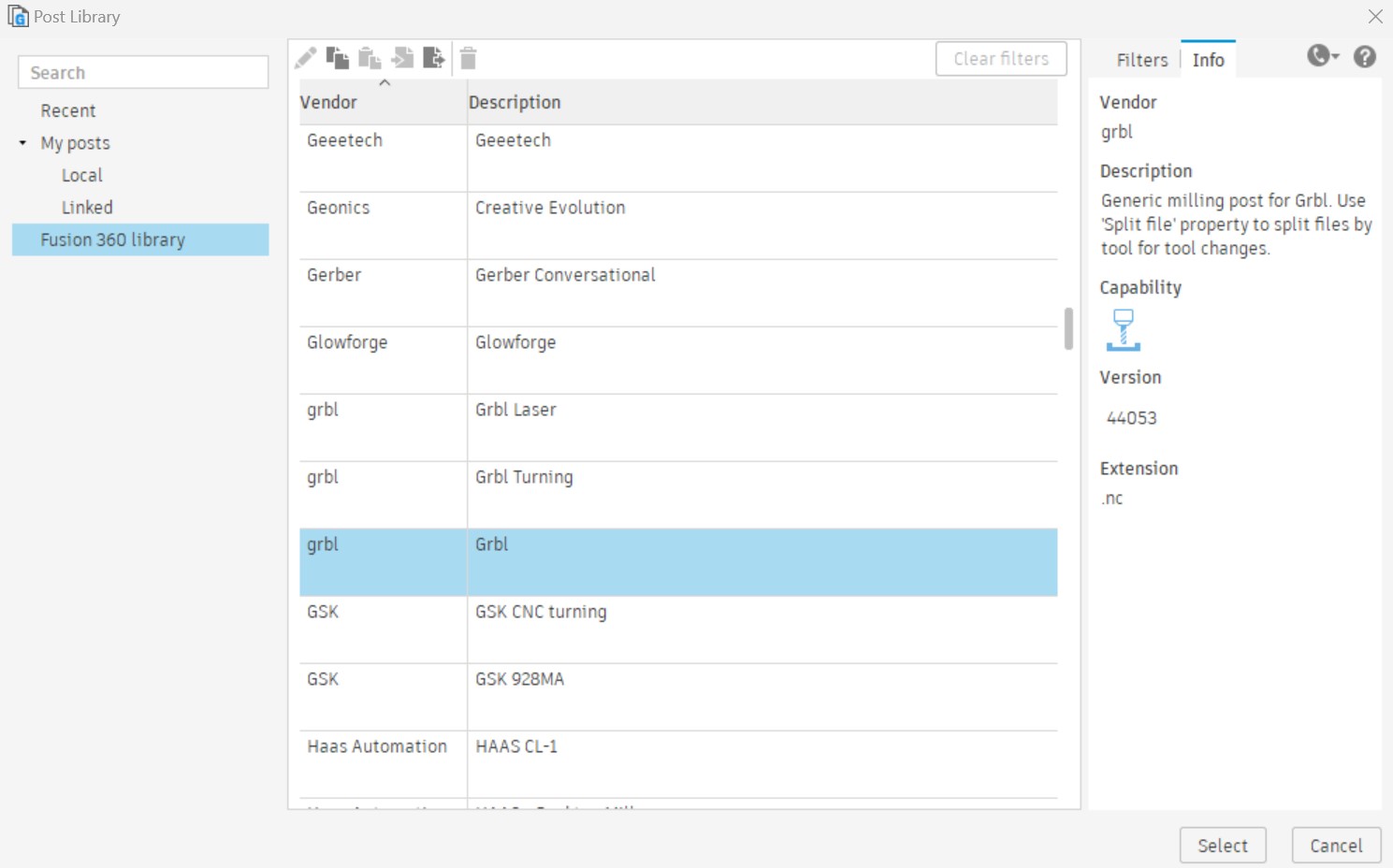
I then got an error that I had to select a post processor. I wasn't sure what to select so I chose GRBL like the tutorial did for the 3018 machine.
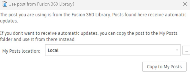
I then recieved the following popup, so I just selected the Local folder in the post processing libraries.
I then pressed POST.
Running The Job
I copied the generated NC file to a USB drive.
I clamped two pieces of wood onto the CNC machine - a 200mmX200mm piece of plywood and another larger piece of scrap wood underneath.
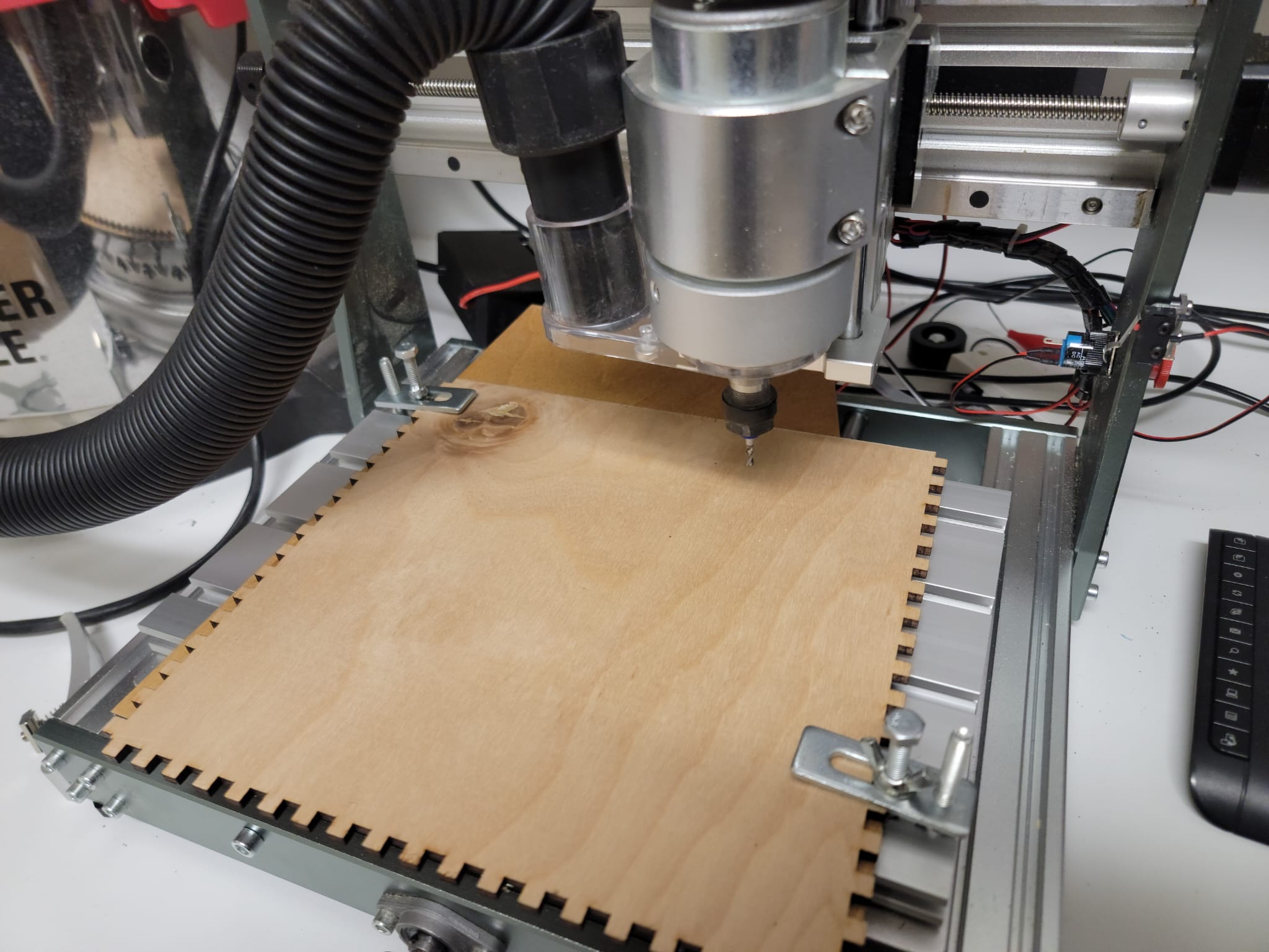
I opened the Candle software on a computer connected to a Gemitsu 3020-Pro Max CNC machine. I clicked the unlock button to change the state from Alarm to Idle, but when I tried to jog the bottom material, there was a very strange sound. I took apart the motor and realized that the motor was slipping, so I tightened the bolts on the shaft around the motor and the problem was solved.
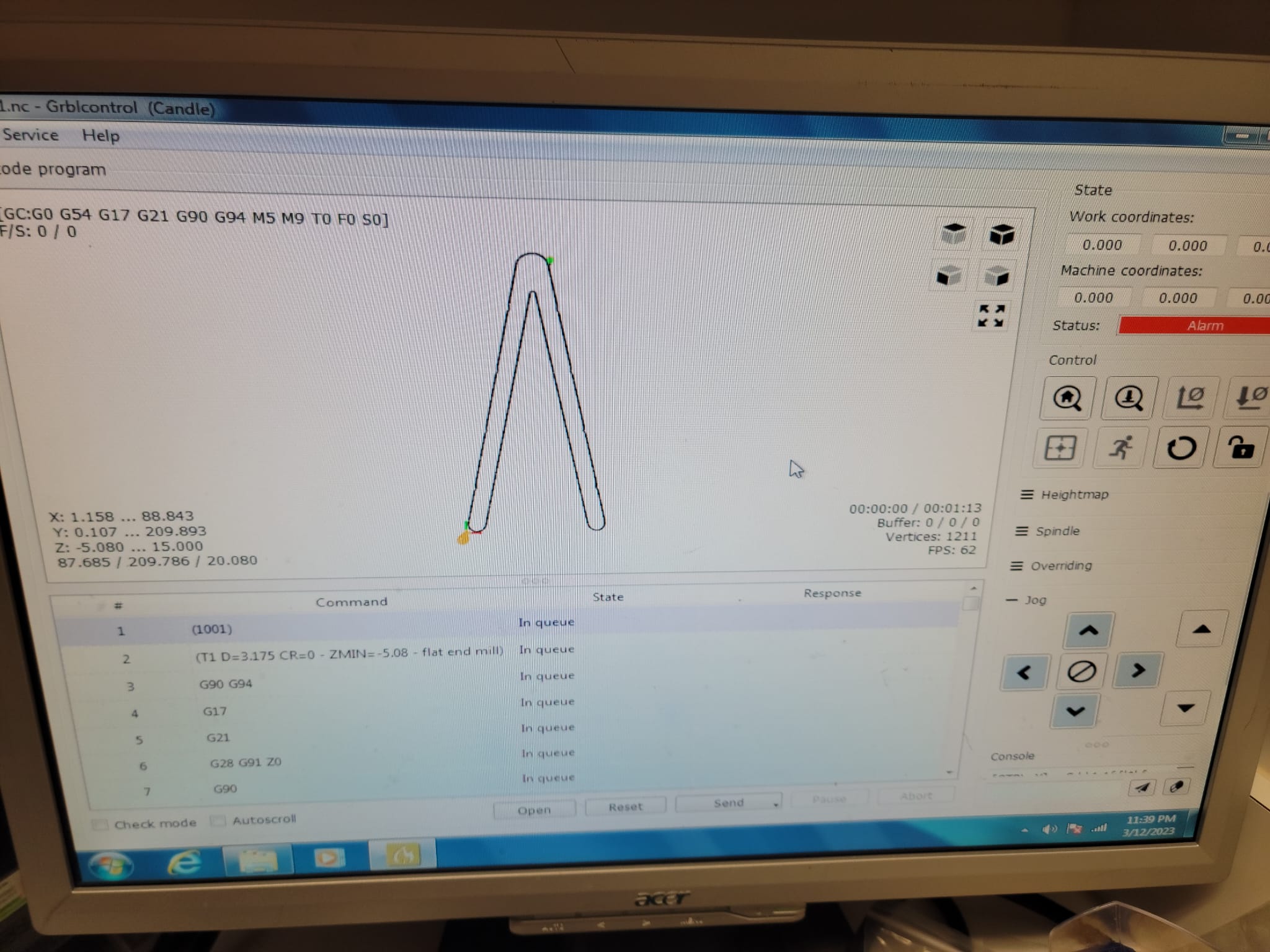
I opened the generated NC file and manually moved the x, y, and z axes to the origin position for my design, but I moved the z higher so that I could run a test cut without running into the material. I made sure not to move it too high so that it would set off the emergency stop.
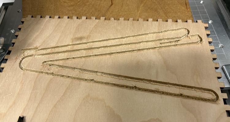
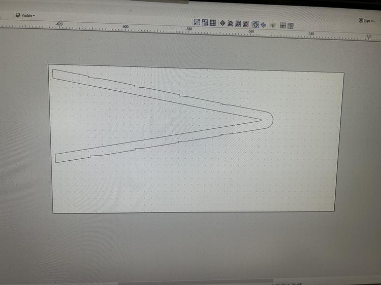
When I did the air cut, I realized that the height of my design was too large for the machine to cut. So in Fusion 360 I changed the x and y axis definitions to that the model would be rotated 90 degrees in Candle. I exported this file and imported into Candle and it worked! For some reason the cut started far away from the origin point so the cut intersected a previous failed cut where the wood slipped, and it didn't cut all the way through.
Aspire
Learning Aspire
I watched this tutorial to learn how to export Fusion 360 models into Aspire.
In The Lab
CAM in Aspire
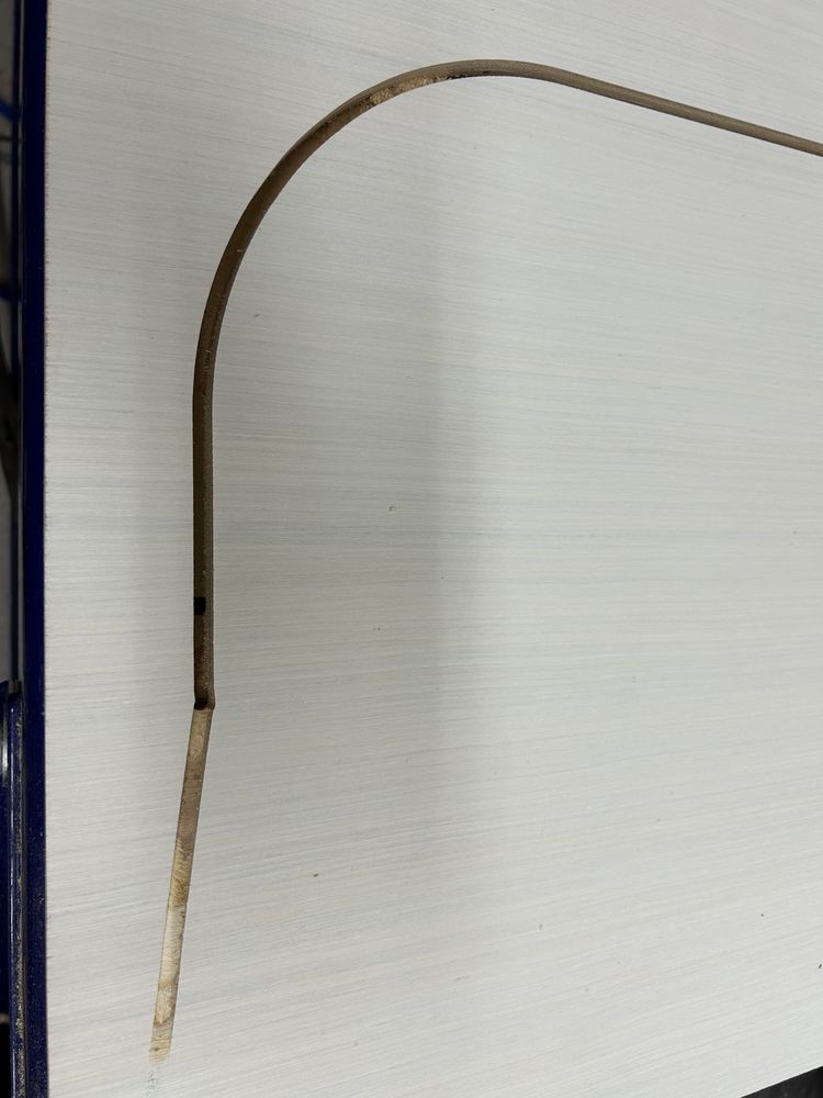
I used the press-fit joint testing combs and measured them to be 0.471in thick. The 0.478in wide hole worked the best for sliding all the way down which makes a 0.0035in tolerance/offset on each side or 0.0889mm. I also liked the 0.482in width for the end of the mechanism which makes 0.0055in tolerance/offset on each side or 0.1397mm.
I decided to make the frame 1.75m tall so I changed the height parameter to 1750mm.
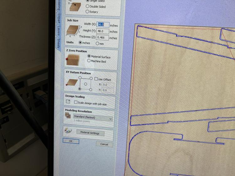
The plywood is 96inx48in.
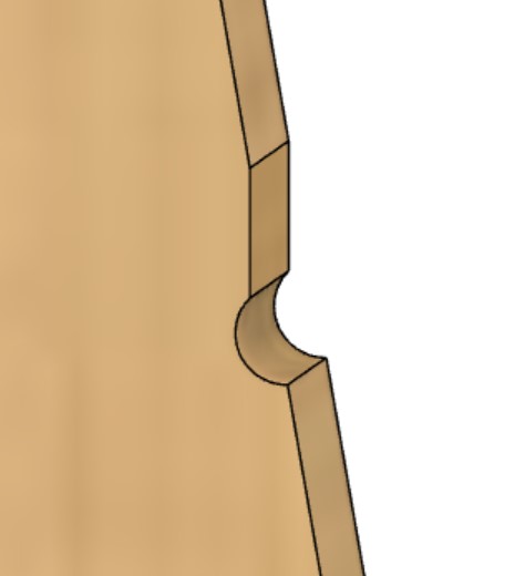
I discussed my design with Mr. Budzichowski who told me that, since the dogbone on the frames created a hook instead of a ledge with the 1/4" bit, the shelves wouldn't lay flat. He suggested that I move the notch farther back so there'd be more of a ledge. To make sure the design was still aesthetically pleasing I added a long fillet (I can make it parametric later) and redefined many of the later features that dependend on this part of the design.
After exporting several DXF files I realized that the dogbones on the shelves disappeared! I tried adding them agains in Fusion 360, but for some reason I could select any edge but the ones I needed. I realized it was because, after creating a fillet I set the fillet as the object to extrude to, and since the object was curved I recieved strange results. I moved the fillet to after the dogbone, and it worked!
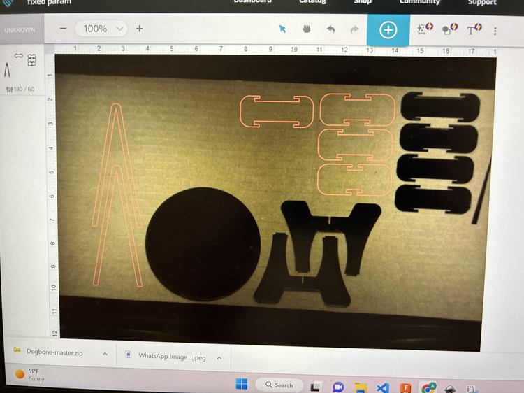
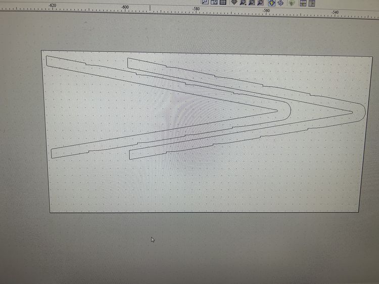
After fixing the design, I exported a DXF file of the frame in a 1:1 ratio from Fusion 360 then uploaded it to Google Drive. I downloaded on a computer with Aspire and opened it using the Open Existing File option. When I set my document to the correct dimensions, the cut became very big, so to fix it, this tutorial I selected everything I imported, clicked the Set Size command, set the anchor to the bottom right, and wrote *i in the Width (X) input field. I then rotated it holding alt to where it was horizontal.
Then I copied and pasted it.
I then realized that the dogbones were gone on the frames! So I undid the copies and tried to create a dogbone in Aspire with the settings set to a 1/4" tool. The Dogbone Fillet in Aspire didn't work, I think because it was only one corner, so I went back and fixed Fusion 360.
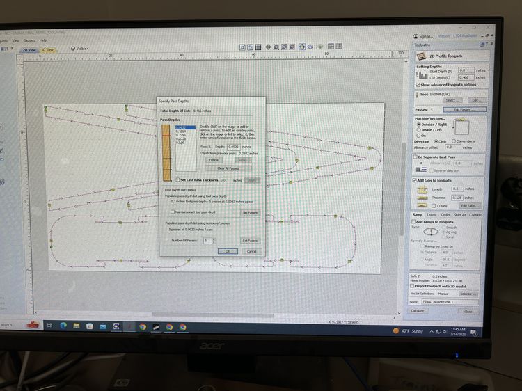
In Aspire, I set the Feed Rate to 250in/min and the Plunge Rate to 20in/min.
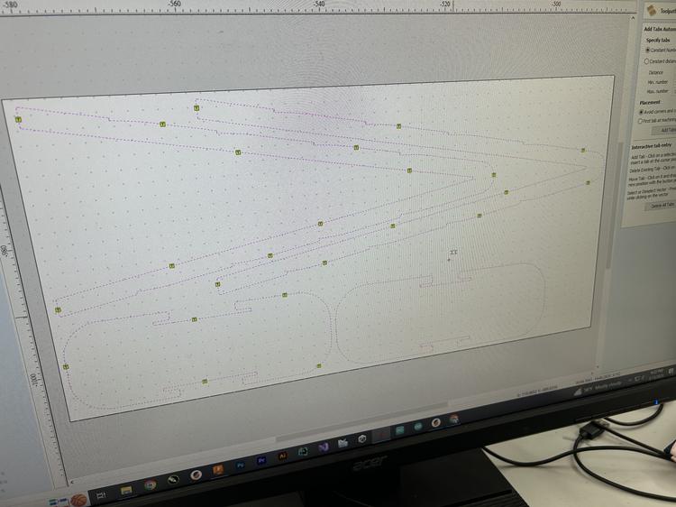
Then I addedd tabs manually. Mr. Dubick showed me where to place my tabs, making sure they were in more flat areas.
I moved the frames so that they weren't so close together then clicked Calculate. I got a warning about open contour but clicked OK.
There were many red lines in the result, so I think I didn't make each shape an individual profile.
In 2D View I right-clicked the profile and pressed Delete This.
I then went through each shape and grouped it with ctrl + g. I reset the feed and plunge rates, but when I recalculated the toolpaths, this didn't work. So, with help from this source, I ungrouped each part one at a time, selected all contours, used the Join command to create a single path.
I had to redo the tabs, and I noticed that the origin was set very high and to the right, so I clicked the Set Job Dimensions and Origin menu and unchecked the Use Offset option.
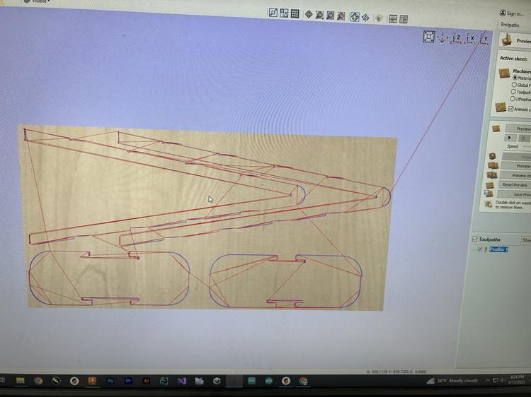
I thne pressed Preview Visible Toolpaths to see a preview, which I was happy with.
Preview Visible Toolpaths to see a preview, which looked good. I clicked File > Save As and uploaded the file to Google Drive.
I repeated these steps for the other two shelves for which I'm sharing a piece of plywood with Griffin Orsinger and Dylan Ferro.
I then chose a piece of wood I'd use and measured it in a few spots, for which I found an average of 0.466in for both pieces of wood. I updated the design in Fusion 360, re-exported and imported, and in the Set Job Dimensions and Origin menu as well as in the profile settings I updated the cut depth/material thickness in Aspire.
I then saved everything and uploded it to Google Drive!
Using Fusion 360
Mr. Nelson helped me learn how to use Fusion 360 to export CNC toolpaths. I learned that I can select any tool as long as the diameter is correct, that I should set the Clearance Height to 2in, Retract Height to 0.5in, Bottom Height to -0.02in to make sure the cut goes all the way through, and the Lead-In Sweep Angle to 0 deg for softwoods.
Learning How To Operate The Shopbot
This is the workflow for operating the Shopbot.
I watched Mr. Dubick walk Ryan Kim through using the Shopbot and now understand how to operating the machine.
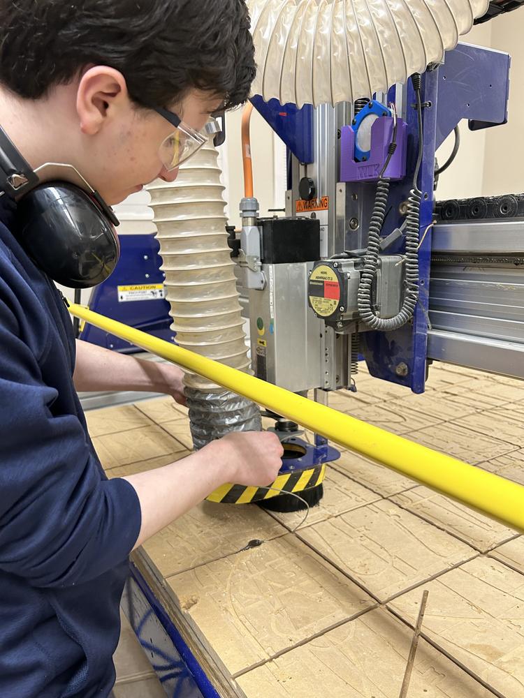
Operating the Shopbot
I downloaded my Aspire files and opened them on the Shopbot. Following the workflow, and with help from Ms. Dhiman, I exported the toolpath, jogged the machine to (0, 0) with J2, 0,0, moved the z-axis to 3 with JZ, 3.
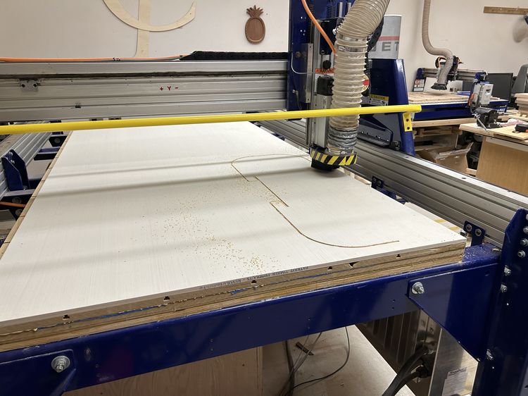
I then put my sheet of 48inX96inX0.466in plywood on the machine bed and used the nail gun to hold it down, making sure I didn't nail where the final product would be cut out and where there isn't a hole in the machine bed.
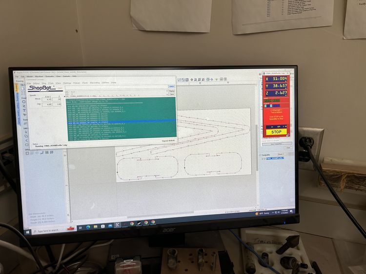
Then I opened the Shopbot software and selected FILE-LOAD. I clicked on the toolpath then selected 1 - 3D Offset to carry out an air cut to make sure the design was alright. I pressed enter, turned the key in the machine, pressed the green button, then pressed OK to start the cut. The cut moved slightly off of the side and top of the plywood during the aircut, but I thought it would all be fine during the actual cut, and if worst comes to worst, I could simply sand the edges to retain the filleted shape.
I then realized that I hadn't calibrated the z-axis of the machine on the bed, but since someone had cut and calibrated right before me, the settings should have stayed the same. Even so, just to make sure, I moved the bit to where the machine bed was exposed without the plywood and moved the z down to zero, holding my hand over the space button in case it moved too far down. This worked perfectly, so I was confident that the z-axis was correctly calibrated.
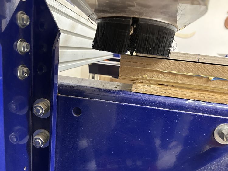
I then repeated the steps for loading the toolpath into the Shopbot software and moved the 1/4" bit back to (0, 0, 3), left the offset as no offset, pressed enter, made sure the key was turned, pressed the green button, then pressed OK. The ramp looked good, then the bit immediately moved down through the material and cut all the way through in one cut. I stopped it halfway through the first piece and was stumped by the behavior since the air cut was done in layers. I also checked the advanced toolpath settings in Aspire which confirmed that my design was set to cut in layers. Then Ms. Dhiman pointed out to me that I had Material Surface selected as the Z Zero Position instead of Machine Bed.
After fixing this, I repeated the steps for setting up the cut, and as the cut reached the part that hadn't been cut out, CRACK! I immediately pressed the space bar and stopped the cut. It turns out I had pressed the green button a split second before Ms. Dhiman turned the key and the bit never started spinning, causing it to snap in half when it started cutting the material.
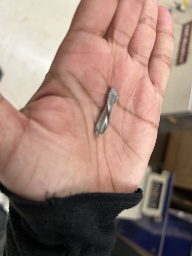
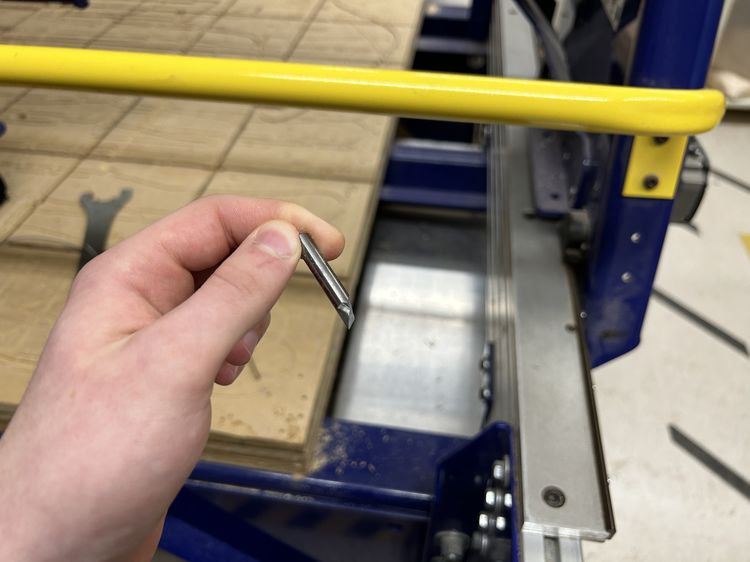
We jogged the bit up, removed it, and replaced it with another 1/4" Flat End Mill.
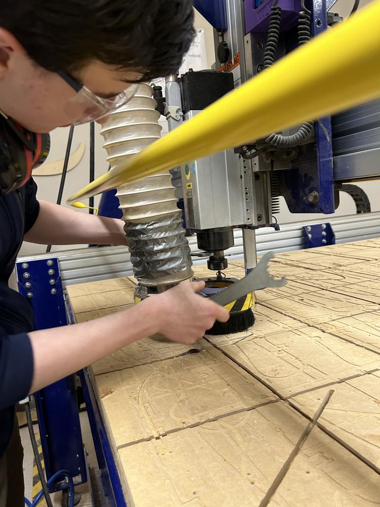
Then we ripped the plywood out of the nails holding it down and snapped the leftover nails then hammered remaining pieces into the machine bed. Then I used the C2 command and the metal pad to re-calibrate the z-axis.
I found a new piece of plywood that was 0.462in wide, put it on the bed, and nailed it down. I then modified the settings in Aspire to match the new material thickness, but I didn't update the design in Fusion 360 since I didn't think 0.004in would make a difference, especially after sanding.
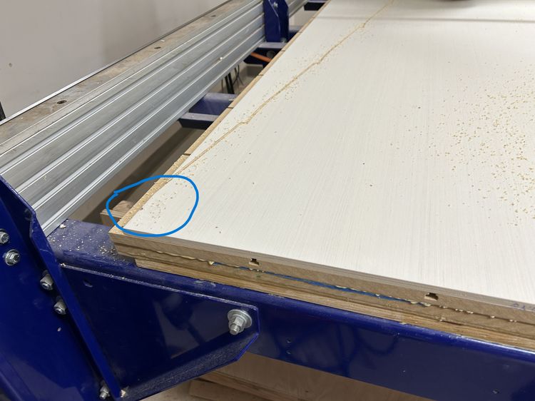
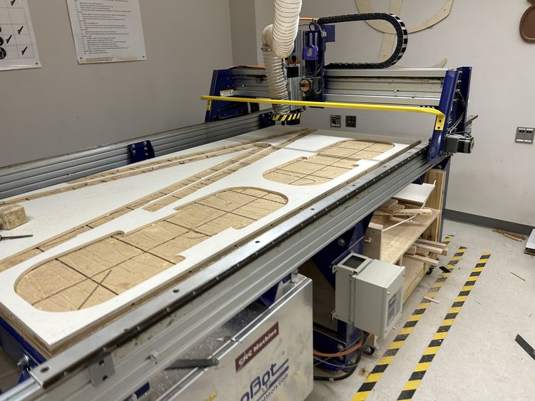
This time it worked! The only issue was that the bit went off of the plywood on one side and on the top of the design. In the future I'll offset the cut slightly based off of the air cut's results if it's anywhere near the edge, especially since I had more room on the other sides, but for now it's fine, and I'll sand those edges.
For the two shelves that I couldn't fit on the plywood I shared a second sheet with Griffin Orsinger and Dylan Ferro. This cut went very smoothly and, applying the learnings from the last cut, we encountered no problems.
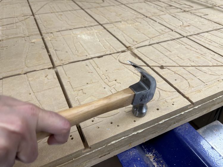
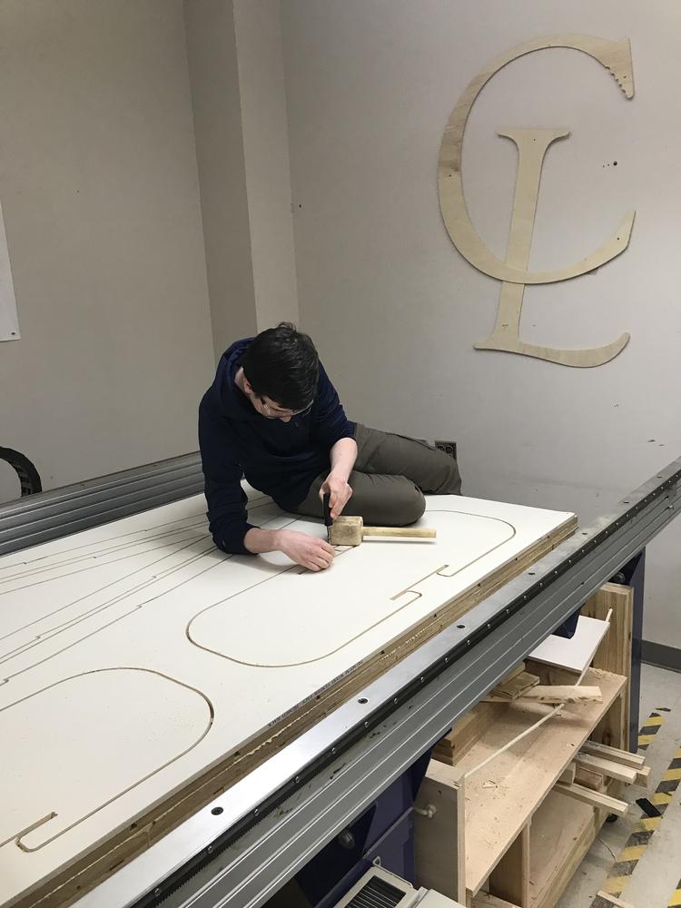
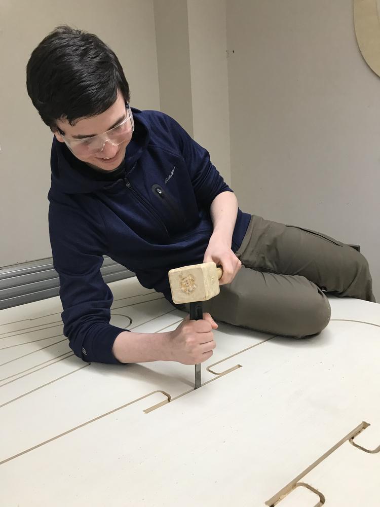
Removing The Pieces
I used a chistle and wooden mallet to break the chips in my design. I put the flat edge of the chistle against the side of the part I'll use in the design and gave it one hard strike. After removing all of the chips the parts came out easily.
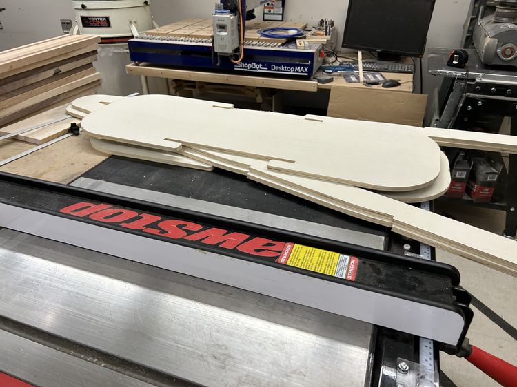
Sanding
I used an automatic sander to smooth out the edges of all of the pieces. For the edges I couldn't reach with the automatic sander, I sanded it by hand. I sanded everything on 80p which was sufficient for preventing splinters for now.
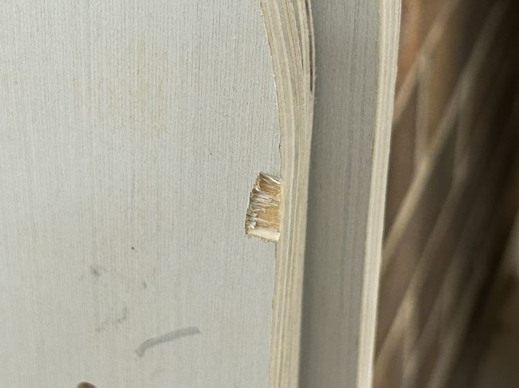
Before sanding I had put one of the shelves on the frames to make sure I had the measurements correct which was tight but functional. There were a couple little chips that occured when trying to remove the shelf, some of which I could sand away but others I couldn't. I also think the fit of the joint will be better slightly easier after sanding all of the pieces.
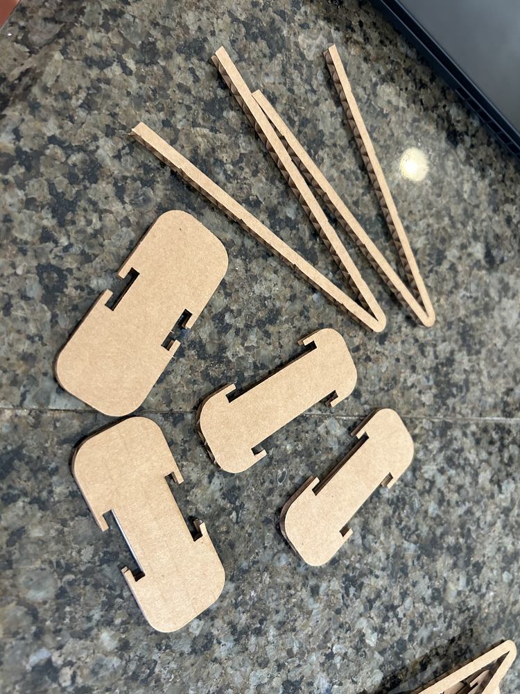
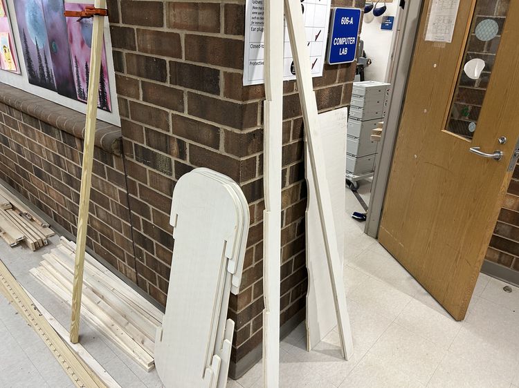
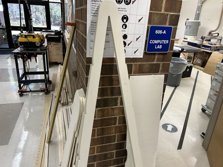
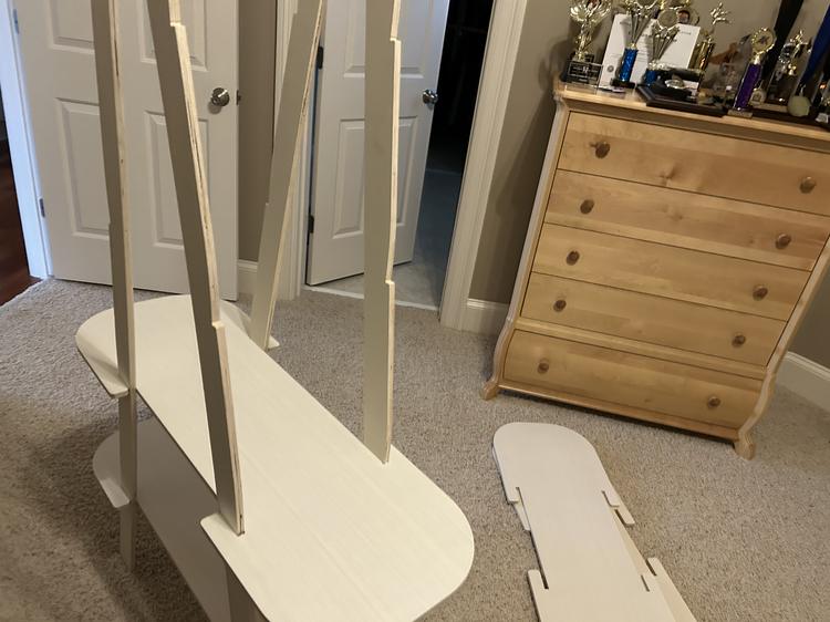
Here are the final pieces!
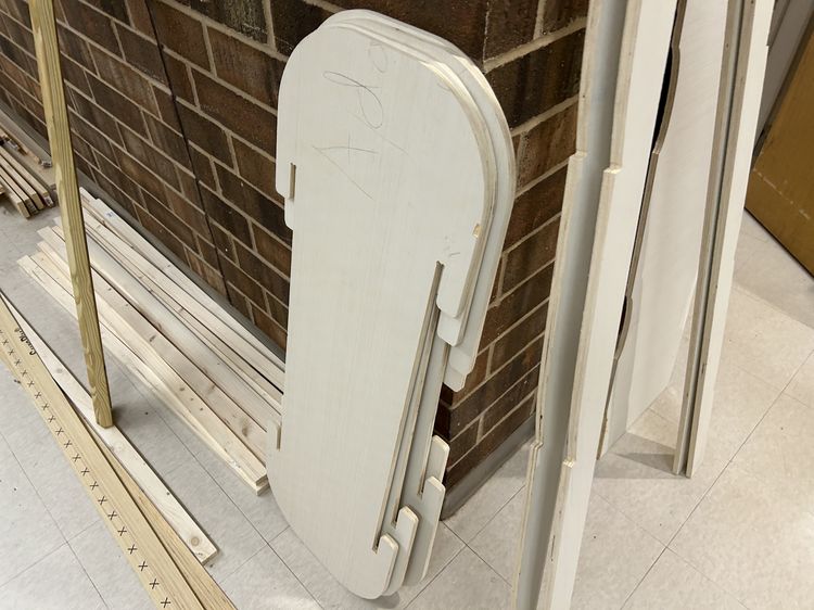
I also erased writing on the shelves from when I chose what board I'd use.
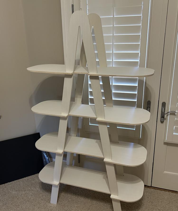
Assembly
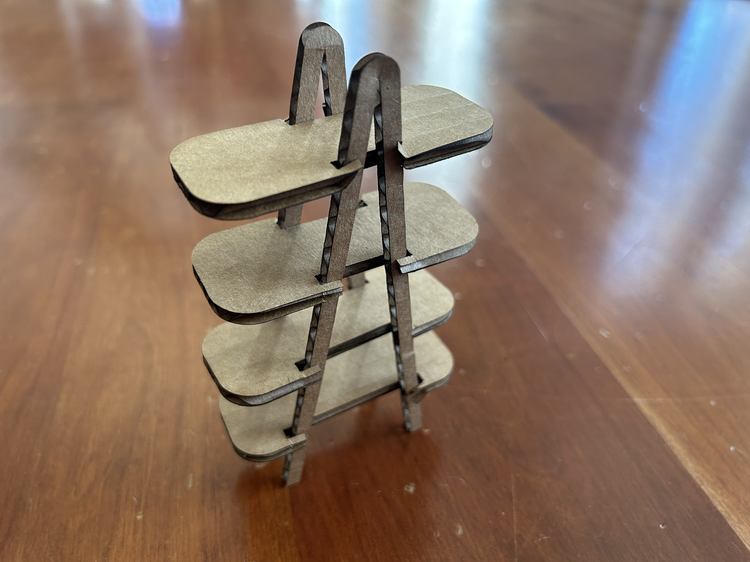
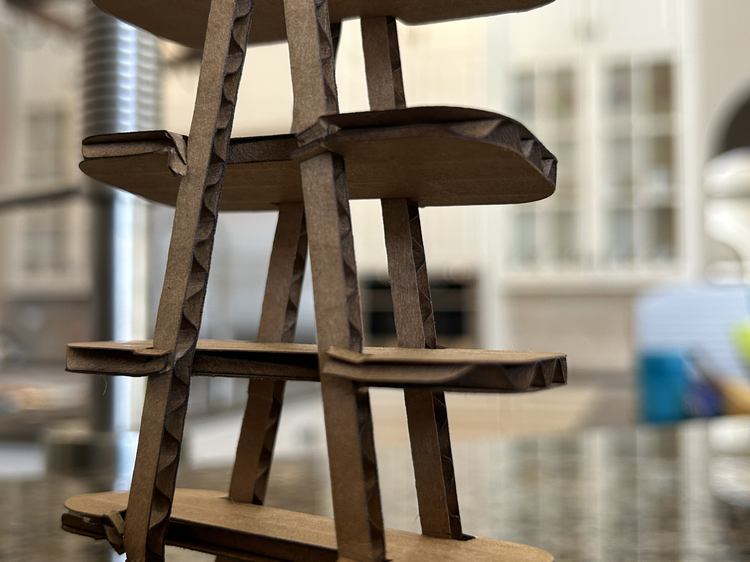
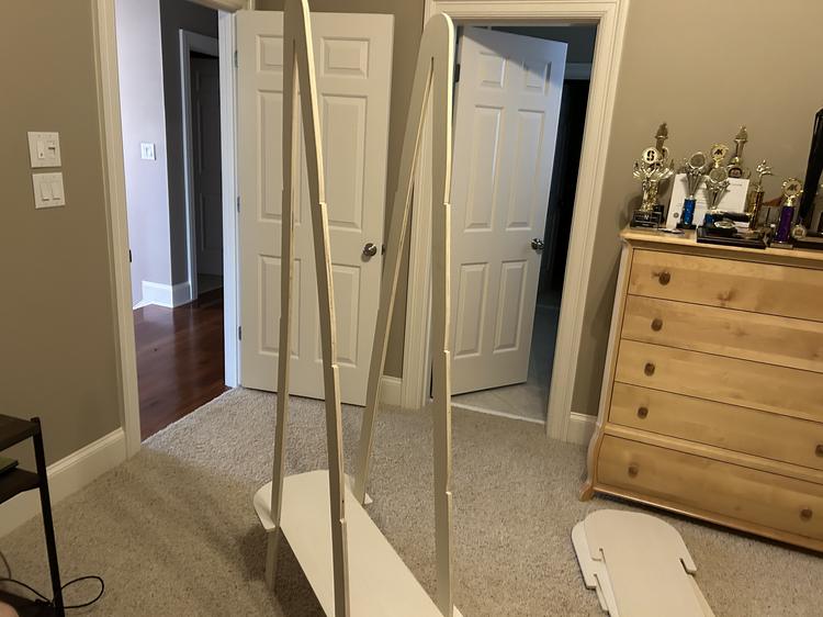
The assembly was fairly smooth. The fit was still very tight after sanding but after carefully but firmly knocking all of the shelves down to their spot I was very happy with the final result. The very top board was the hardest and the plywood started to come apart in multiple spots, possibly because the frames could have been inconsistent and thicker around the top. Anyhow, here is final result!
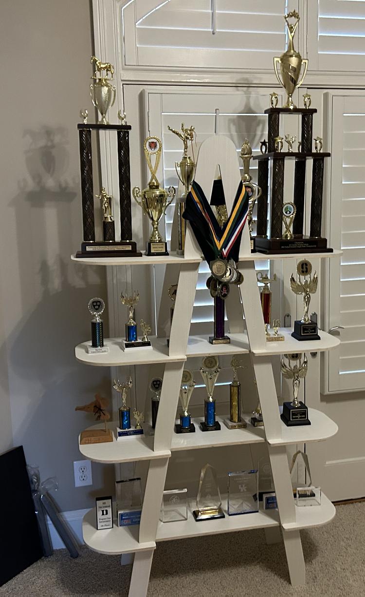
Here's the rendering compared to the final project.