FreeCAD
Download
I downloaded FreeCAD 0.20.2 for Windows from this link.
The Basics
To get started, I completed this beginner's tutorial to learn how to use FreeCAD. I was then presented with the same screen as the tutorial, starting at 3:23.
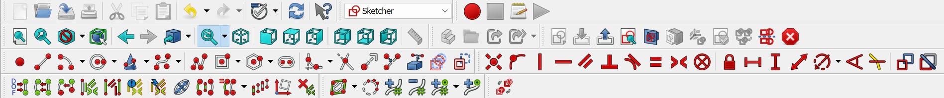
My first impression was that the UI is extremely overwhelming. There are so many workbenches and tools that I can't easily navigate through. For example, this is only the shortcuts for the Sketch workbench. Even so, I do like the ability to easily fit the view to any object in the hierarchy and that there are so many open-source workbenches available.
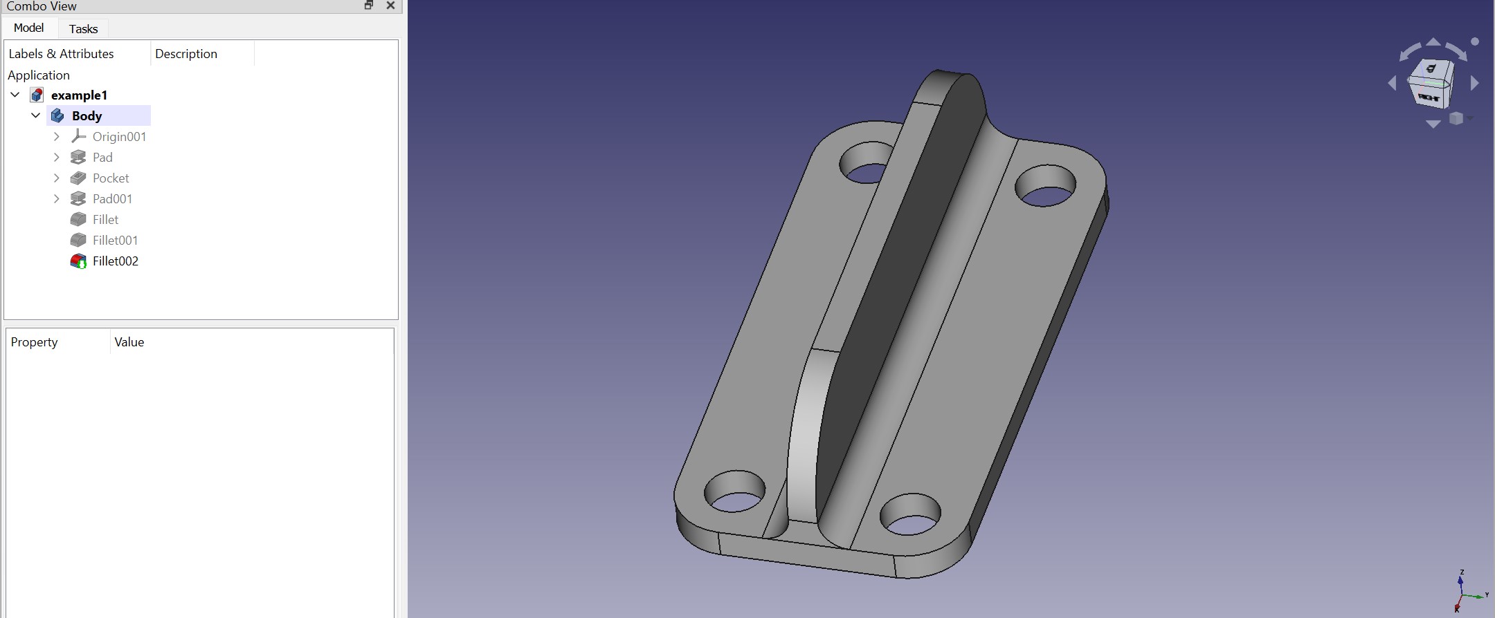
I then followed this tutorial to create a hinge. It all went smoothly and the tutorial was very easy to follow.
Comparing To Fusion 360
Making The Part
Using this video to learn about User Parameters in spreadsheets for parametric design in FreeCAD, I wanted to design the base of the cup holder mechanism that I made in Fusion 360.
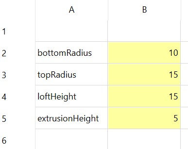
I started by navigating to the Spreadsheet workspace, creating a spreadsheet, and defining user parameters for the bottom radius, top radius, loft height, and extrusion height. I also added an alias for each parameter.
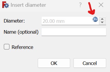
I then went to the Sketch workspace and outlined the profiles for the loft. When I tried to write the formula for the circle diameter, it did not work and simply reverted to the previous value. I realized that I had to first click on the Formula Editor button then type in the variables.
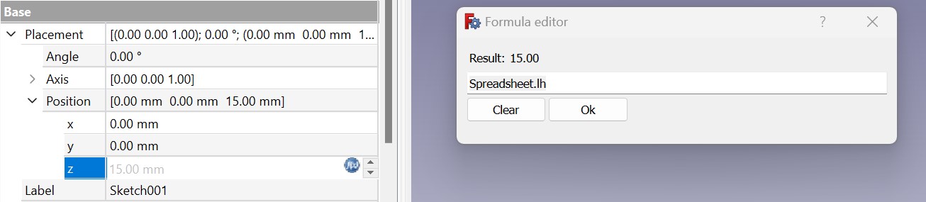
When I created a second sketch, I tried to type in the parameter in the Offset Sketch input field, but this did not work. So instead, I just put in 10mm temporarily then tried to edit the position variable in the inspector for the newly-created sketch. When I clicked the formula editor for the position, I got a Failed to Parse error, so I used the drop down and individual edited the z variable, and this worked!
Then I finished the top sketch.
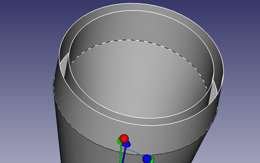
I then moved to the Part Design workspace and tried to create a loft between the sketches, but I was presented with this screen.
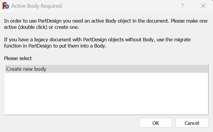
I clicked Create new body, but then was unable to add the sketch profiles! Therefore, dragged the sketches under the empty body the loft command created and tried to add the bodies to the loft again. I pressed OK because the sketches were already added, then I was presented with another screen where I could add the two sketch profiles by pressing them. Then the loft was created, and I pressed OK!
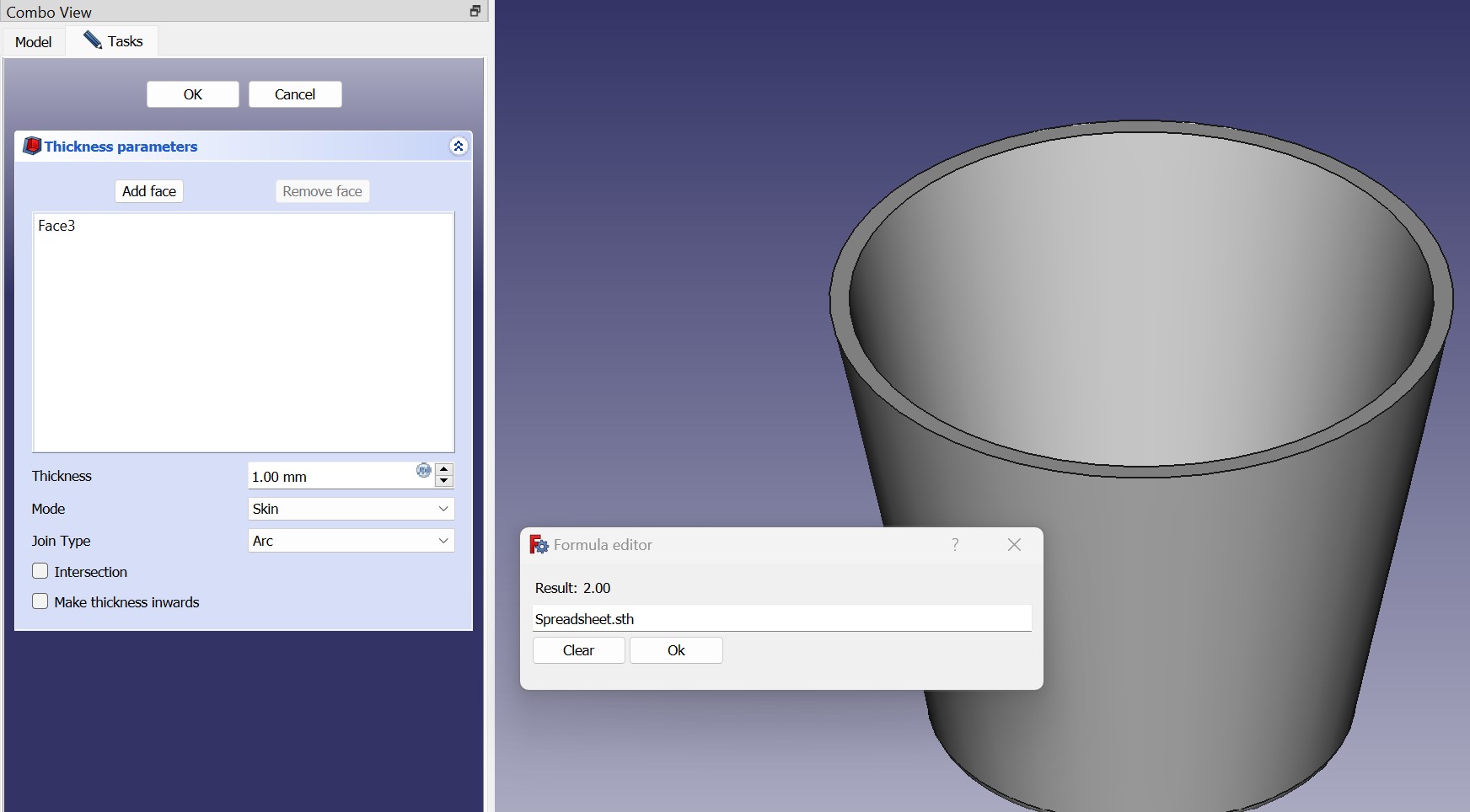
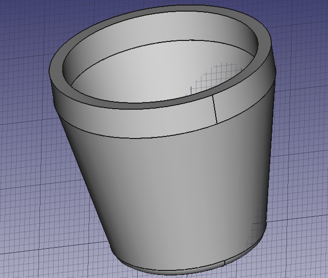
Next, I selected the top face of the loft and activated the Thickness subtractive tool. I created a parameter for the thickness and in entered it in the following screen. My understanding is that the Thickess tool is the same as the Shell tool in Fusion360.
When I tried to pad the top ring of the body, I was unable to add the profile for some reason. I'm not sure why this wasn't an option, and I toggled the different settings, but nothing worked. Therefore, I instead created a sketch along the top plane, projected the geometry into the sketch, moved the sketch under the body, and used that to create the extrusion. The problem was that I recieved an error when trying to project the sketch geometry. Instead, I used the parameters and created equivalent circles on the sketch plane. For some reason, I still wasn't able to select the profile of the sketch.
I realized that I am actually supposed to use the Extrude command in the Part workspace, not the Pad tool for this scenario. Selecting the face with the Extrude command did not work, but when I selected the sketch, I got this strange, but closer, result.
I went back to the Pad tool, but this time checked the Reverse toggle. The pad worked this time, but it extruded in the wrong direction, which led me to believe that I may have created the sketch from the wrong side. So I tried to pad again with the Reverse option selected while also setting the Custom Direction to -1 in the z-axis, but this gave an error that the resulting body wasn't solid.
Finally, this video revealed to me that the Trimex tool in the Draft workspace is really what I was looking for. It allows the extention of a certain face of a body. I created the extrusion then went back into the hierarchy and changed the z variable of the Dir vector to the Extrusion Height parameter that I created. For some reason there is now a grid at a weird angle in the 3D view, but I'm not very concerned about this as it doesn't seem to affect my modeling.
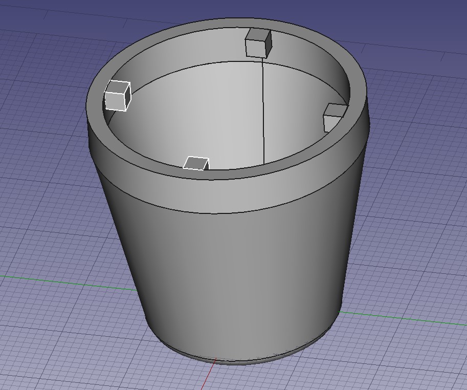
Finally, I needed to create the little knobs for the locking mechanism. I found this tutorial about making sketches on curved surfaces, but this seemed overkill for what I was trying to accomplish. In fusion 360, I simply created a sketch and extruded it downwards to create the knobs, and I did the same thing here.
After creating the sketch, it was extremely difficult to extrude it. I first tried to use the Extrude command in the Part workspace, but it was very difficult to select the sketch profile, and at best I managed to extrude a flat outline of the object. I played around with different settings, but nothing seemed to work.
I then occured to me that I might have a problem with the way in which I created my sketch. I created a line half of the width of the rectangle then created a 2-point rectangle starting at the top of that line. When I went back and deleted the original line, I was able to successfully extrude using the Extrude tool in the Part workspace and checking the Create solid option in the tool dialogue.
After creating one knob, I had to create three more in a circular pattern. This was the most painstaking part of the process. I started off with this website explaining how to create a circular array. I played around with different settings for quite a while but nothing managed to place the knobs with the correct position and rotation. To create a center for the array, I created a sketch and placed a point at the center, but then I for some reason couldn't select that point as the center of the array, so I drew a line out from that point then selected the end point of the line. Then the array was centered around the right place, but the spacing wasn't correct no matter what I tried.
I also tried to use the Polar Pattern tool in the Part Design workspace, placing the extrusion into a new body then trying to make a pattern using that body, but I recieved an error saying that a feature to use in a pattern must be additive or subtractive.
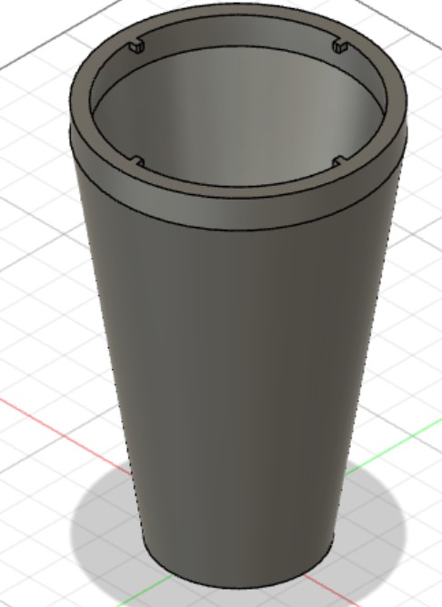
I final copied the square from the original sketch and used the Equal constrain to make sure all of the knobs had the correct dimensions, then extruded them all based off of the same parameter to complete the shape! I'm comfortable with my methods not being perfect since I don't plan to pursue this software in great depth.
Here is the result in Fusion360, for comparison (the parameters are slightly different, but the part design is the same).
Conclusion
Overall, I had a much better experience with Fusion360 then FreeCAD. I recognize that I have bias because I'm more used to Fusion360 and have more experience using it, but my main deciding factors were as follows:
- less intuitive GUI
- overwhelming amount of options
- difficulty in selecting sketch profiles
- challenging to intuitively create simple additive features
- meticulous to navigate active components in the hierarchy