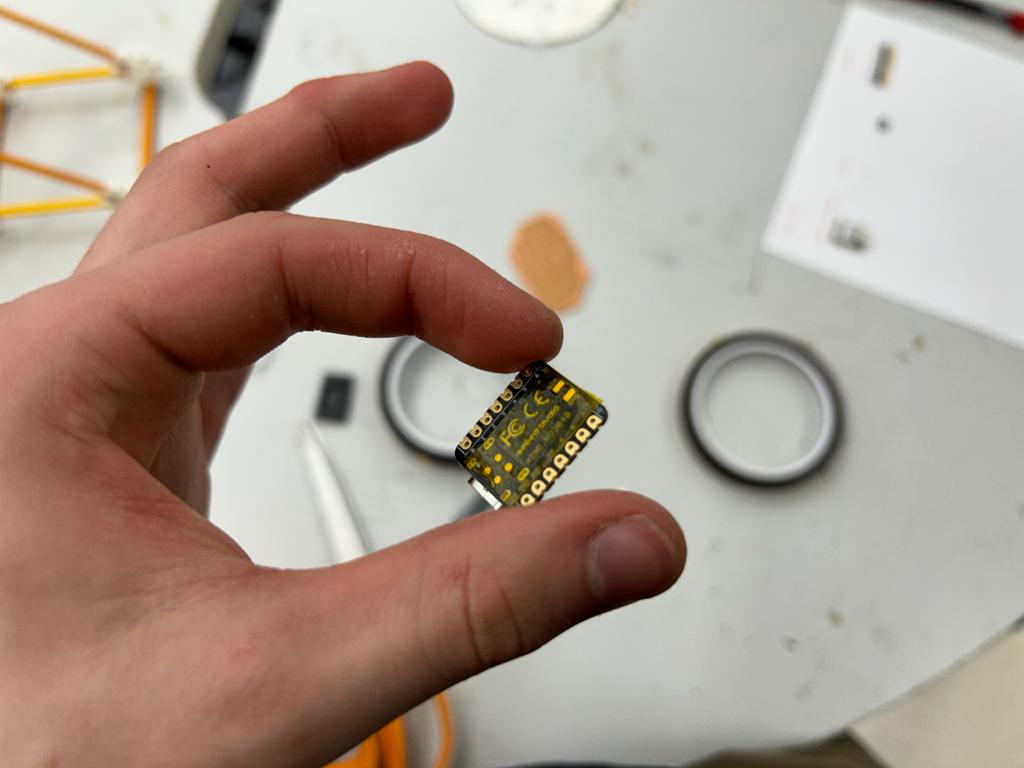
Seeed Studio XIAO RP2040 Development Board
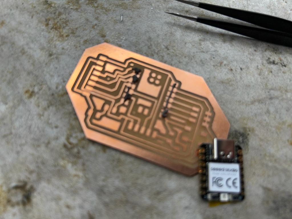
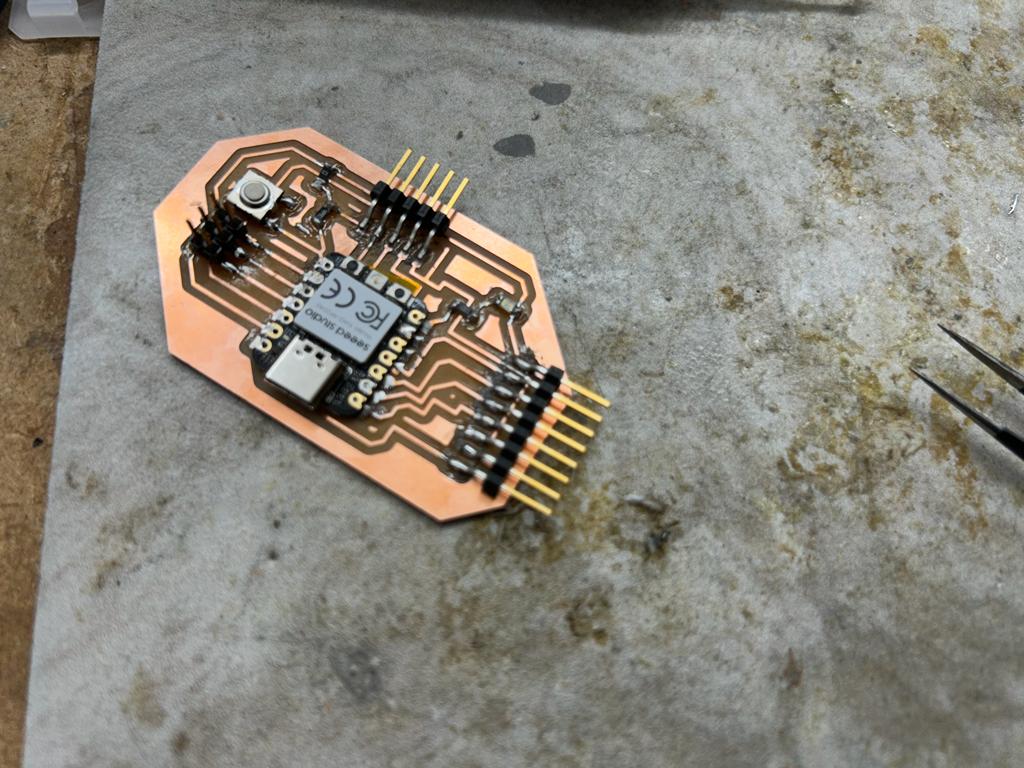
Dr. Taylor had designed and milled development boards for the Seed Studio XIAO RP2040 micocontroller.
The soldering process was fairly smooth, and I didn't encounter any large issues.
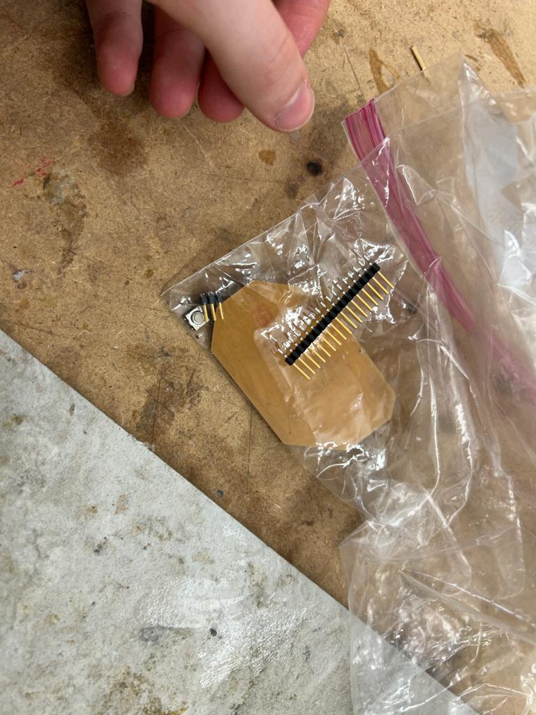
I put 3mm, non-conductive, high-temperatue tape on the back of the microcontroller so that it would stay in place.
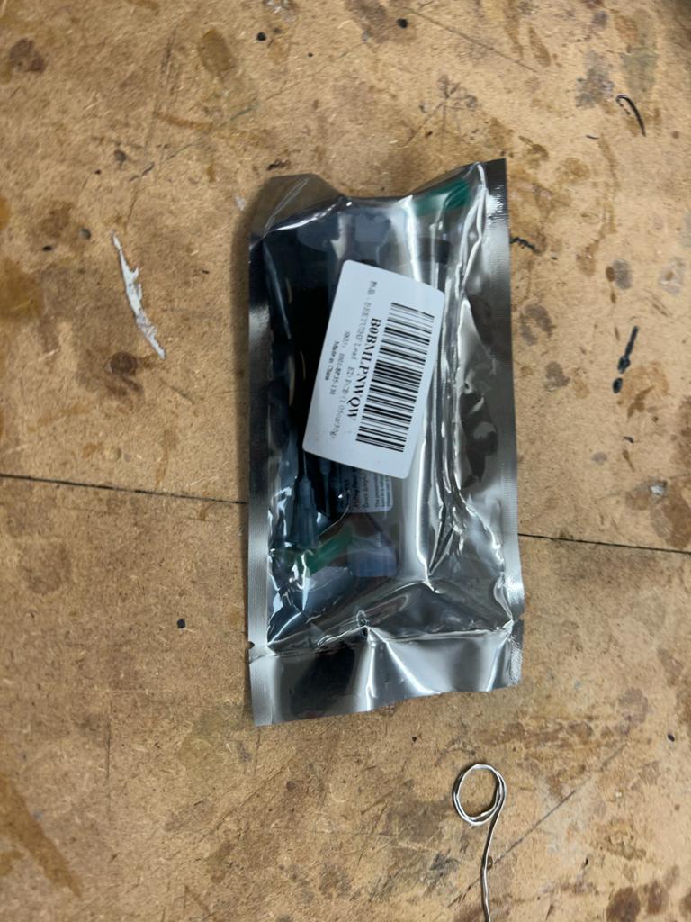
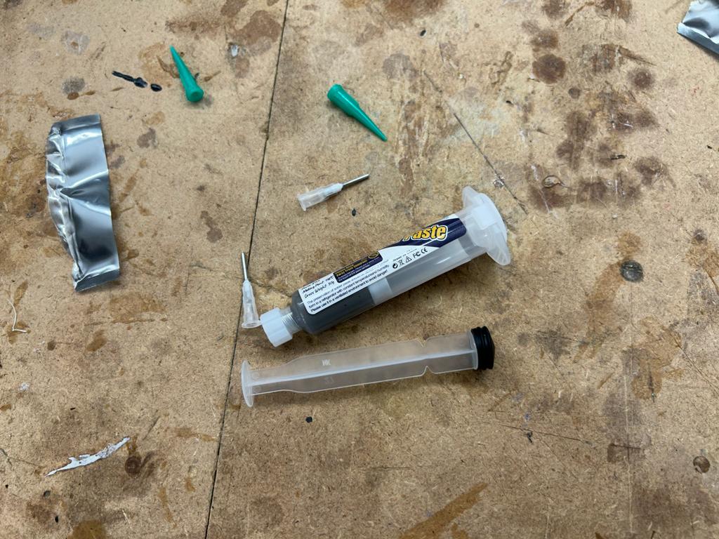
Then I layed down the led-free solder paste.
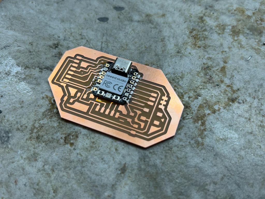

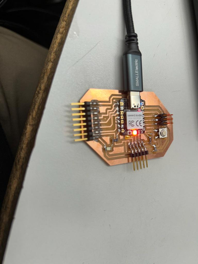
Using a USBC to USB chord I plugged in the microcontroller and it immediately started blinking the on-board LED.
Then I opened the Arduino IDE and selected the board (Tools > Board > Raspberry Pi Pico/RP2040 > Seeed XIAO RP2040). I also selected the port (Tools > Port > COM24).
I found a pinout diagram here and wrote the following code.
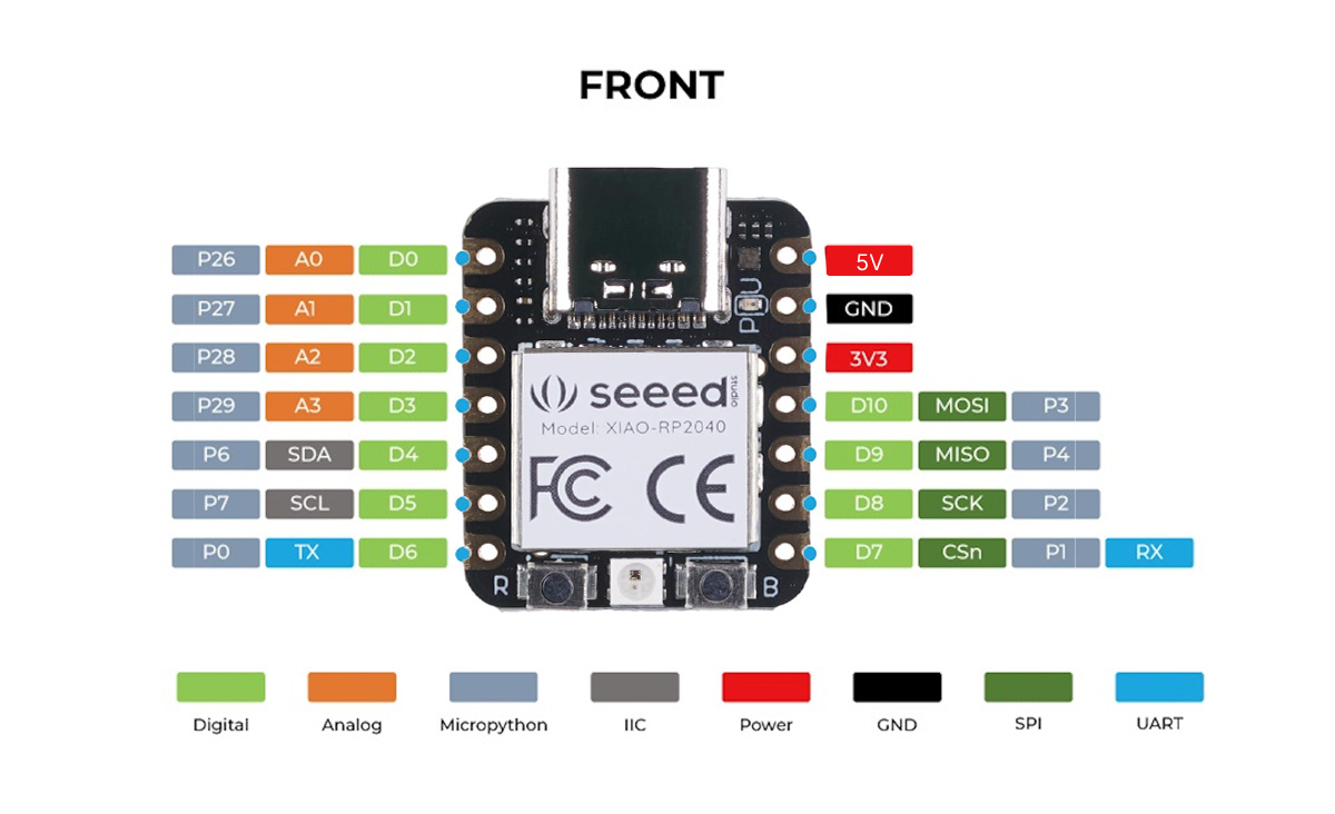

void setup() {
    pinMode(6, OUTPUT);
}

void loop() {
    digitalWrite(6, HIGH);
    delay(1000);
    digitalWrite(6, LOW);
    delay(1000);
}
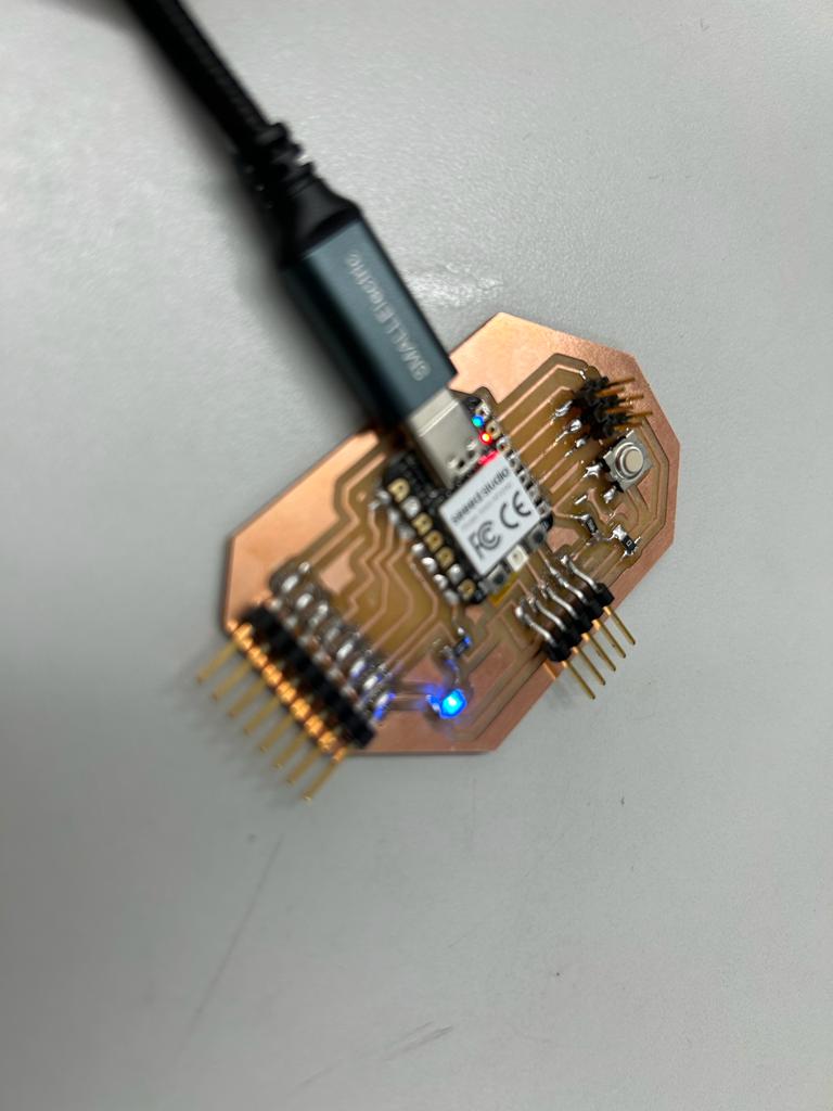
If everything works, it should blink the LED in the development board.
It took forever to upload the sketch and it never stopped loading. I then realized that I was using Arduinio IDE version 1.8.18 so I copied the code to version 2.0.3.
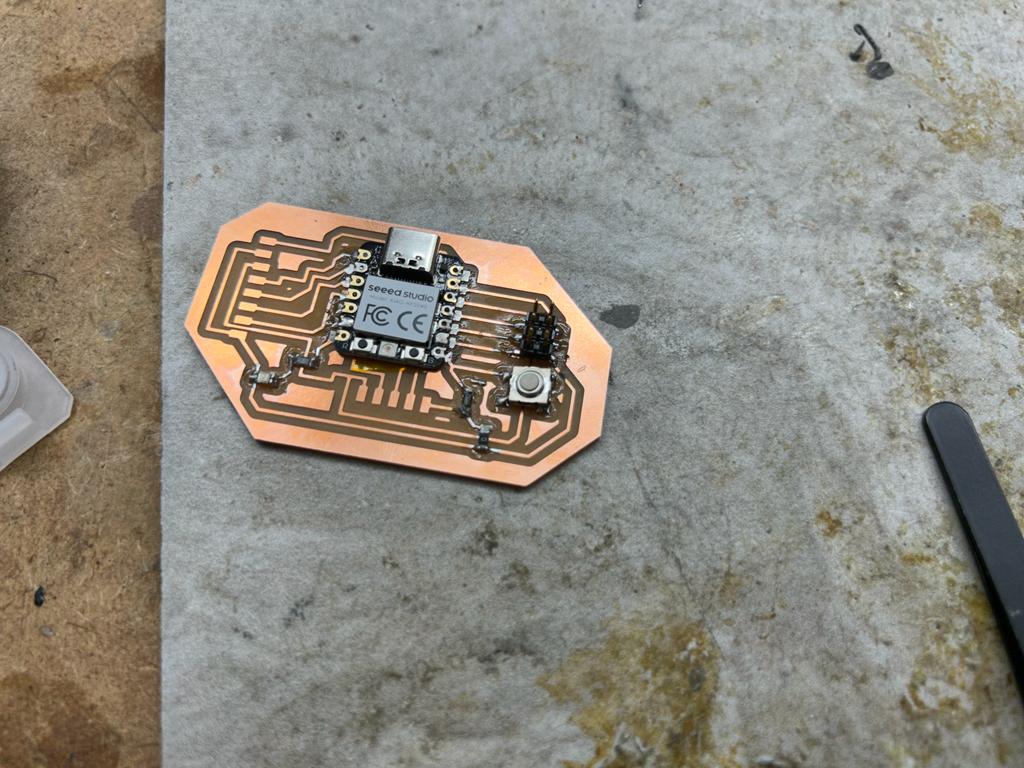
I also remembered that I had to enter bootloader mode, so I pressed the button labeled B as I unplugged and replugged the board. It took a couple tries then wokred because I saw the USB drive popup appear on the computer.
Mr. Dubick recommended applying clear nail polish to the board. I may try this in the future but longevity isn't a high priority for this development board at the mooment.
I remembered that last week Mr. Dubick mentioned needing to upload twice. After restarting the Arduino IDE I tried this and saw an option for the UF2 board under Tools > Board. I selected that and uploaded the sketch.
Now the sketch uploaded, but it didn't work. I tried using the gray numbers in the pinout sheet and switching to pin zero, and this worked, even though I'm not completely sure why, since I'm not using MicroPython.
void setup() {
    pinMode(0, OUTPUT);
}

void loop() {
    digitalWrite(0, HIGH);
    delay(1000);
    digitalWrite(0, LOW);
    delay(1000);
}
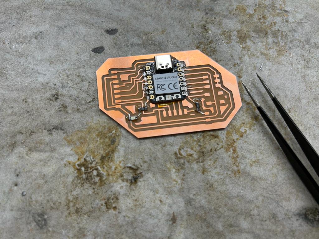
I then grabbed a multimeter and changed the measurement setting to test for continuity. I touched the probes together and heard a beep, ensuring that the machine was working.
I originally thought that I detected some solder bridges with the header pins on the left side of the board, but then I tested someone else's board and didn't get the problem. I then tried again and didn't find any errors. I just realized I was detecting the two connected ground pins and one of the pins that moves behind the other male pins, so when I detected what I thought was a solder bridge, they were supposed to be connected.