Fusion 360
I started off by modeling everything in Fusion 360 to help me better visualize and plan out the individual components that will go into my final project.
Cup Holder Mechanism
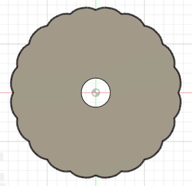
Base Design
I started off by designing the cup holder mechanism. I made the entire design parametric, using User Parameters so that when I actually measure a car I can input those values, and the design will automatically update. I began by making the cup holder itself.
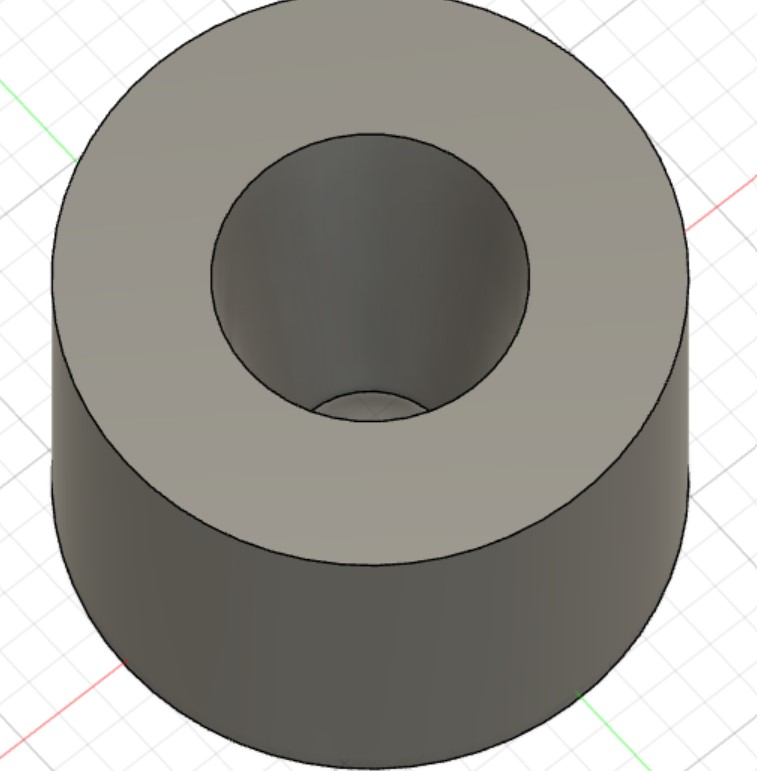
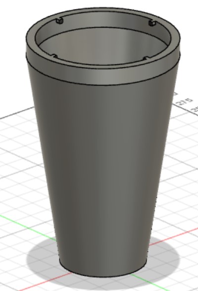
Then, used the Combine tool to subtract the cup holder from a larger body, also using the Offset Faces command with tolerance parameter to make sure the mechanism will definitely fit on the holder. I then extruded the top of the shape upwards (I originally did this because I wanted to use a thread to screw the cap on, but decided against it because the electronics would likely become very twisted and possible disconnect when screwing on the lid). I used the shell comand to make it hollow, and added four bumps that will go into the locking mechanism.
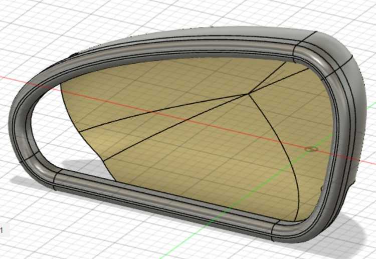
Next, I designed the lid. Using the same tolerance parameter as before, it fits into the case.
I then finished the locking mechanism. I created a square sketch on the underside of the lid, extruded and it upwards. Then I created another sketch on the side that had just been created and used the Sweep command along the circular edge of the lid to complete the shape. I then drew rectangle on the bottom of the newly-created face and used the loft command to create the slant. This would ensure tightening as the lid was put on.
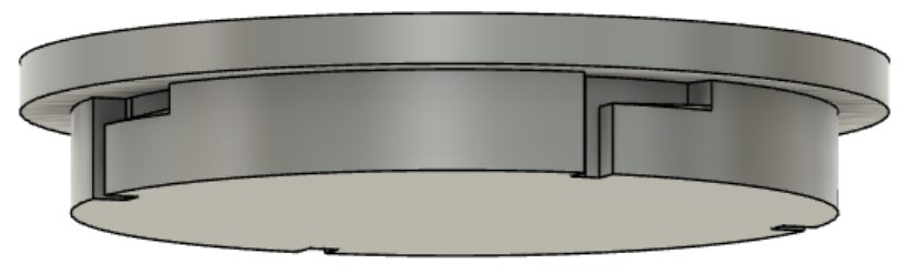
Finally, I created another, large sketch and swept it very shortly backwards to create the divet where the mechanism would lock into place - I also added filled to make sure none of the pieces would get stuck.
I wanted to check whether both sides of the mechanism fit together correctly, so I right-clicked on the outside body, selected Opacity Control and clicked 50%, yet nothing happened. This forum explained to me that I needed to change a setting in my preferences for this to function, and when I changed this, it worked!
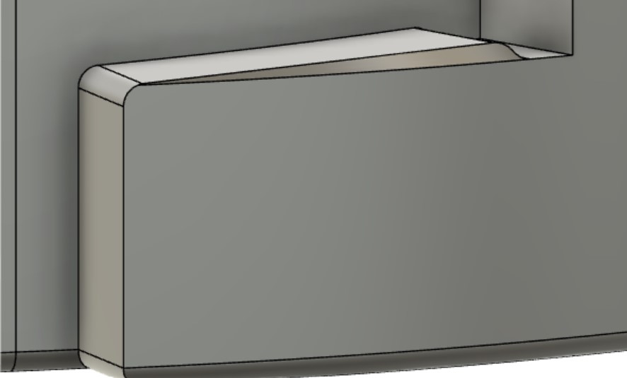
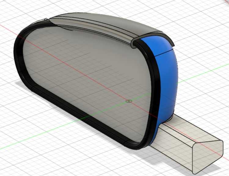
I also added grips using the Circular Pattern and selecting Feature for the type of object. I created a User Parameter for the number of grips and set the angle of the arc for each grip to 360 divided by the number of grips, then set the number in the Circular Pattern to the number of grips, making that aspect of the design fully parametric. I also created a circle in the middle where a button will go.
I had also considered using snap-fits but decided against it for ease of removal when tsting and for durability while driving around.
Button
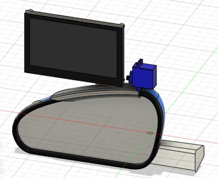
Online I looked for a 3D model of an arcade button and found this one on GrabCAD. To convert the STEP file from GrabCAD to an STL file I could import directly into my file in Fusion 360, I uploaded the STEP file like this, then exported it as an STL. Now that I had it as an STL, I imported into my project successfully. Unfortunately, there were still two problems: the button was much smaller than I wanted and the simple geometry had been replaced by many triangles instead of smooth surfaces.
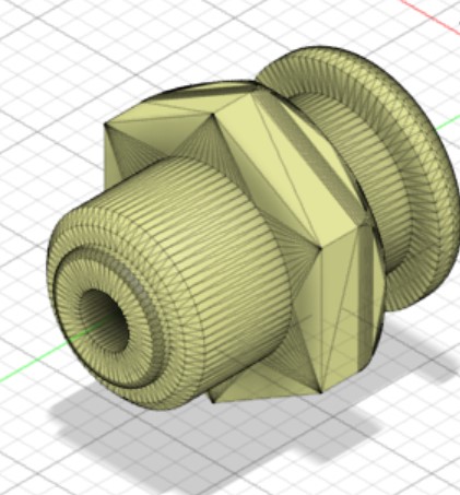
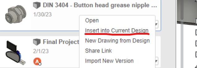
The triangles had been formed because I exported as an STL file which is built of many small triangles. To fix this, I instead had right-click on the newly-created file from the import and select Insert Into Current Design. This preserved the precise geometry and eliminated the need to export as an STL then import as a mesh.
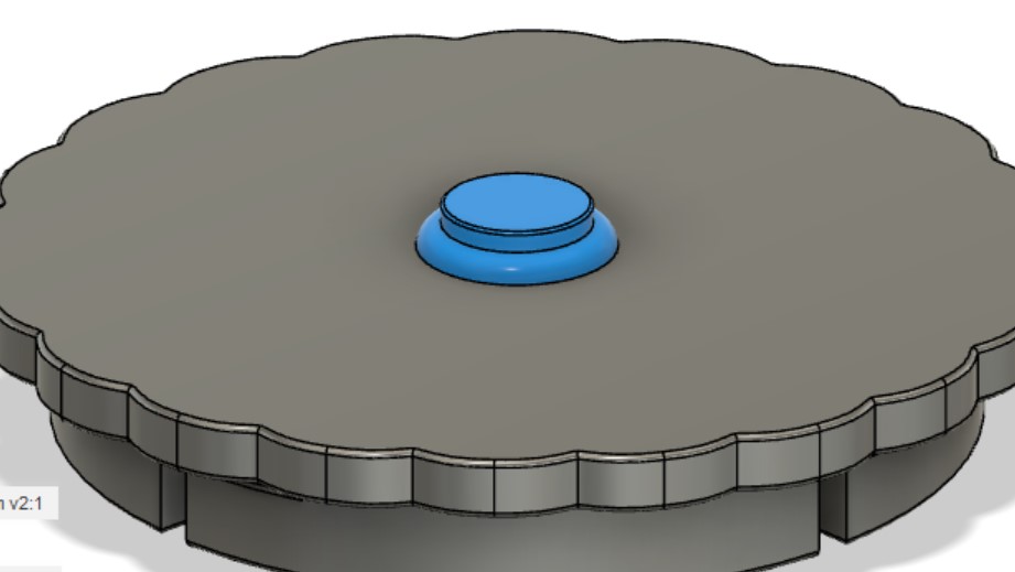
I visualized this button to look more like an arcade machine button. Online, I looked up standard sizes for arcade buttons, and decided I'd use a 30mm button in my design. I wasn't sure where the 30mm was talking about the radius or diameter of the button or which part of the button it was talking about. I found this technical drawing online, and it revealed to me that I needed to make a 30mm diameter hole in the lid for the button to fit. Avoiding my mistakes from the last import, this one worked successfully. I added a rigid joint to move the model into place and it fit nicely into the 30mm hole I created in the lid.
Here's a picture of the cup holder mechanism finished, animated with a slider joint, and connected the lid and button sub-components using a rigit as-built joint. When displaying the animation, this forum taught me that I need to make sure to click Animate Joint Relationships not just Animate Joint so that the rigid join would still apply and all necessary components would be moved during the animation.
Screen Display On Mirror
The next step was to create the attachment mechanism for the screen to the car. I wanted to find a CAD model of a mirror like this, but this website was giving me trouble when I tried to download the model. I eventually found this model and imported it into Fusion 360.
I tried first to create a solid block around the top of the mirror then combine the bodies subtractively so that I'd be left with 2D cross-section of the mirror that I could sweep around the mirror to create a piece that fits on nicely. I was able to create a mold of part of the mirror, but sweeping it around and extending it at an angle were very difficult and didn't produce satisfactory results. So, I chose a different approach: I used the Offset Face command to try to create a slightly larger version of the entire mirror. When I ran this command, the body was not fully defined and parts of the faces were yellow.
This reminded me of this Product Design Online tutorial about the Patch workspace in an older version of Fusion 360. Unfortunately, the Patch workspace no longer exists in Fusion 360, but when I searched the Patch command in the tools shorcut box, it appeared and I was able to repair the body. This page explained that I needed to use the Stitch command to combine the patches with the original body, but I got an error when I attempted this. This source taught me that some of my patches were backwards, and I needed to use the Reverse Normal command to resolve the problem, then stitch again. This worked!
I then split the body using construction planes and had a working grip on the top of the mirror.
For now, since I hadn't decided on what display I was going to use, I found this CAD model of a display and imported into Fusion 360. I also found this servo motor and imported it, as well.
STOP!
Before I got any further, I majorly rethought this portion of my project. I had spoken to another law enforcement official (see this page for details)) and decided that I wanted to instead have a display through the back window of a car.
I also decided to use an e-ink display that would be easily visible for an officer during the day, and I'll add backlights so that it's visible at night. After trying several different displays, I found that I liked this one the best. I also found this instructions page for how to set up the display with an Arduino or Raspberry Pi.
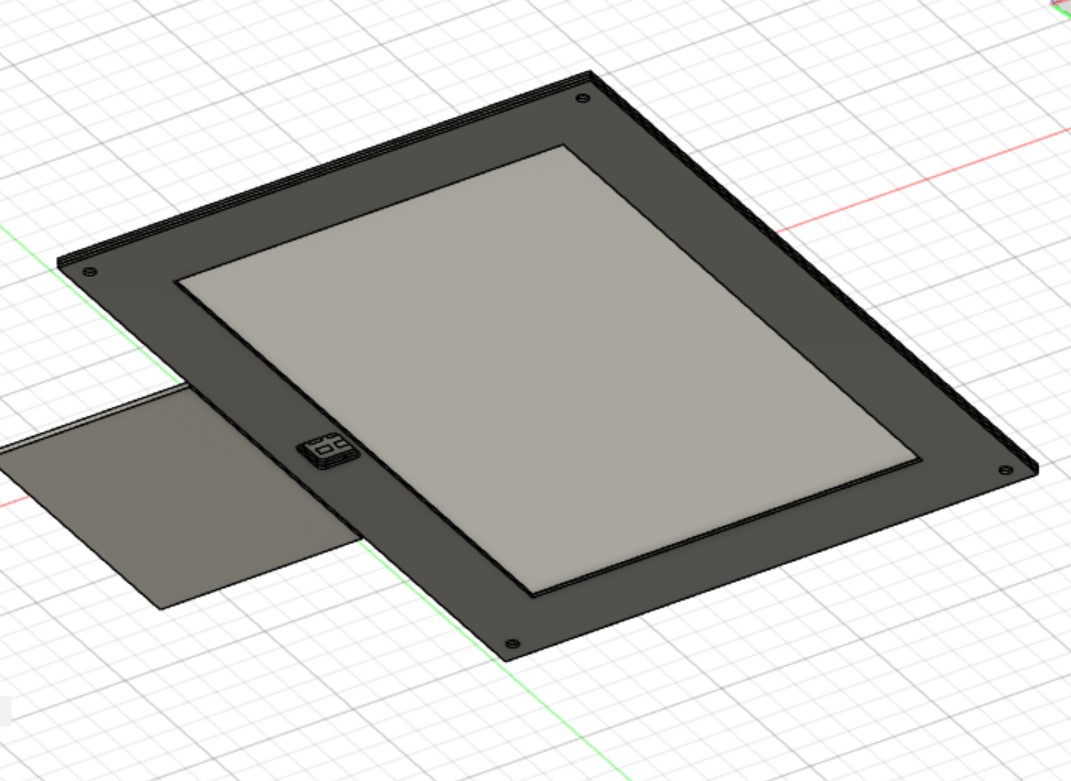
I imported the servo-driven hinge model into Fusion (I recognize that I will likely later have to adapt the model for a more powerful motor) and tried to edit the plate subcomponent, but none of my changes were working. I realized that I had to right-click on the imported component and selected Break Link to delink the imported component from the uploaded file. Then I was able to adapt the model to match my design in Cuttle.
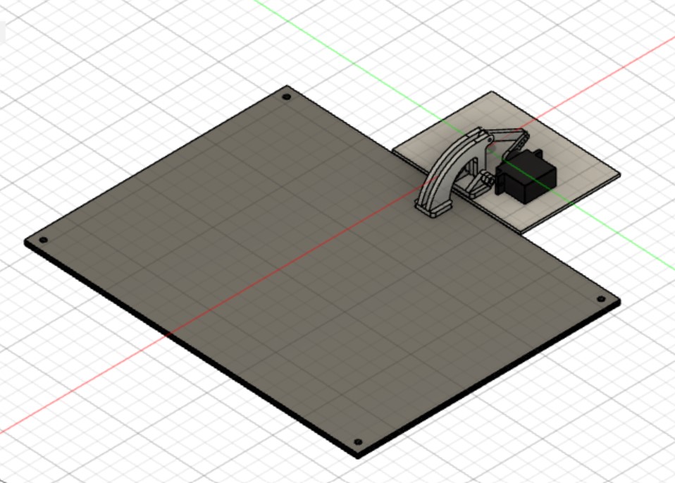
I also tried to import a manufacturer part for an M4x4 Hex Bolt through Fusion360, which brought me to a different webpage. I found the part I wanted, but I wasn't able to import the model. This wasn't very important for my design since I already decided on what screws and nuts I'll use as well as the measurements.