Milling The PCB
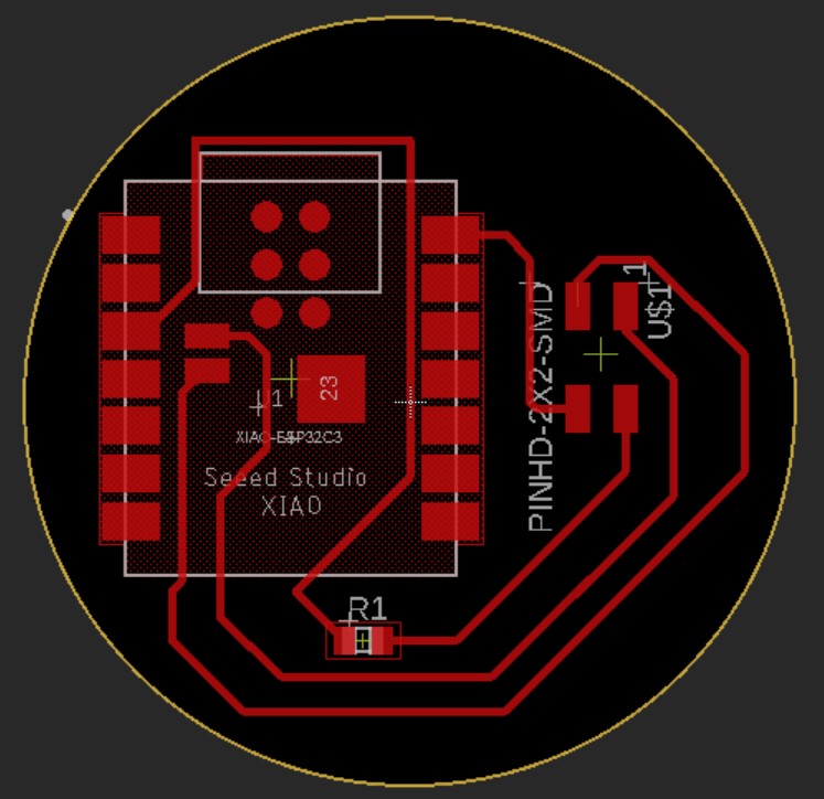
Ryan Kim taught me that for the milling machines in our lab it's best to export using the Export Gerber, NC Drill, Assembly and Drawing Outputs button under the Manufacturing menu in the Layout Editor. I exported this ZIP file and uploaded it to Google Drive.
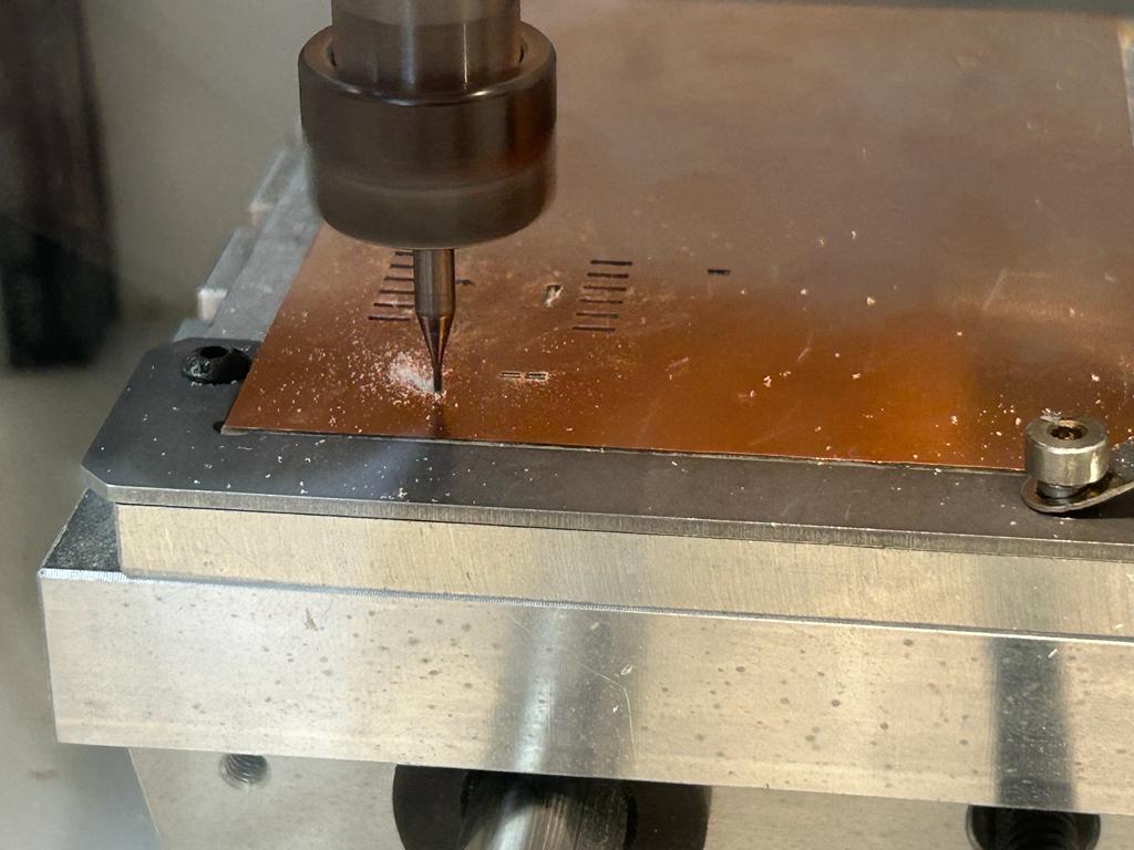
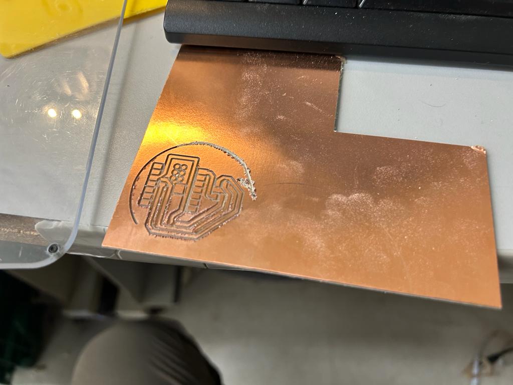
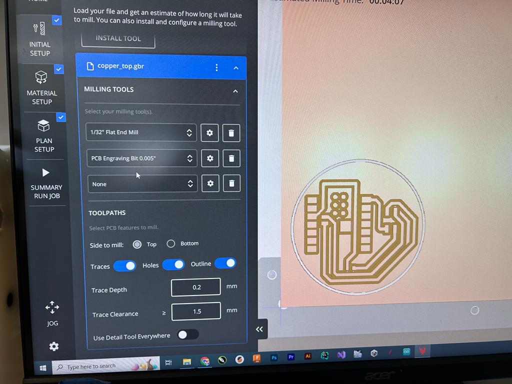
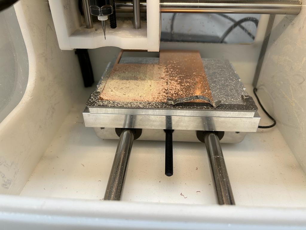
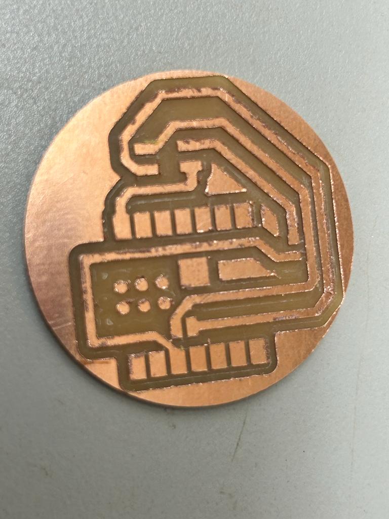
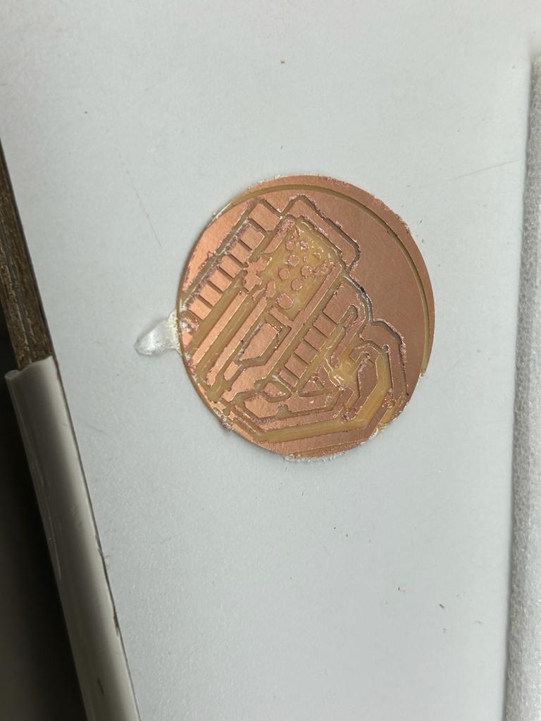
I opened the Bantam Tools software on a copmuter connected to a milling machine and downloaded the ZIP file from Google Drive. I unzipped the file then opened the copper_top.gbr file. I then changed the outline to profile.gbr and moved on to the next several settings. I then realized that my traces were too small even with a very precise bit, so I opened EagleCAD and typed change width 16 in the command box then clicked on all of the traces. This increased their width to 16mil (1mil = 0.001in). I then repeated the exporting process. I added the 1/64" End Mill and 0.005" Engraving Bit bits in the software and changed the Trace Clearance to > 1.5m then left the next two screens of settings with the default values (I only needed the really small engraving bit because of an accidentaly trace I never deleted - I removed this in the next iteration of the design). I then put three pieces of Nitto Tape across the back of the copper and placed it on the material bed. When I selected MILL ALL I selected OK in the popup and changed the bit to whatever bit the machine requested. When it prompted me to ensure that the bit was above a clear part of the bed, I did so then it ran a touch-off test. The entire milling process when smoothly. At the end I accepted the prompts to walk through the clearning process where I vaccumed the inside of the machine as the tool moved to different places so that I could vaccum everywhere. I used the scraper to remove the board and the result looked great!
Soldering
Before soldering I washed the board in soap and water. Afterwards, the soldering process was very smooth. I used solder paste and soldered the components from smallest to largest. I used the syringe to apply a small dab of paste below each connection, used tweezers to place the component, and held the tip of my soldering iron to one connection of the component. After I made sure the position was exactly correct and one joint was secured, I held the tip of the iron to the other parts of the component until it was fully soldered. I made sure to even hold the piece in place with tweezers when I had already soldered one joint because, especially for smaller components, I noticed that the other connections sometimes heated up and liquified, as well.
The only place where I had trouble was with the resistor - it turns out that the R0603 resistor was not the right size and to small, but for the time being, I simply rotated the resistor slightly and made a larger piece of solder that reaches slightly past the solder pad onto the copper trace. This worked fine.
Testing the Board
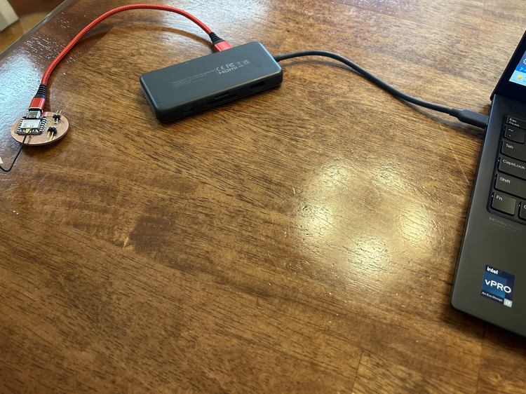
I attached the antenna that came with the ESP32-C3 microcontroller. I then plugged it into my computer via USBC → USB → USBC.
Then unplugged board and held down bootloader (B) button as I plugged it in again.
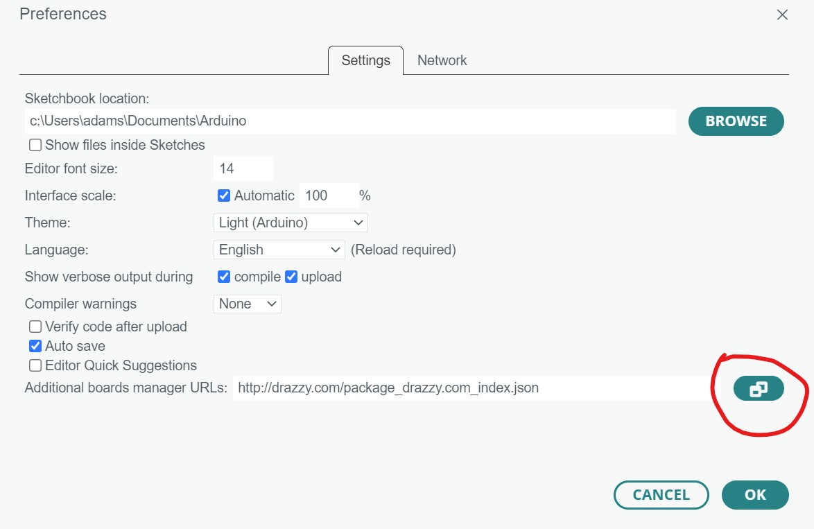
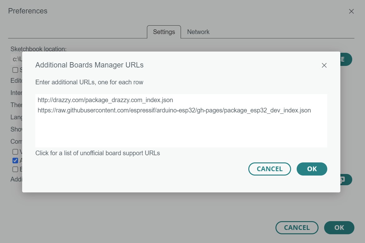
Following this tutorial I opened File > Preferences..., pressed on the icon next to the Additional boards manager URLs: input field, and copied the following URL on a new row.
https://raw.githubusercontent.com/espressif/arduino-esp32/gh-pages/package_esp32_dev_index.json
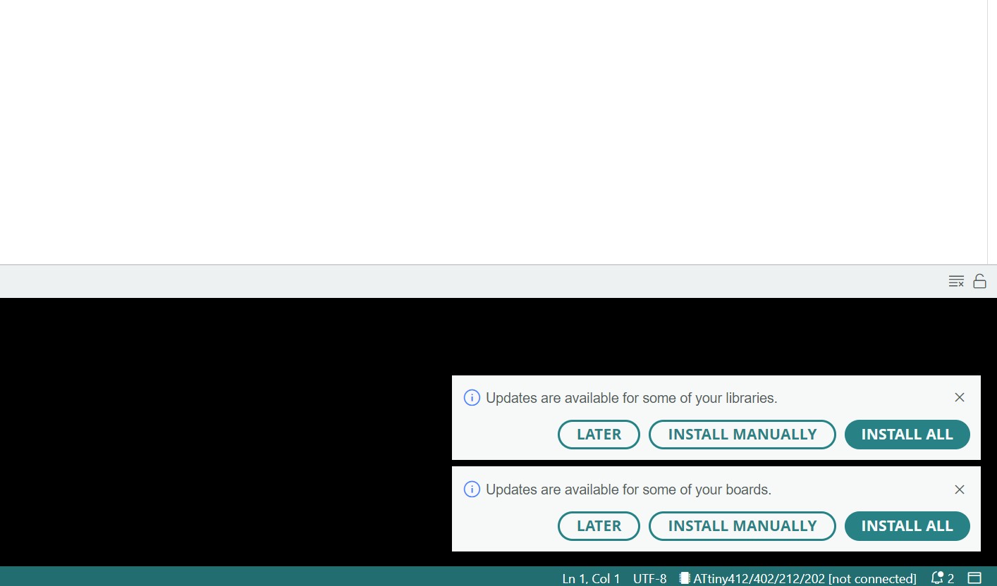
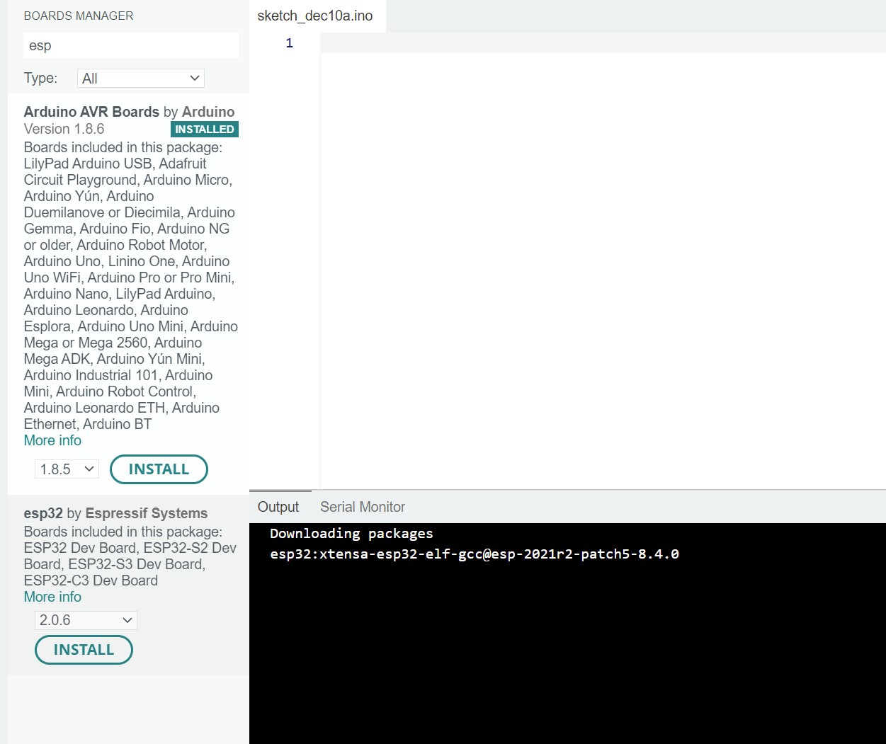
But I didn't see it, so I opened the Tools > Board > Boards Manager... and typed esp32 but I still didn't see anything. I tried flipping the order of the URLs in Preferences but this didn't help.
I saw options to update boards to I clicked INSTALL ALL but this didn't help either.
Finally I tried to restart my whole computer instead of just closing and reopening the Arduino IDE.
This still didn't work! I eventually found this forum which revealed that there is a bug in Arduino IDE 2.0.0 and above where you cannot add mulitple URLs. So I tried deleting the original one I had in there from Week 4 and then it worked once I restarted the IDE! I then installed the library.
I wrote the following program to test my board.
void setup() {
  pinMode(1, INPUT);
  Serial.begin(9600);
}

void loop() {
  if (digitalRead(1) == HIGH) {
    Serial.println("YAYYYYYY!!!!!! :):):)");
  }
}
But when I uploaded I recieved an error that I forgot to select a port.
Failed uploading: no upload port provided
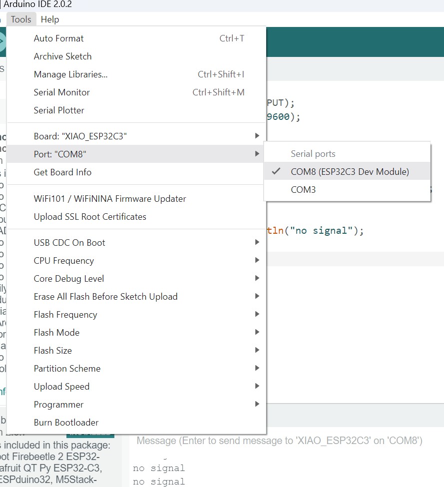
I selected the port COM8 (LOLIN S3) then tried to upload again.
As soon as I connected the button and pressed it a warning in the serial monitor popup up which said I had no port selected, and I checked the port and the parenthetical next to COM8 changed to something else which I didn't write down. Repeated the process and it changed again to COM8 (TAMC Termod S3). This is very strange!
I also tried changing the code to the following, and when I saw no output, realized that communicaiton with the board wasn't working correctly.
void setup() {
  pinMode(1, INPUT);
  Serial.begin(9600);
}

void loop() {
  if (digitalRead(1) == HIGH) {
    Serial.println("YAYYYYYY!!!!!! :):):)");
  }
  else {
    Serial.println("no signal");
  }
}
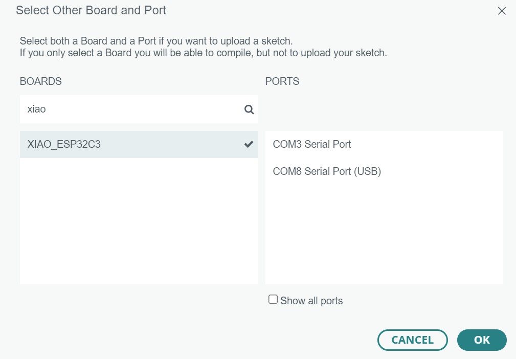
I realized that I never added a resistor when connecting 5v to the input pin, causing the board to turn off. To make sure I was correct I grabbed a resistor. I also realized from this article that hooking up the power and ground to the 5V and GND wouldn't work (I don't think I need to solder those connections). That source also revealed to me that I was using the incorrect board in Arduino IDE.
Only now was I seeing serial outputs of no signal.
I tried changing the pin to 2 then tried all of the pins until the most upper-left one worked!!!
I then tried it with the button and it was successful!
I also learned that I never needed a pulldown resistor since one is already built into the microcontroller.
Redesigning The Board
I set the new resistor to one larger than R0603, R0805.
Failed Again
After milling the board out and soldering it, it worked inconsistently until it eventually was stuck in the input pin was always recieved a HIGH input. My soldering was slightly crooked, and it sometimes worked when I pressed against it trying to rotate it correctly, but I tried unsoldering and moving it, which was not a success.
Redesigining The Board Again
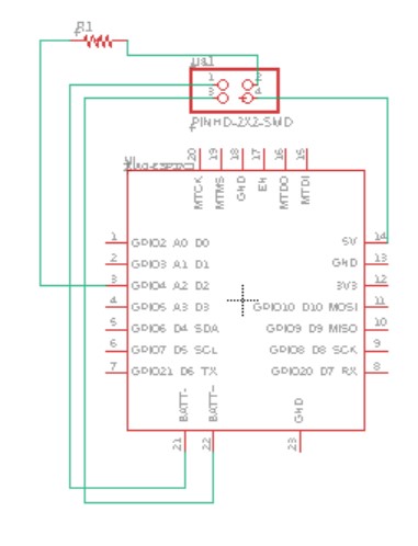
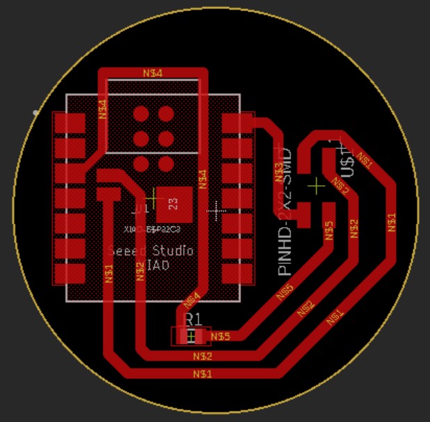
I redesigned all the traces to be thicker, 40mil except on the left side of the microcontroller which only fit 30mil. I set the DRC pad-to-pad and wire-to-pad minimum clearance as 16mil and moved pieces accordingly.
Milling The Board Again
I milled three times following the same steps and the board only worked the second time.
Before starting I used tweezers and my thumbnail to clean gunk out of the bit, as Mr. Budzichowski advised.
The first time I didn't vaccum the material bed before sticking down the nitto tape so the adhesive stuck to the particles instead of the machine bed and the copper moved right at the end of the edge cuts, ruining the whole cut.
The second time worked fine, although the z-probe for material thickness wasn't working, so I simply left the default value from the last milling (I think ~1.67in) and it worked. I also used a PCB Engraving Bit instead of a 1/64" End Mill. I wasn't sure whether to select a 0.005" or 0.003" bit in Bantam and also didn't know whether the bit I had was 30 deg or 80 deg, so I searched images of both and decided to go with the 0.005". Also, this shouldn't have changed the depth, so it's only a matter of the width of the tool, but I know my design works with a 1/64" bit, so either will work fine. Either way, the conservative estimate has less room for error in case there's a small detail it tries to mill and thinks the tool is capable of. After milling the board, then deburred it.


The third time I'm not completely sure what went wrong, but I'm fairly sure the board moved slightly and wasn't stuck down firmly enough.
I notcied one area where two traces weren't completely separated where they shold have been - this was probably why first one iteration didn't work. I used metal scraper to make sure there wasn't a bridge.

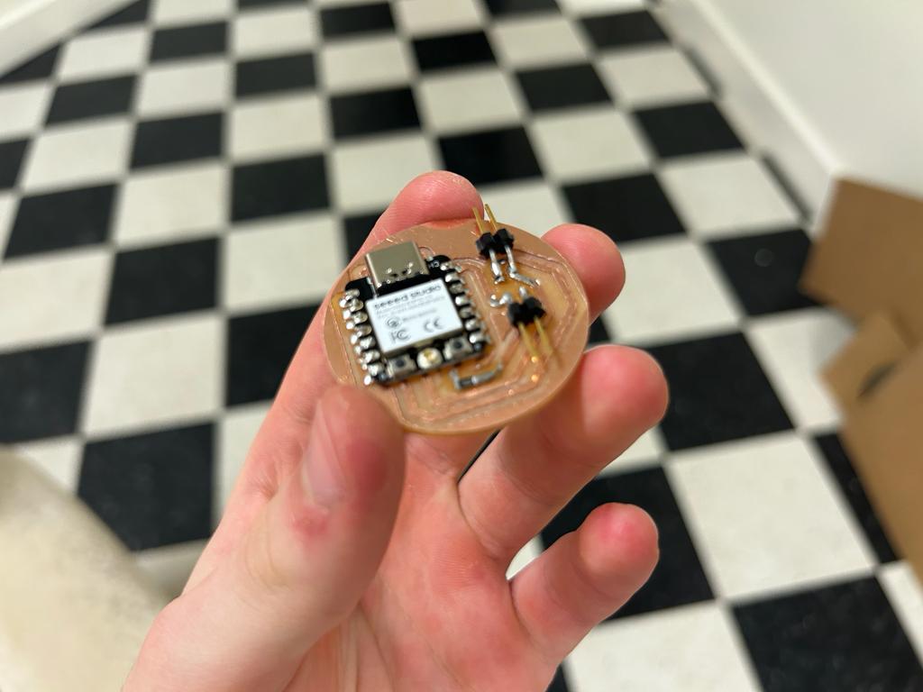
I then soldered this board. I was very very careful to make sure the microcontroller was aligned exactly vertically and evenly. I soldered one corner then held the iron down as I used tweezer to exactly position it until I was satistfied. I realized that I had forgotten to wash the board with soap and water before soldering, but I remembered this before the microcontroller, so I washed and dryed the board before the final soldering step.
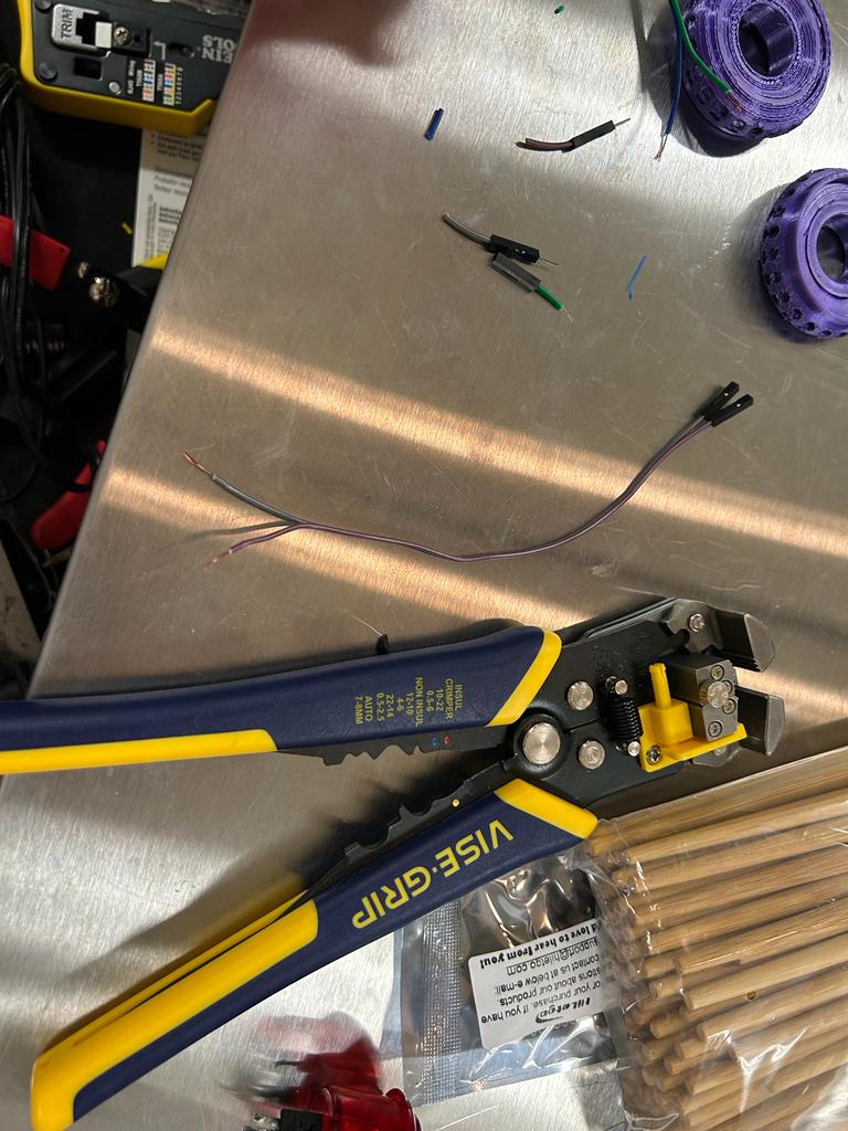
My plan was then to take two female jumper wires and use a wire stripper to cut and strip one end. I would then soldered wire to each of the prongs on the button.
The first time I stripped a male-to-female jumper I realized I cut the wrong end! After getting new wires this worked.
I had two buttons for testing and one of them already had some solder on them from someone who tested something before I took the button. When I tried to remove this solder I couldn't, and for some reason, even when I added more solder and touched the wire to the prong, I couldn't get the solder to harden when the wire was touching the prong. I tried this for too long and the plastic started to melt, making the prongs moveable.
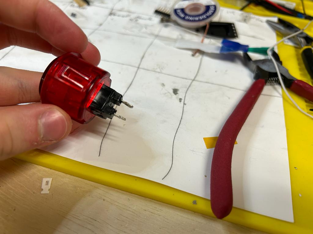
I then tried with the second button, stripped different wires longer, and twisted them around the now-accessable holes in the prongs before soldering. This worked far better.
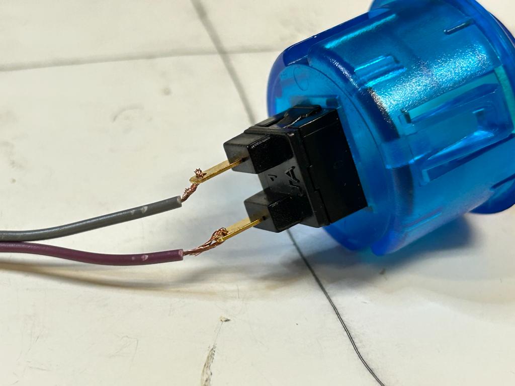
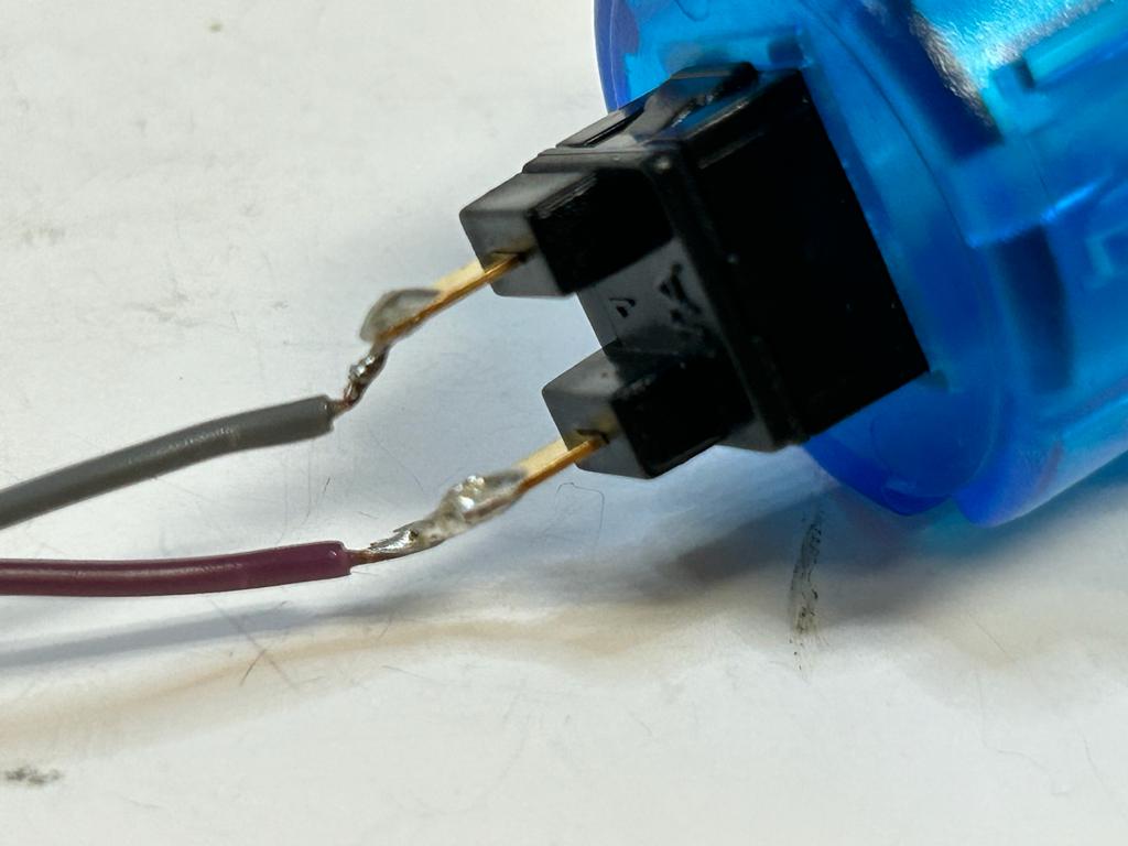
I also made sure to solder the part of the wire sticking off of the button so that they don't move and accidentally touch.
When I plugged this in and uploaded the code, holding down the bootloader when I plugged it in, everything worked, but I saw no output. I unplgged and replugged the board then selected the board and saw output, and it worked!
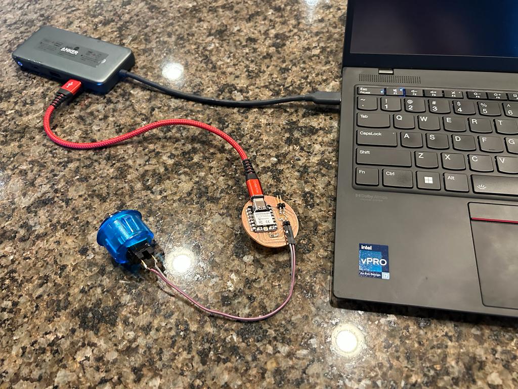
I also noticed that it works when I touch my fingers to the wires instead of pressing the button, but this shouldn't be an issue once the button is inside its enclosing.
I still haven't tested an external power supply, but plan to do this in the future.
Confirming Success
Finally, just to make sure I didn't need a pulldown resistor, I asked ChatGPT 4.0 who revealed that I had a typo in my code and how I should have adapted my code to utilize the built-in pulldown reistor.
Prompt
i designed a board for a xiao seeed esp32-c3 and I have a two-prong button connecting 5v to an input pin with a resistor, but I don't have a pulldown resistor beause I thought it was built into the microcontroller. iwll it still work?
void setup() {
  pinMode(1, INPUT);
  Serial.begin(9600);
}

void loop() {
  if (digitalRead(2) == HIGH) {
    Serial.println("YAYYYYYY!!!!!! :):):)");
  }
  else {
    Serial.println("no signal");
  }
}
(The prompt code wasn't in a code block - it was simply copied as normal text and pasted below the explanation of my request).
Response
The ESP32-C3 microcontroller does have internal pull-up and pull-down resistors, but in your code, you have not enabled the internal pull-down resistor for the input pin. You should modify your setup function to enable the internal pull-down resistor as follows:
void setup() {
  pinMode(1, INPUT_PULLDOWN);
  Serial.begin(9600);
}
Additionally, in your code, you've set the input pin to be pin 1 in the setup function, but in the loop function, you are checking the state of pin 2. Make sure to use the correct pin number consistently throughout your code.

Here's the corrected code:
void setup() {
  pinMode(1, INPUT_PULLDOWN);
  Serial.begin(9600);
}

void loop() {
  if (digitalRead(1) == HIGH) {
    Serial.println("YAYYYYYY!!!!!! :):):)");
  }
  else {
    Serial.println("no signal");
  }
}
Now, with the internal pull-down resistor enabled and the correct pin number used consistently, your code should work as expected.
With this knowledge, here is my final program (I believe my code worked previous when I had the wrong pin in the pinMode function because the default state for all pins is INPUT).
void setup() {
  pinMode(2, INPUT_PULLDOWN);
  Serial.begin(9600);
}

void loop() {
  if (digitalRead(2) == HIGH) {
    Serial.println("YAYYYYYY!!!!!! :):):)");
  }
  else {
    Serial.println("no signal");
  }
}
For some reason this code didn't work and kept writing no signal. This forum suggested that pins D0-3 don't have any pull-up resistors built in, but doesn't discuss pull-down resistors, so it's possible in the future I'll need to slightly change my milling design.