Display Mechanics
Finding Similar Examples
Here are different projects I've found that have a similar e-paper display so that I can have a starting place for the mounting desing.
Here's my Cuttle Project. For all of the iterations, the only changes I made were adjusting the parameter values of my parametric design.
Display Case
Iteration 1
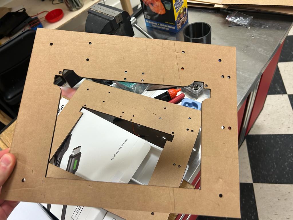
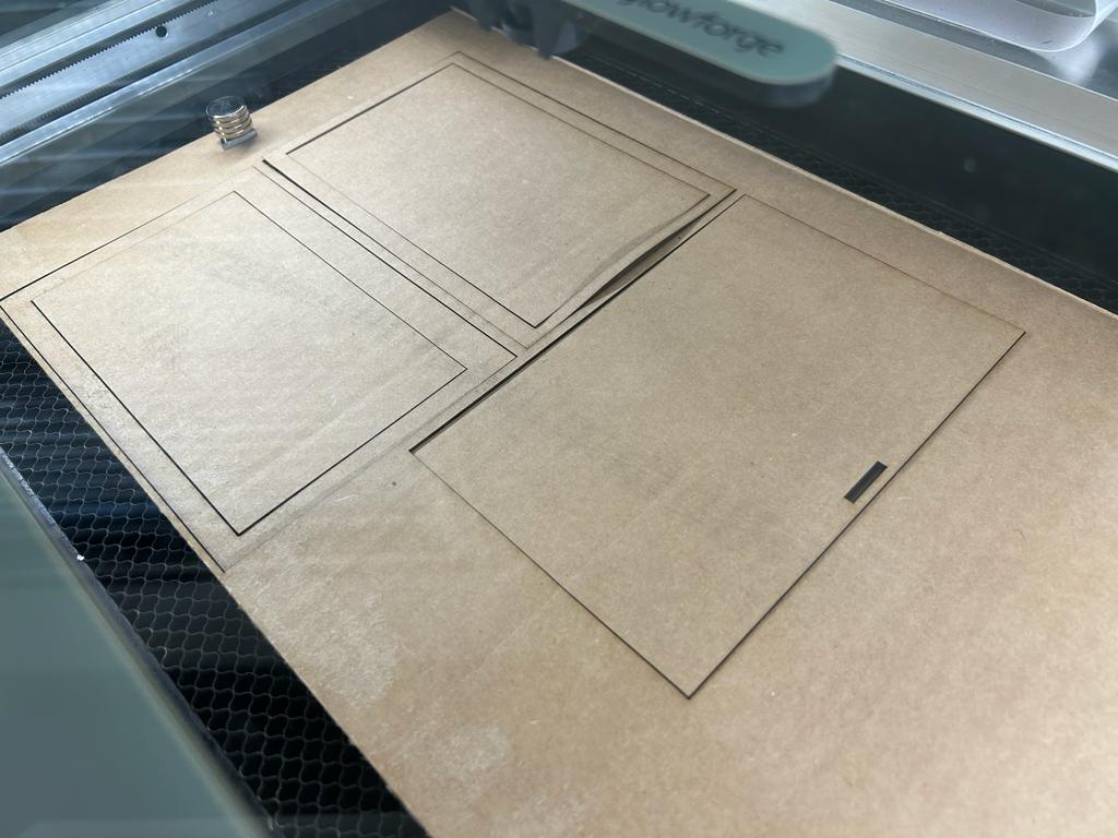
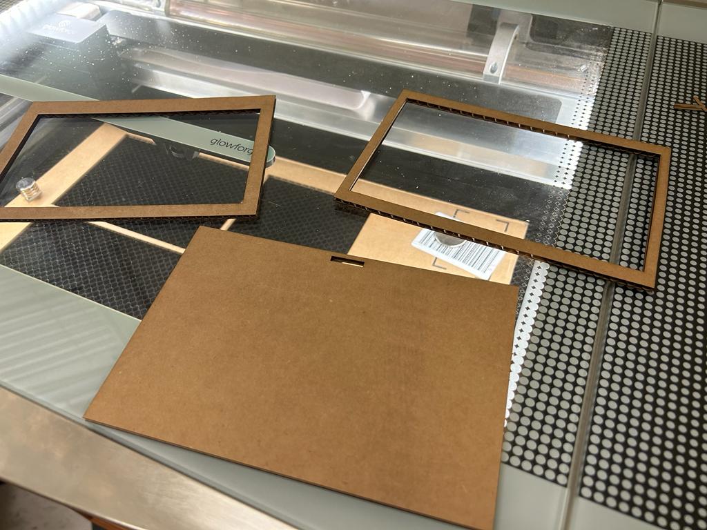
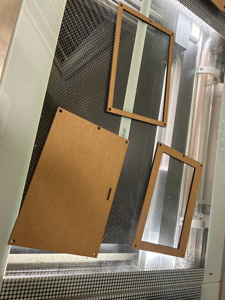
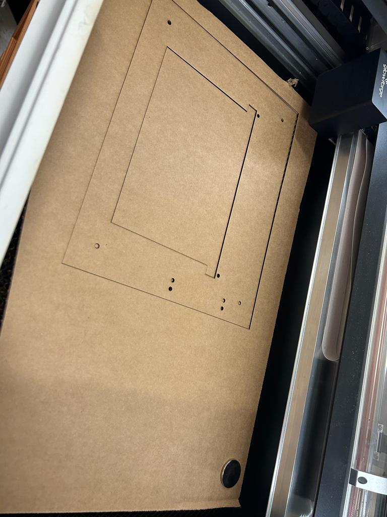
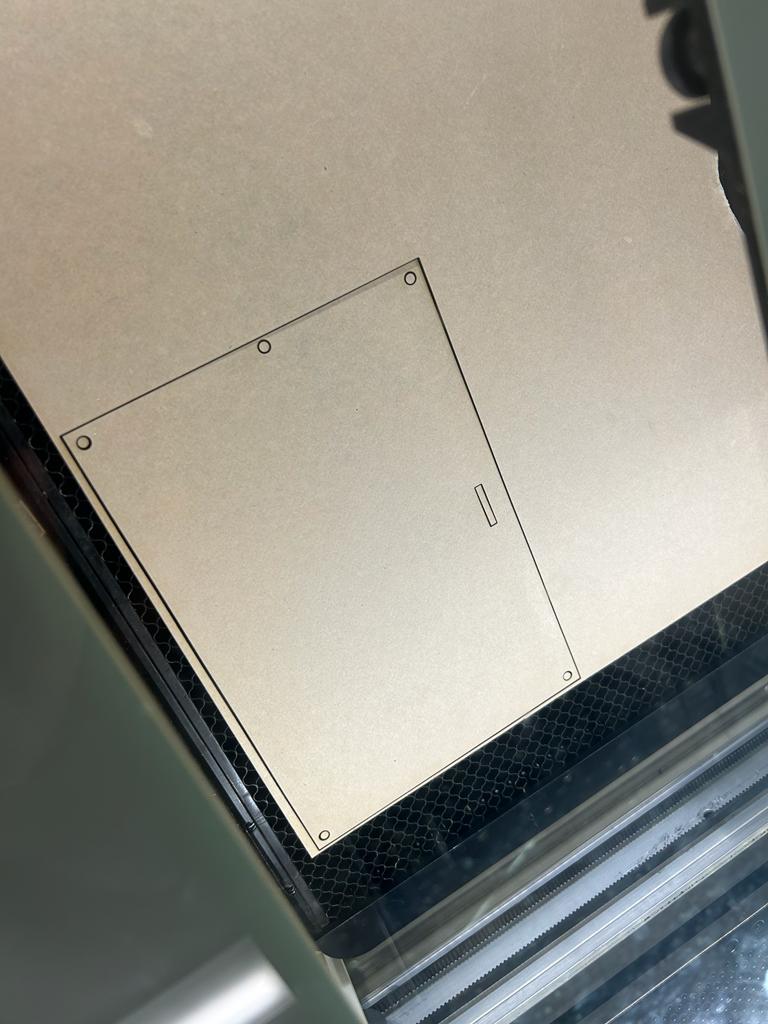
Laser Cutting
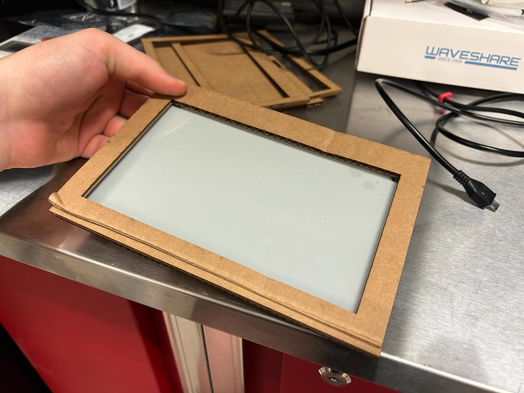
I used cardboard to test the design.
Didn't Fit
Iteration 2
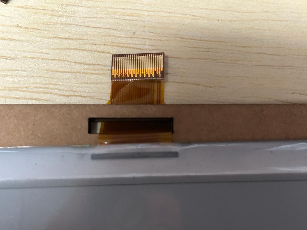
Design Adjustments
Ribbon cable hole moved so it's not covered up. Sizing slightly adjusted.
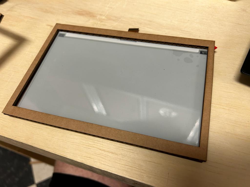
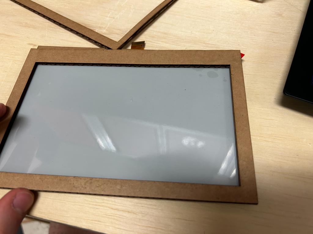
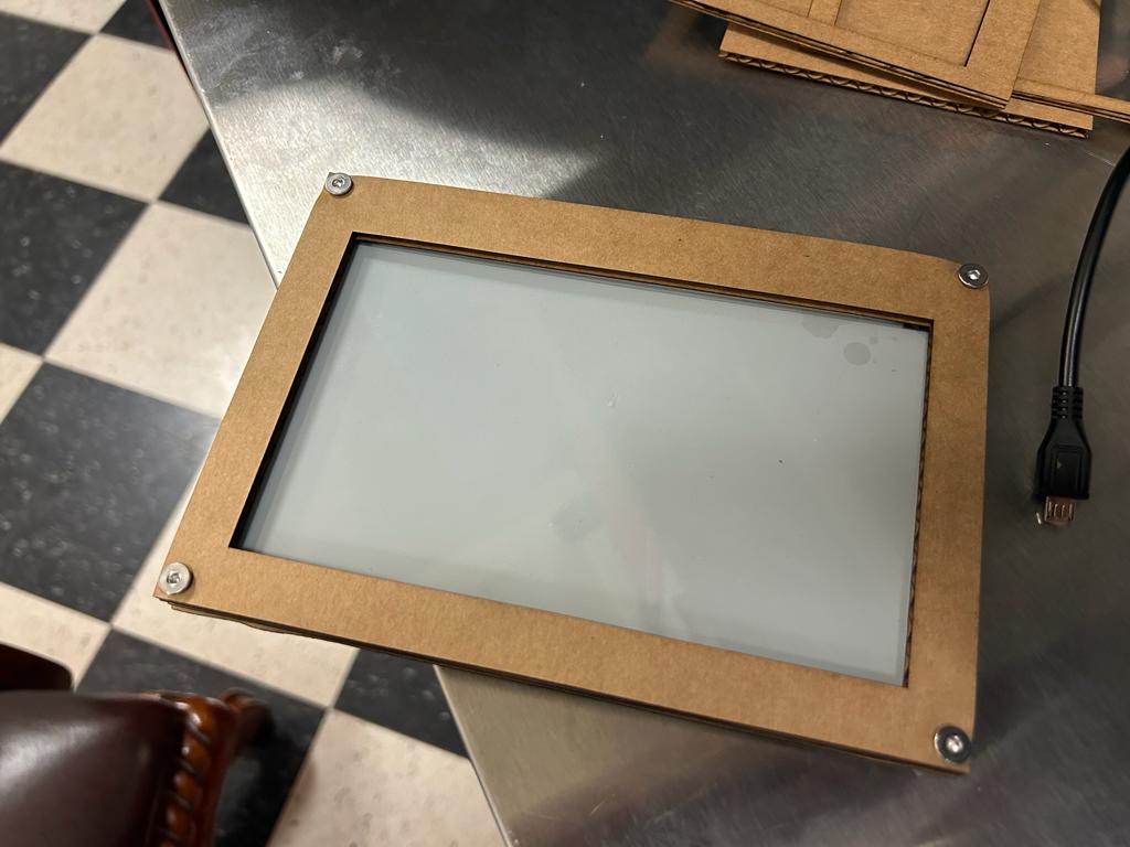
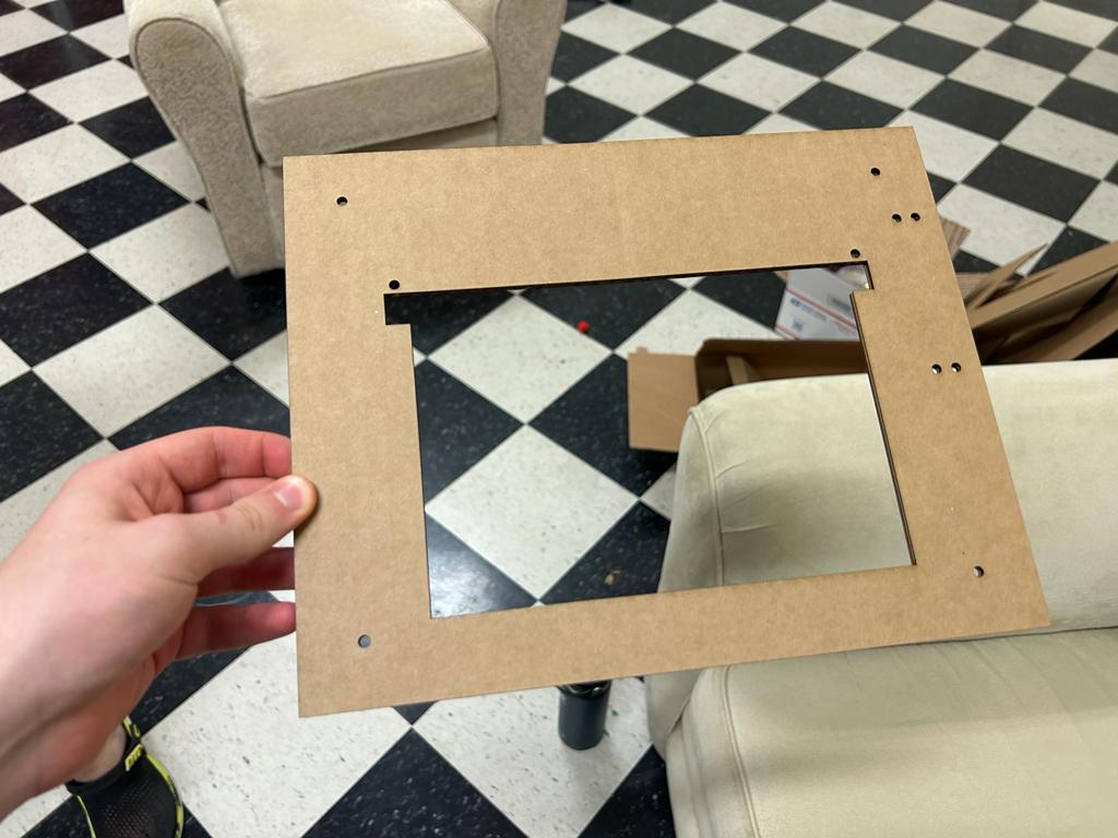
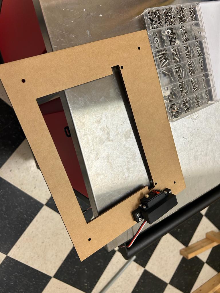
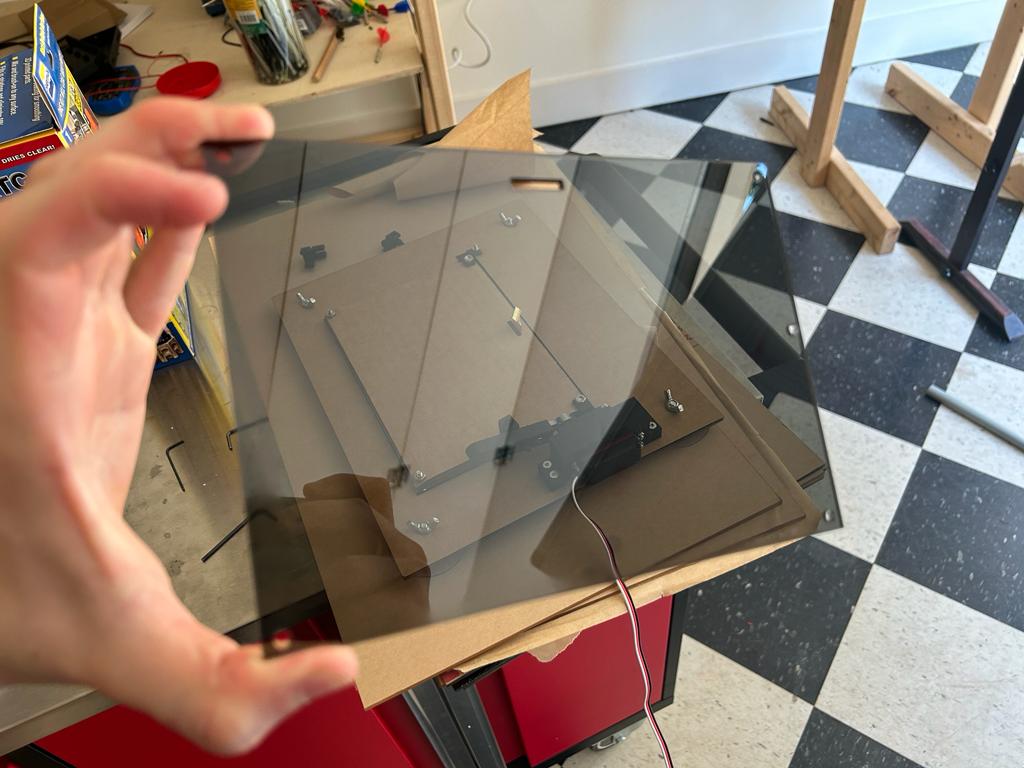
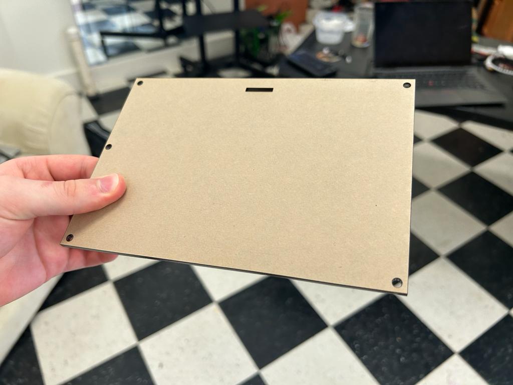
Fit Perfectly
It fit perfectly! Now I need to add screwholes.
Iteration 3
Design Adjustments
I decided to use M4X12 screws. I referenced Week 2 when I learned about screw naming conventions. I chose a nominal diameter of 4mm somewhat arbitrarily, but chose 12mm length specifically because the material is about 0.125in wide which is 3.175mm, and three pieces is ~10mm, and when I incorporate attachment to the servo, some extra screw length will be necessary.
Result
I had to switch to M4X16 screws as the M4X12 screws weren't long enough. These worked but I may end up using M4X20 screws in the final project. The case sometimes shifts a little bit, but adjusting the middle size slightly or have little pieces of rubber or dabs of hot glue should fix the problem.
Frame Mechanism
New Design Idea
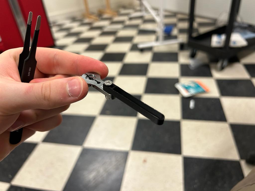
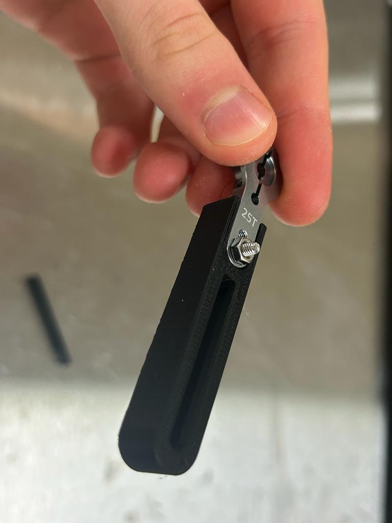
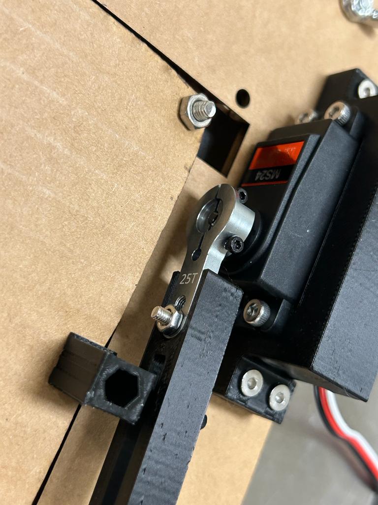
Servo Arm Attachment
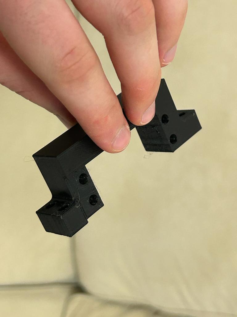
Iteration 1
Servo attachment screws are M3 so 3mm nominal diameter. Centers of two holes are 4mm apart.
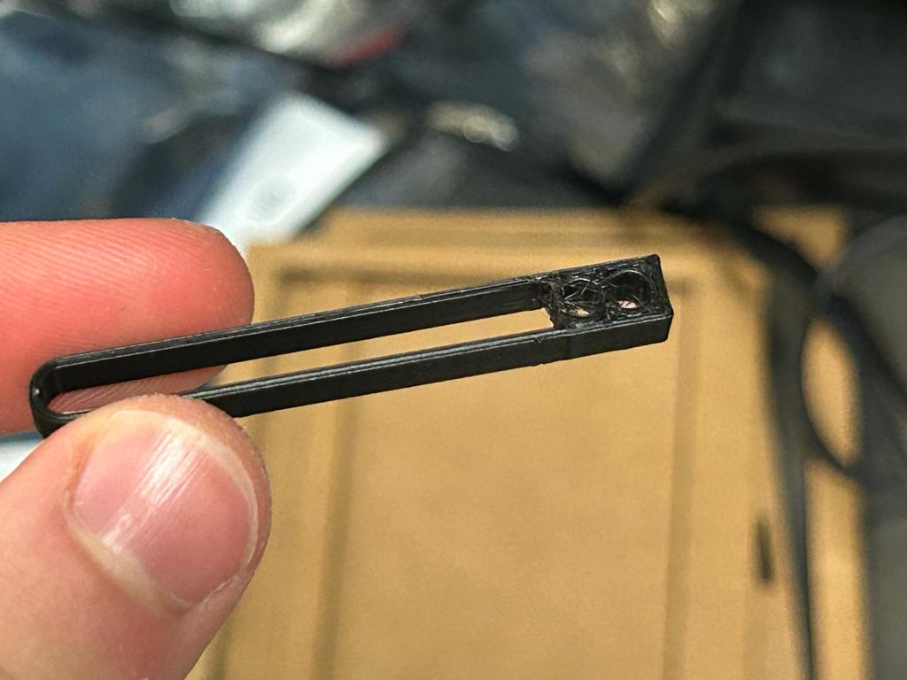
First draft of the design - realized can't have two screws. Still held fairly straight but wanted to be sure. I printed it on 100% infill. I oriented it flat so that I don't have to use supports, and it will be less likely to break from torque from the motor.
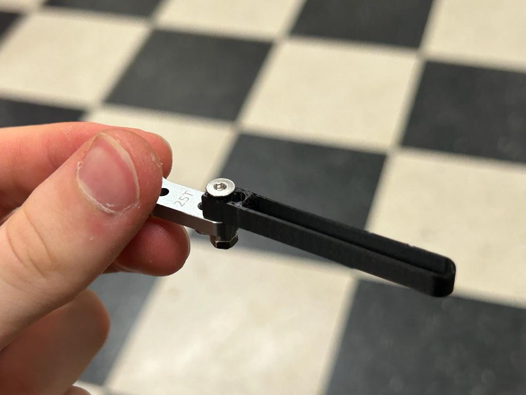

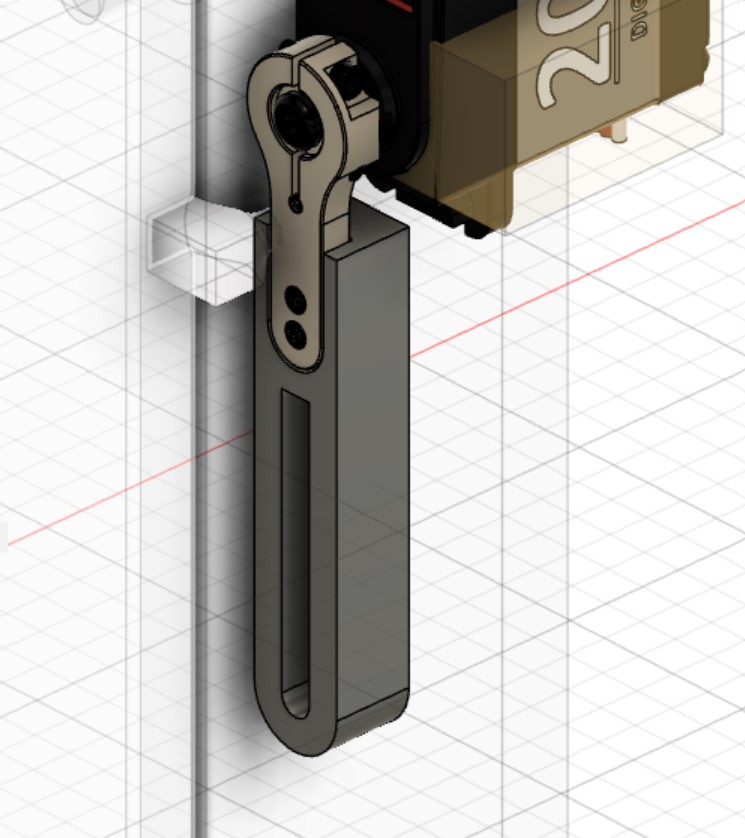
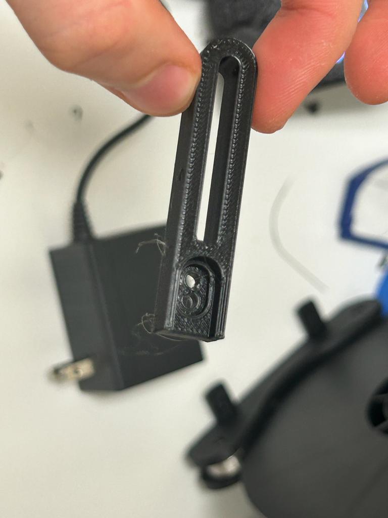
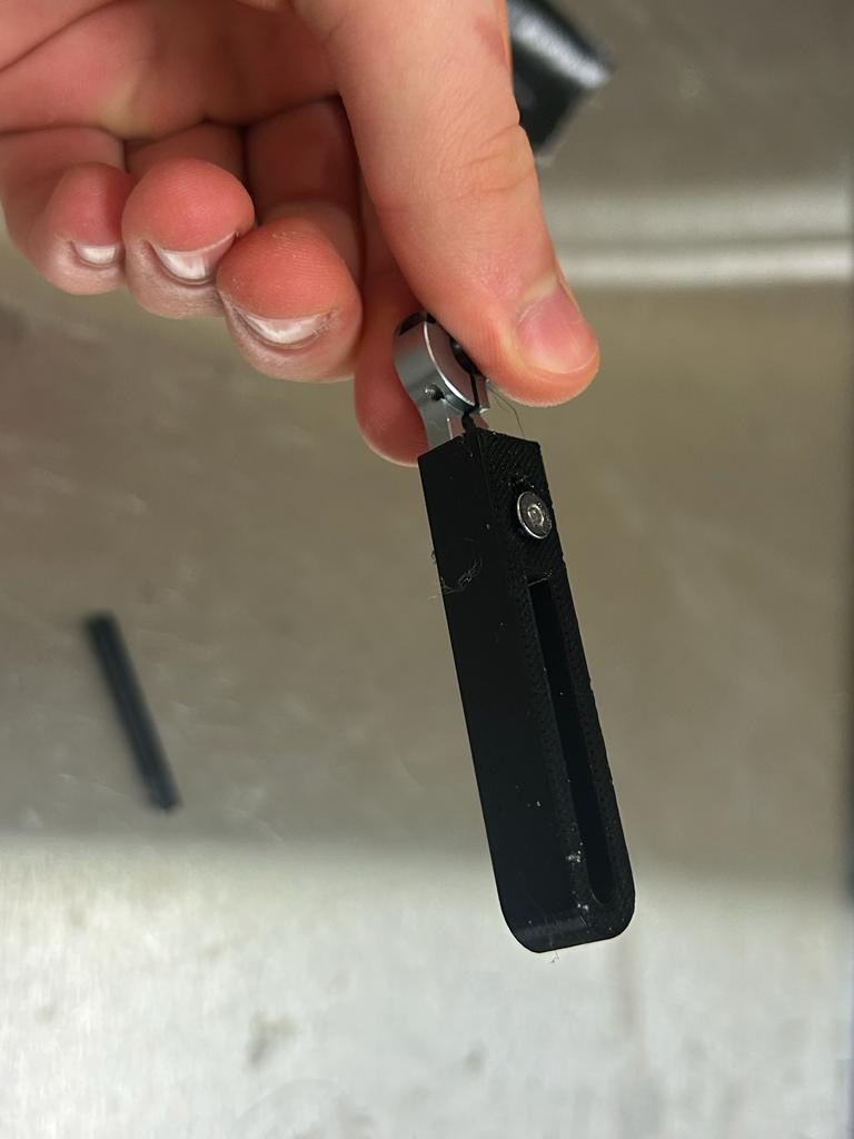
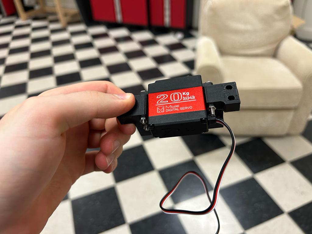
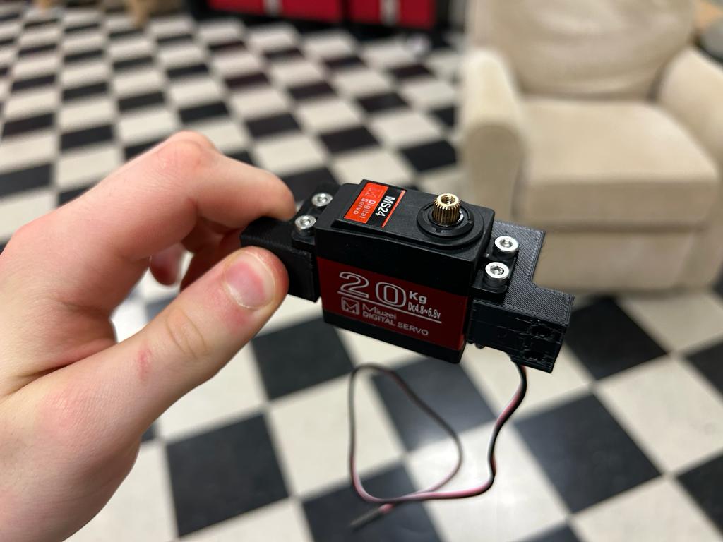
Iteration 2
Found this design. I first set the tolerance for the fit to 0.25mm parametrically. I also just left both screwholes for now as I'm not sure which one is optimal to use. I printed it on 100% infill. I'm also considering printing in Nylon for the final piece to make it stronger. I'm considering adding more area around the sides that are cut thin because of the fit onto the motor.
Huge success!
Case Attachment
Iteration 1
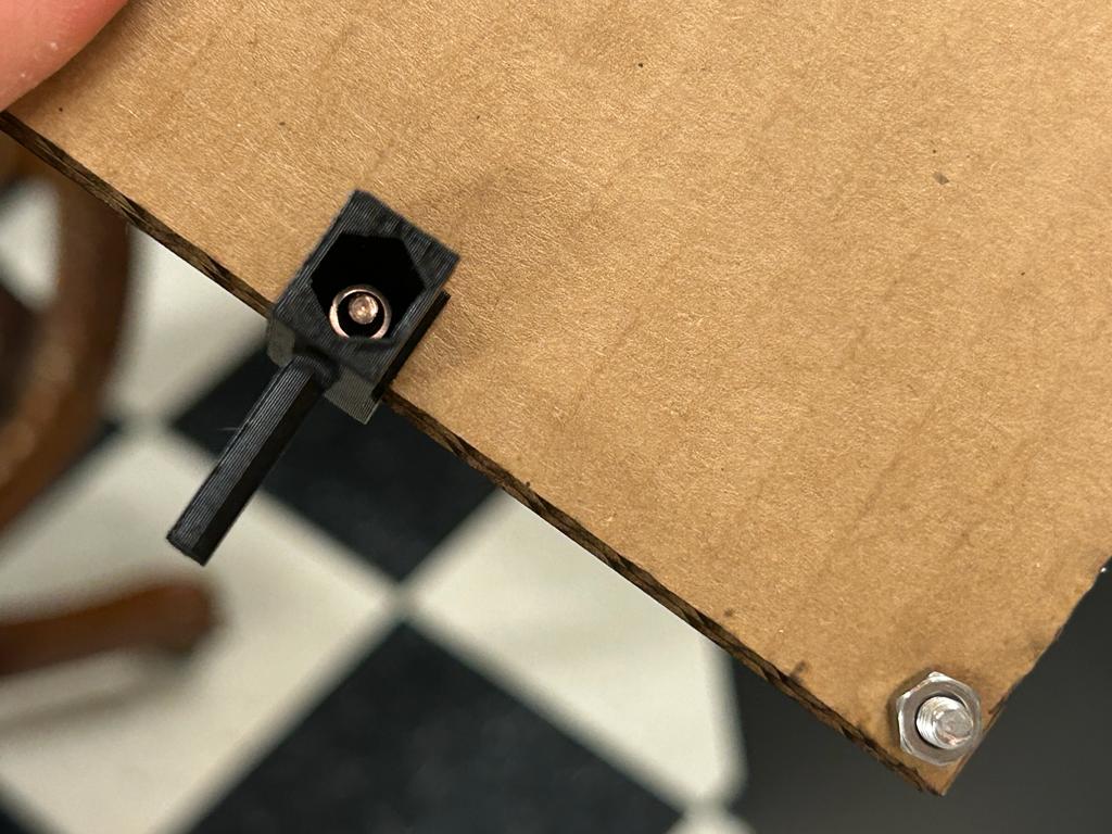
https://grabcad.com/library/m4-hex-nut-1
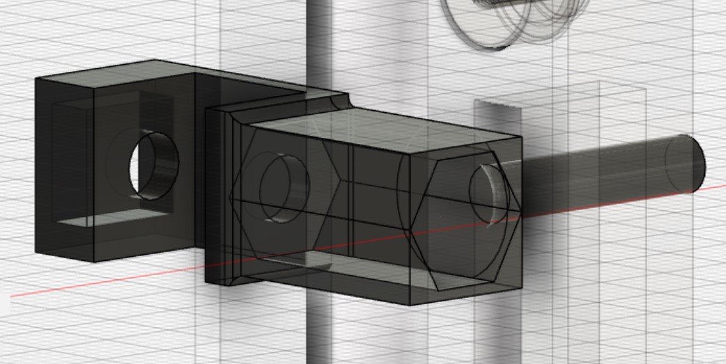
I also updated the case design to include another screwhole. I forgot to add an offset or tolerance from the 3D-printed piece to the case.
The piece fit snugly and the hex nut fit. I decreased the tolerance slightly from 0.4mm to 0.2mm.
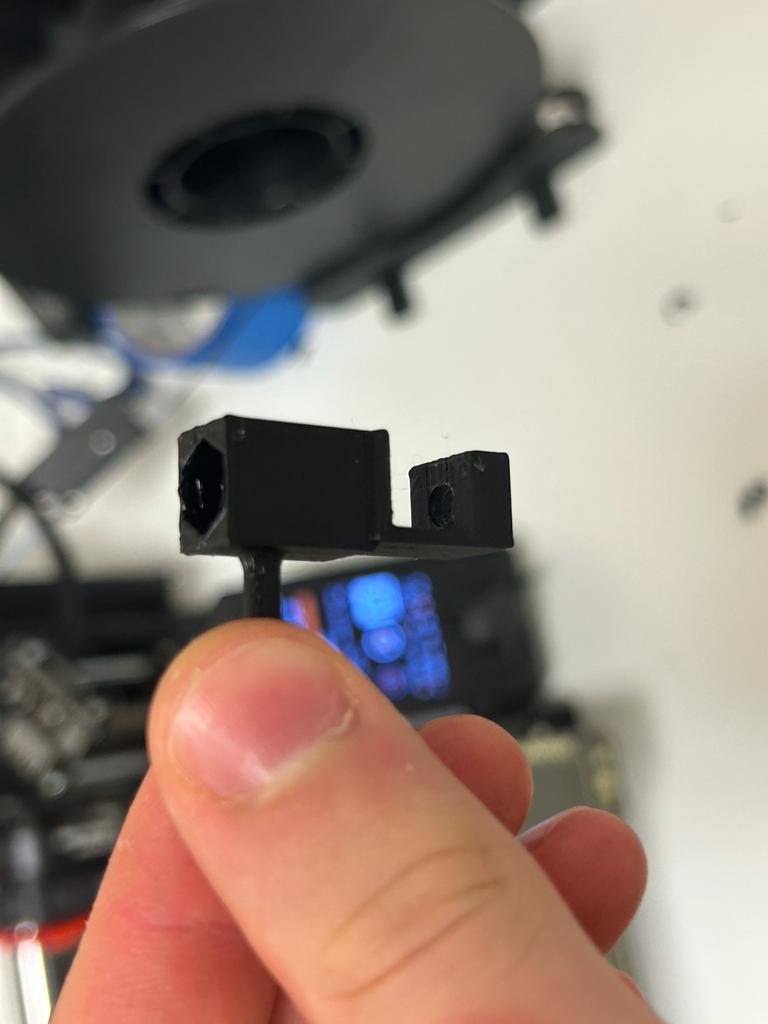
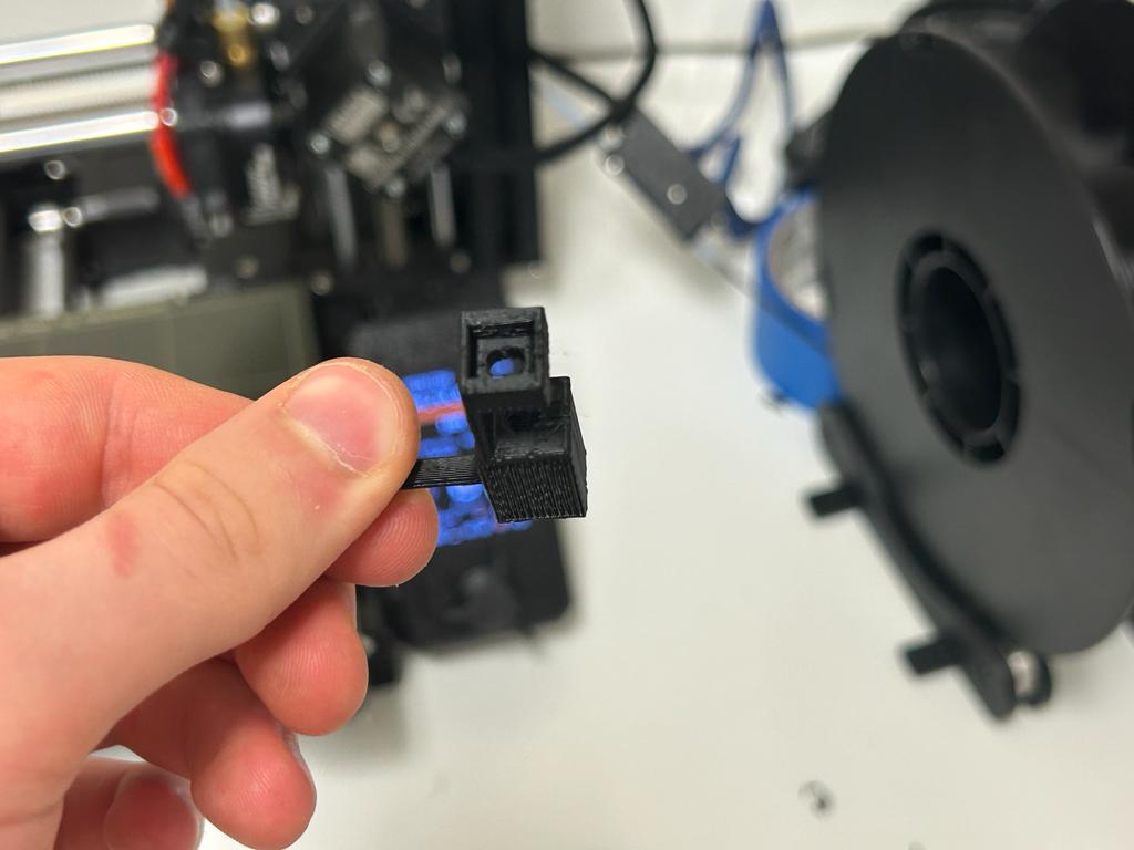
Here's the first iteration case attachment on the old version of the case without the screwhole.
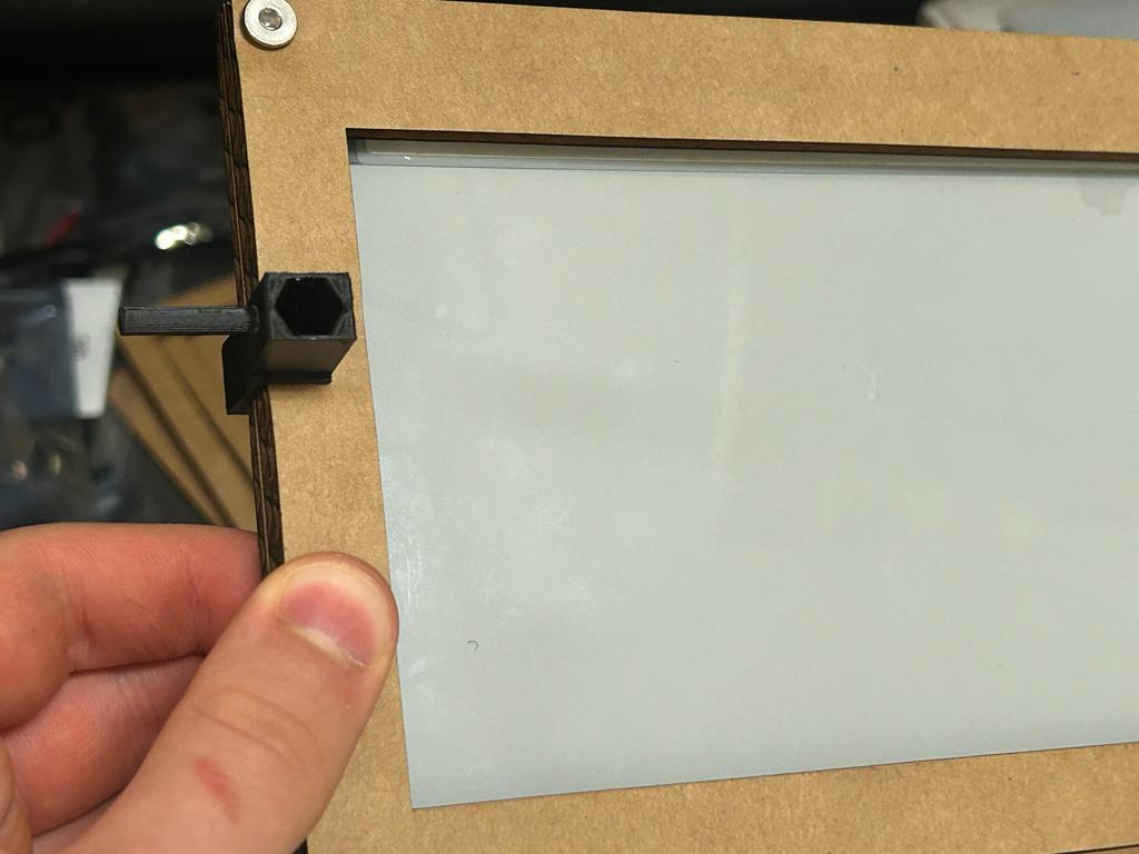
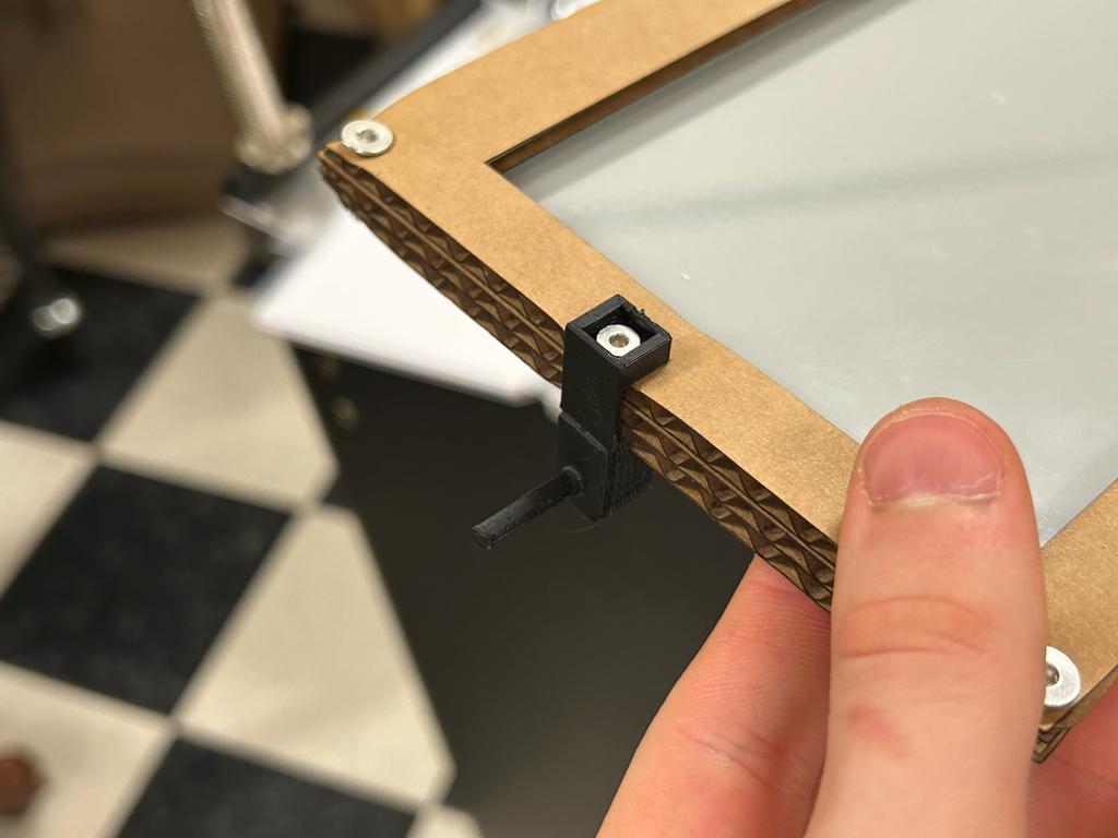
Iteration 2
This iteration was an improvement, however the fit was still small around the case, possibly an error in the manufacturing of the cardboard I was using. The PLA flexes slightly so this shouldn't end up being a problem. The larger issue is that the hex bolt hole is still too large, and it's very hard to tighten the screw. I changed the tolerance to 0mm since maybe the CAD model of the hex bolt I had found was problematic.
Here's the updated case.
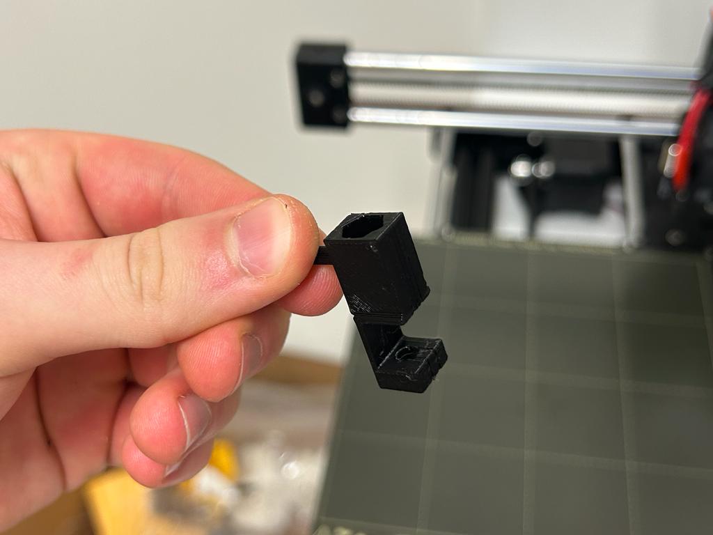
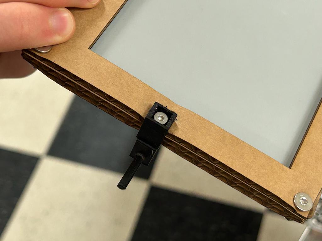
Iteration 3
The new tolerance still didn't work. I measured it instead of using the CAD model online and saw the diameter of the hex bolt was 2in. Currently it had a radius of 3.475mm = 0.1368in which should be 1in = 2.54mm. So I changed the offset to 2.54mm - 3.475mm.

Iteration 4
Now it was too tight of a fit. For the next iteration I added 0.5mm to the size.


Frame
This diagram revealed that my frame can be at most 16.75in tall. My current design is approximately 10in, so this shouldn't be a problem.
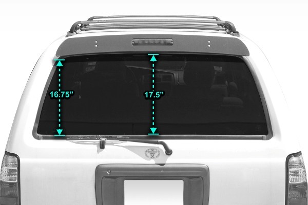
I also measured both the distance from the point or rotation of the servo to the end of the arm attachment, which was ~65mm and the point of rotation of the case to the case attachment, which was also ~65mm, and since the angle where the lines will be parallel and not overlapping will never be achieved with the design, there should be no problem with the arm length.
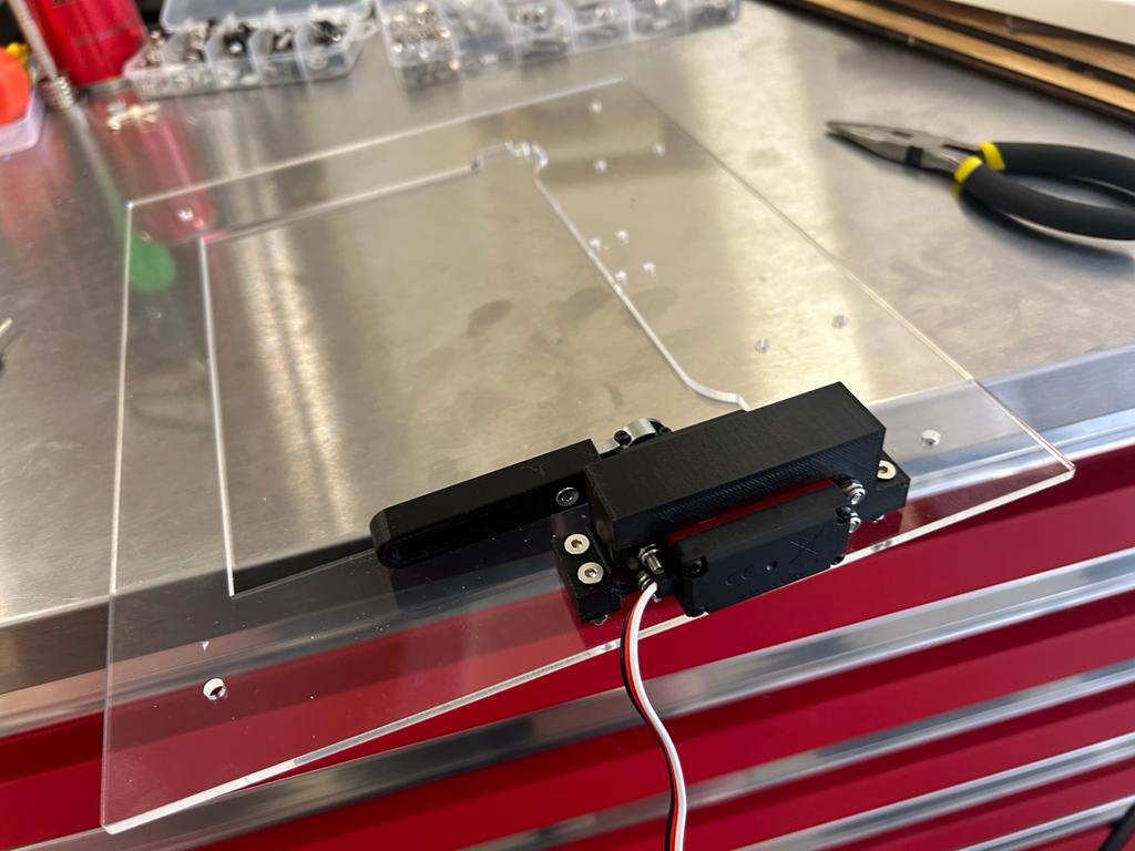
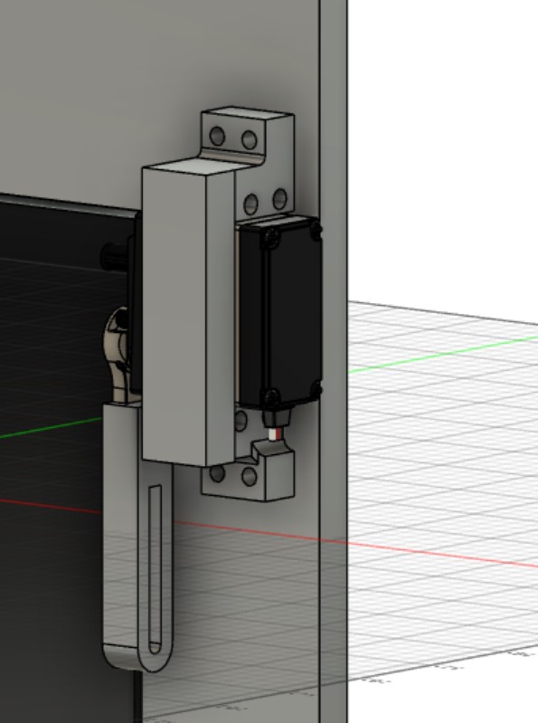
Servo Mount
Iteration 1
Found this design of a servo. Could also use the one from the other part
I had to make the frame slightly taller so that the suction cup and the servo holder's screws wouldn't overlap.
I decided to use M4 screws for this, as well. For future iterations I may add a hole indent for the head of the screw, but don't feel it's necessary for now, and I don't have this for the case itself since it's laser cut.
The holes on the servo motor are M3 screws. I just projected the holes from the CAD model to create the holes.
I also noticed that the servo arm was weirdly moved, and I'm not sure why this happened as I don't believe I've moved anything, but I have the STL model saved, so I'm not too concerned. After correcting this because of something that moved (I'm not sure what), the case attachment didn't line up with the hole, but the servo can always be at an angle, so this shouldn't be a problem.
I printed this piece with 20% infill for now, but will use 100% infill for the final part.
It worked perfectly!
Suction Cup Attachment
Iteration 1
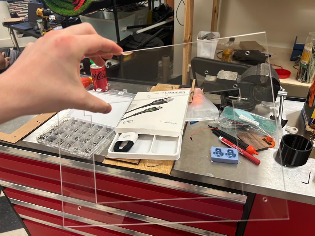
I tested the suction cup screws and found that they are M4 screws.
Since I had the entire frame designed in Fusion 360 and not Cuttle, I followed this tutorial to create a sketch of the vector lines and exported it as a DXF directly from Fusion 360.
It worked!

Pins
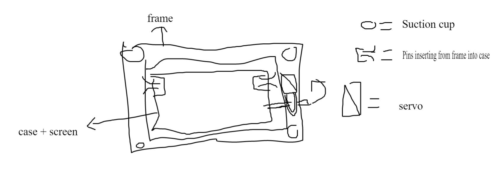
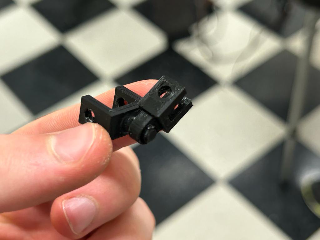
I decided to reverse the first design I came up with (pictured below) and have both the pin and the pin hole be 3D-printed. This way I could put the pin and the hole inside of each other before connecting it to the frame and case - otherwise, I would never be able to get the case in the frame.
I also realized that, up until now, I've been designing the case on 3/8in material. For now I'll change it to 1/8in but change to 1/4in if it turns out our lab has a greater abundance of that material.

Iteration 1
I referenced this article to make "floating" pieces in Prusa by merging the two parts then moving one individually by referencing the hierarchy. I set the print detail to 0.1mm and 100% infill. I see a blue line on the top of the circle of the outer-hinge, so I'm not sure whether the print will work, but I'll try it.

The print-in-place design worked first try!
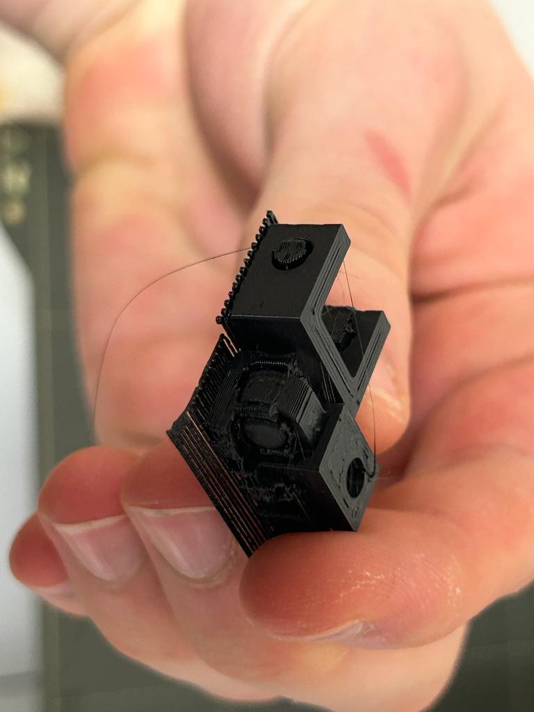

The design worked very well, but the holes were very tight for the screw. It still worked, and I might increase the size of the hole be 0.5mm if it causes problems throughout the rest of the prototyping process.
I re-printed the same piece for the second side.
Iteration 2
I increased the hole size by 0.5mm, changing the diameter from 4mm to 4.5mm. I also rotated it temporarily in Fusion 360 before exporting into Prusa so that I wouldn't have to merge and reposition the parts before slicing.
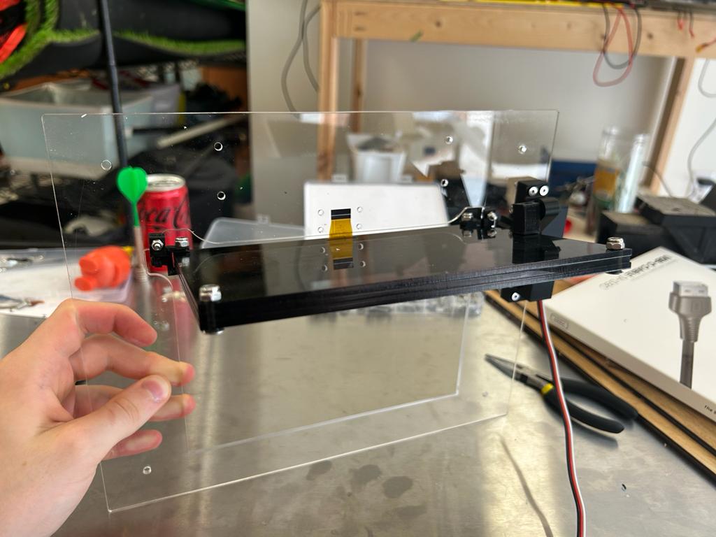
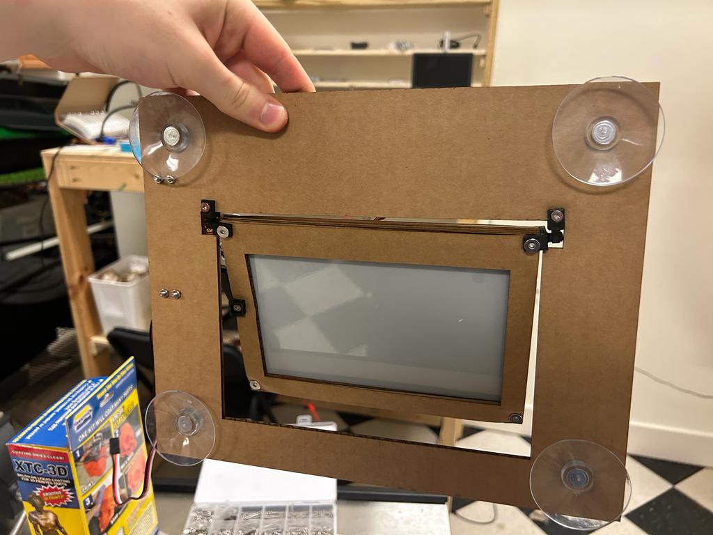
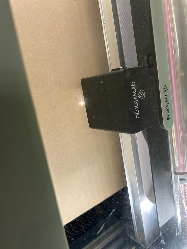
Putting It Together
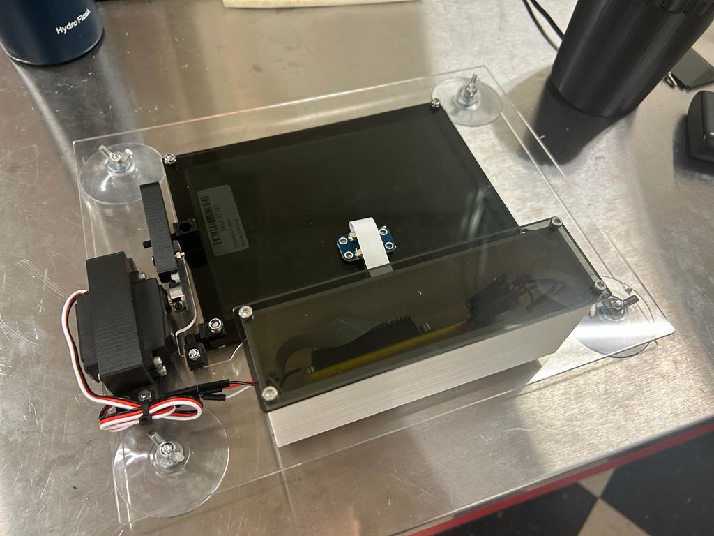
I assembled the design and it fit together perfectly!
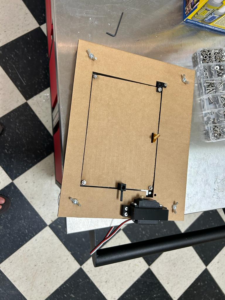
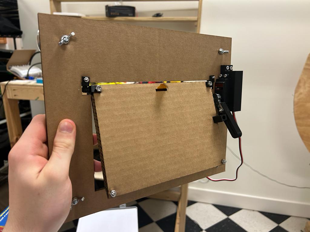
The product will not be on the driver-side window in the end, I'm just testing it on a window in the picture below.
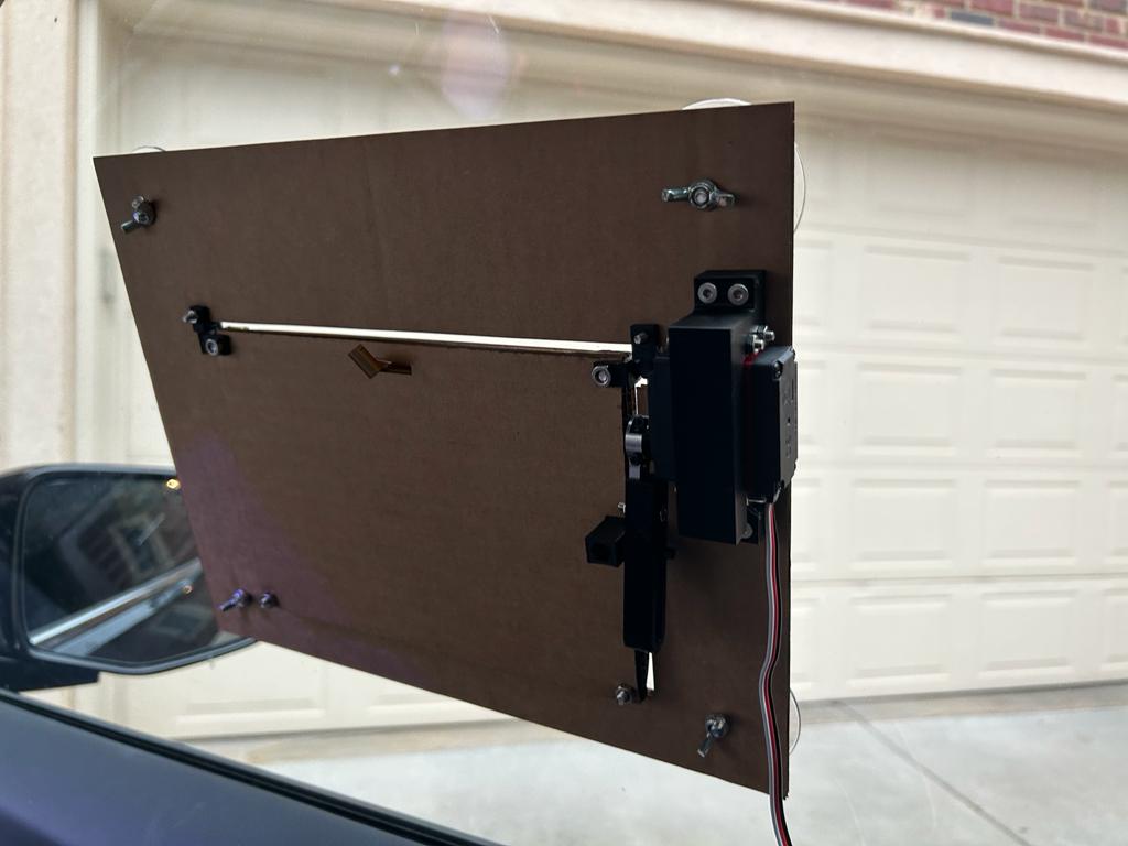
When I hooked up the electronics, it worked!
But the 0 wasn't at the correct spot, so I set the servo to 0 in the code, took off the arm, and put it back on at the right spot.
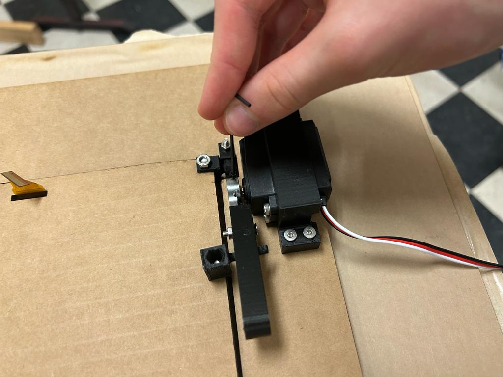
now it was correct!
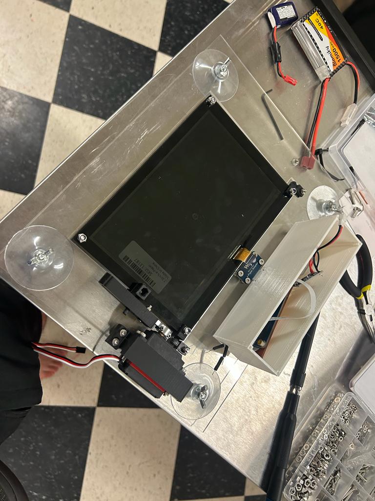
Electronics Case
Iteration 1
The circuit board is slightly less than 100mm X 30mm. To account for the 43mm long bluetooth module, is should be at least 150mm X 30mm. And to give extra room for wires, it should be at least 150mm X 50mm. Since the battery is 55mm X 5mm X 75mm, the case should be enlarged to 150mm X 40mm X 60mm.
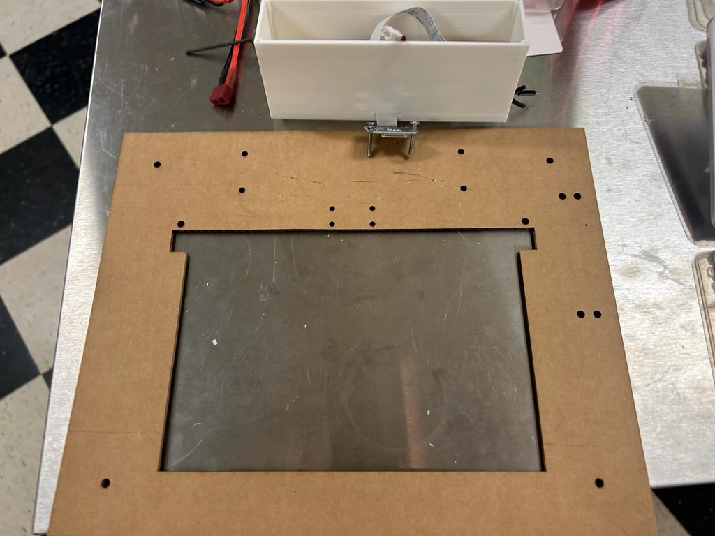
I also added four M3 screwholes for the ribbon cable adaptor. I used measurements of 2mm from the outside of the hole to the edge of the board, 13.5mm from the outside edges of two holes vertically, and 21.5mm between the insides of the holes horizontally to create the deisgn. In the end, this adaptor caused stress on the ribbon cable which ruined another one of the displays. I ended up using adhestive to attach it to the back of the display case.
The 3D-printed threads worked sufficiently, although if tightened too hard, they lose the ability to tighten at all. After experimenting with both hex bolts and 3D-printed threads in my project, I've found that hex bolts tend to work more smoothly.
Iteration 2
First iteration - screw holes very tight fit but screwed in tight. The ones without threads couldn't fit an M3 screw in, so increased size by 0.5mm.
Also realized I forgot the add a hole for the servo motor cables. I used this calculator to figure out the diameter of the hole for three 1.5mm wires, and a 4mm hole worked! However, pulling the heads of the wires through the small hole was not easy, but they never accidentally were pulled back into the electronics case.

Iteration 3
When I cut the lid out of acryllic, the screwholes were too close to the edge and broke, so I redesigned it in the next iteration to have more space around the screwholes. I also added more area around the screwholes in the design of the case, but I never ended up printing it.

Iteration 4
I implemented the changes described in the previous iteration by adding more area around the screwholes.

Iteration 5
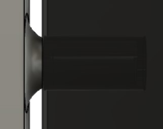
I added a switch in the power wire coming out of the TP4056 Module (not from the battery so that the battery could charge even if the switch isn't turned on). I added a 6mm hole for the switch and secured it with a washer and bolt. This worked first try!

Iteration 6
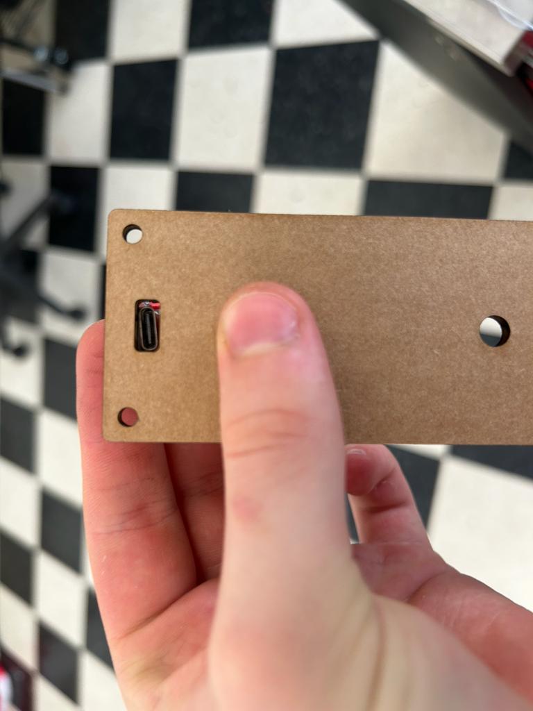
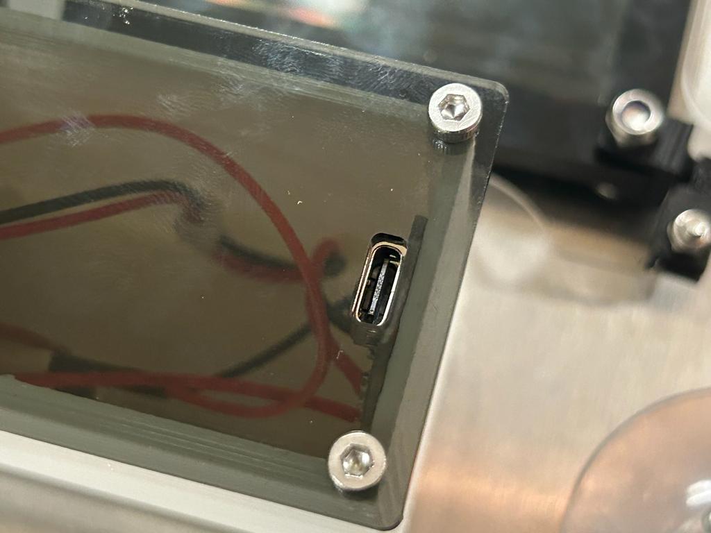
I added a hole for the charger. It took several tried to get the dimensions exactly correct. I temporarily held the charger in place using nitto tape, but I modified the design of the electronics case to include screwholes. Without the screwholes, it is difficult to plug into the charger without it moving, and removing the lid before charging is recommended.


Cutting Acryllic
Iteration 1
To cut my 1/8" acryllic, I used the Medium (*color*) Acryllic setting in Glowforge. I had to be sure to turn off the custom cardboard setting on the individual SVGs even though I selected the material overall.


Iteration 2
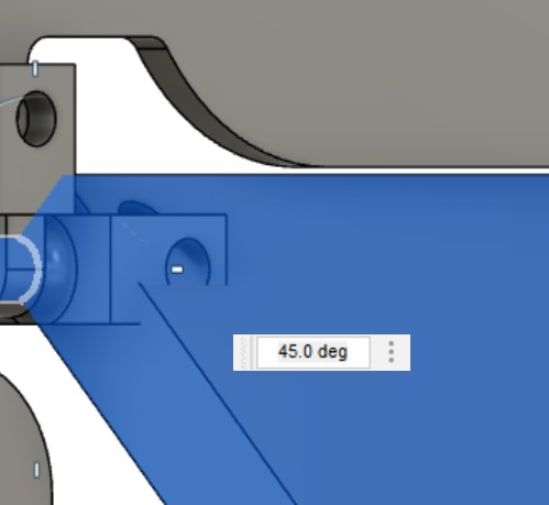
I had a problem where, when the screen turned, the bolt on the hinge would collide with the frame. I measured that the distance from the axis of rotation to the end of the bolt is 11.5mm, so to be safe, I added a hole that's 13mm from the axis of rotation.
I also noticed that I accidentally moved the frame slightly in Fusion 360 before making the elecrtonics box, so it was sightly off center. I was having trouble correcting this problem it so I just left it, as it didn't make any noticeable difference.
I also ensured that the new design would preclude collisions in Fusion 360.
The new design worked well! I had also added fillets.