Fixing The Design
Before milling my board for this week, I realized some flaws with the design I created during Week 6 in EagleCAD. I realized that making a custom component wasn't necessary since I couldn't solder the button directly onto the board.
Instead I looked for pins that I could solder onto the board. I later learned that the type of pin I was looking for is called a Pin Header. For my final project, though, I'd like to use a more professional solution such as a Ribbon Cable, though I'm not sure this is an effective choice for my setup.
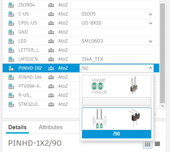
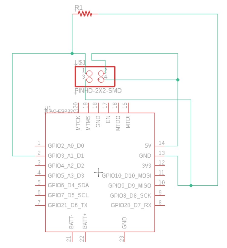
I looked for a 2-Pin Header component in EagleCAD but only managed to find what I though was correct.
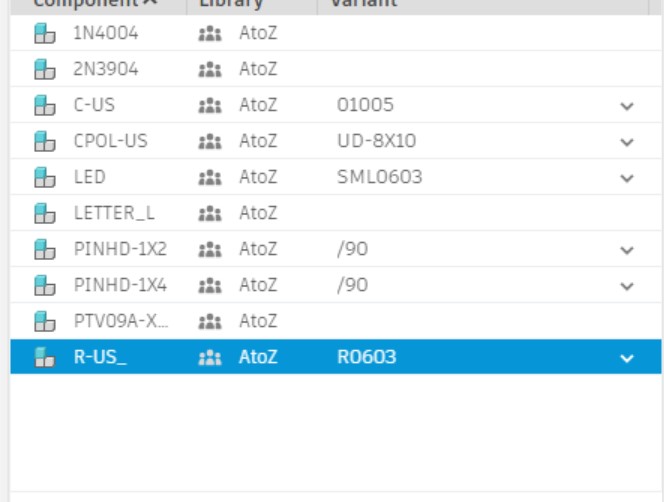
For now I just chose this resistor hoped it was the right size.
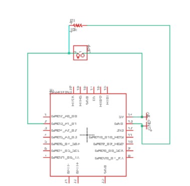
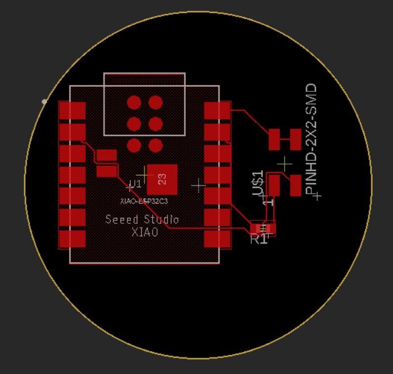
I autorouted and made sure t press Continue... not Select.
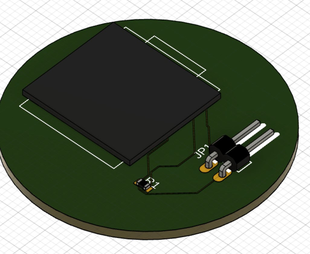
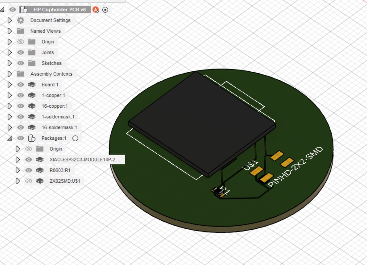
I pressed the Push to 3D PCB button after saving.
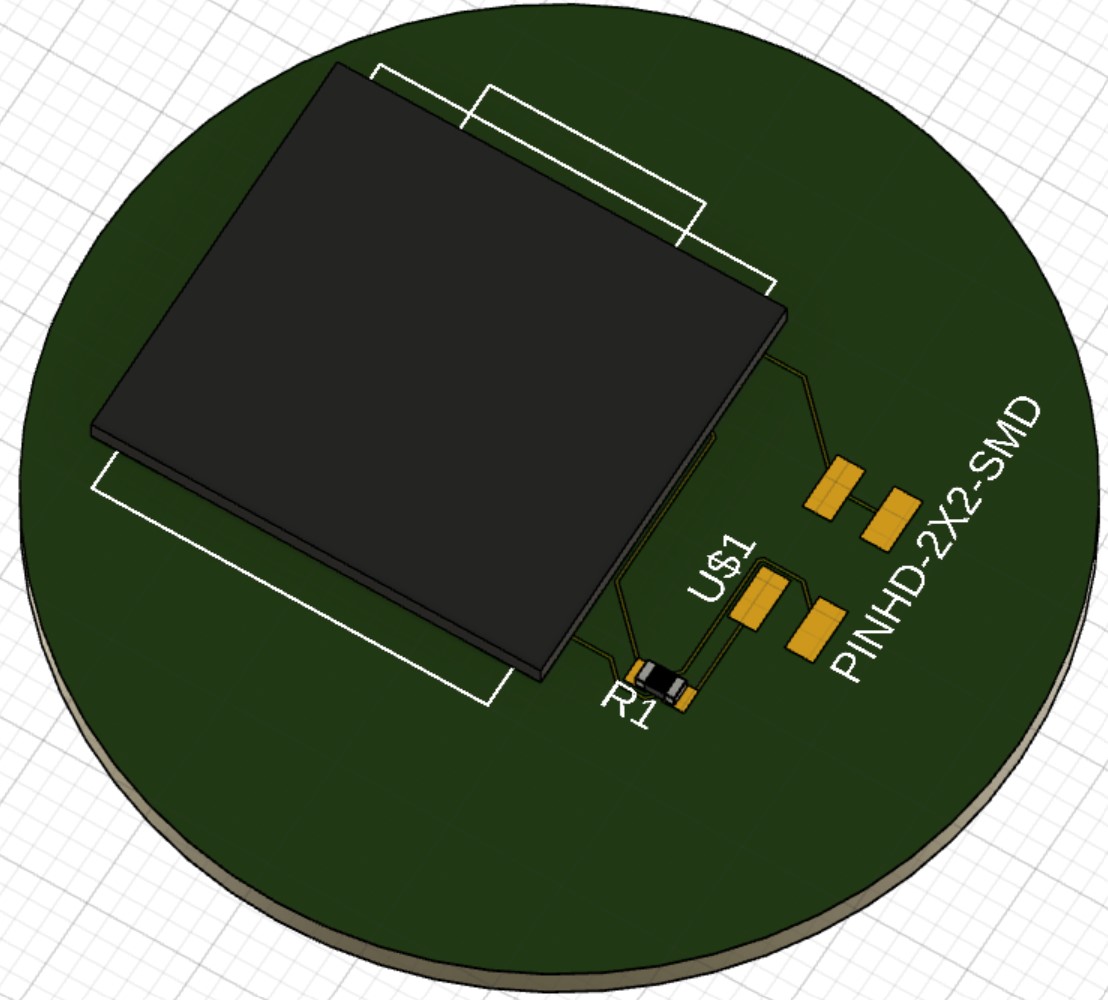
I then realized that the Pin Header was through-hole when I wanted it to be surface mount! (I learned the SMD stands for Surface-Mount Device, and it commonly used in component abbreviations).
I downloaded the pinhead library which was already in EagleCAD, which didn't have surface mount components.
I also downloaded the Connector library and had the same problem.
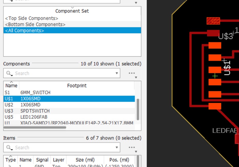
I then opened Dr. Taylor's XIAO Seeed RP2040 development board and saw he used the 1X06SMD component from the fab library I had installed. I looked in the fab library and found a component that I think will work. It's 2x2 instead of 1x2 but I think this will be ok, especially if I decided to use another button in the future.
I hid the default cube on the 3D PCB.
I then added an external power and ground as header pins to my design.
Exporting The Board
I followed this tutorial and went to Layout Editor > Manufacturing > Manufacturing Preview > CAM... > Gerber but then learned that I can simply use the all-in-one export instead - continue reading here.