Parametric Construction Kit
The Plan
To create a parametric construction kit that can be assembled in multiple different ways, I decided to design two different pieces using Cuttle that can create lots of different angles when joined.
Cuttle Design
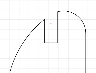
The Basic Shape
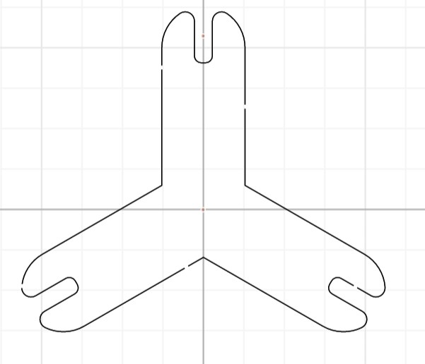
To accomplish this, I started by making a vertical line in Cuttle and using the Modify > Rotational Repeat tool to create multiple lines around the origin. I then clicked on the line in the hierarchy and unchecked the hairline option under the Stroke menu. I then created a project parameter for the arm thickness and set the width of the line to that parameter. I also set the cap type to round. I also created a parameter for the arm length and set the length of the line to it.
Next I created a rectangle and tried to subtract the rectangle from the original shape, yet when I used the Modify > Boolean Difference command, I was getting very strange results. I realized that the geometry for the original shape was still just lines, so to convert the lines to the outlines with thickess, I selected the original link and used the Modify > Flatten command. Then the boolean difference worked.
I positioned the center of the rectangle on the end of the original line, but the rectangle wouldn't move when I changed the parameter for the length of the arm. To fix this temporarily, I made the y-position value of the rectangle -armLength so the center would always stay on top of the outermost endpoint of the line. For some reason, though, the end of the line was slightly offset from the center of the rectangle. When I opened the line in the hierarchy, I noticed that Anchor 2 had a y-position of -0.98 not -1. After correcting this, the position issue ws fixed!
Then I deleted the rotational repeat and decided to add it back after finishing the subtracted rectangle. I created a slotDepth parmeter to determine how long the connecting slot would be, and set the scale of the rectangle to Vec(materialThickness, slotDepth). I also set the position of the rectangle to Vec(0.00, - armLength - (armWidth/2 - (slotDepth/2))) so that the top of the rectangle would always be right at the top of the arm.
I added a rotational repeat back to the highest-level group created from the Boolean Difference, created a numArms parameter, and set the repititions of the rotational repeat to numArms.
As Neil discussed in the lecture (~42:00), having rounded corners and creating a chamfer press-fit joint is better than one with sharp corners because the angle doesn't have to be exactly correct when fitting the joint together, and the slanted edge will slightly compress the material so that it fits together extremely well. I didn't want to use one of the snap-fit joints because I wanted the construction kit to be easily disassembled and reassembled without much effort or risk of breaking parts.
Joint Types
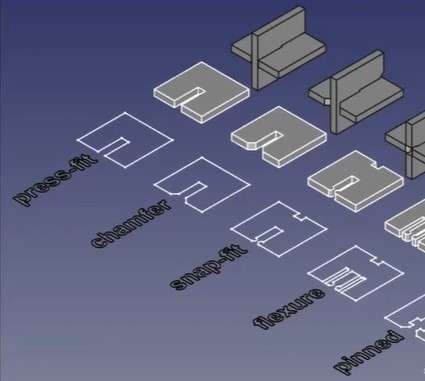 (from Neil's lecture)
I ended up creating a fillet instead of a chamfer mainly because this was very easy to accomplish in Cuttle, but looking back, I feel that a fillet is probably more aesthetically pleasing and fits with the overall rounded look of the pieces better, and having tested the real parts, it seems to work fine.
To create the fillet, I selected the highest-level group and used the Modify > Round Corners command. I set the radius to a new project parameter called filletRadius.
Retrospective Revisions
I also went back and created a project parameter called slotWidthOffset in case I wanted to test different offsets for the width of the slot in different materials. I updated the formula of the scale of the cut-out rectangle to be Vec(materialThickness + slotWidthOffset, slotDepth).
I moved the armLength, armWidth, and numArms parameters to the component-specific parameters for Component A. To accomplish this, I had to make new parameters with the same name under Component A (which automatically added a 1 at the end i.e. armLength1), copied the old values, deleted the original parameters, then removed the 1 from then name. The design disappeared after removing the old parameters, but came back once I had renamed all of the new ones to what the formulas expected.
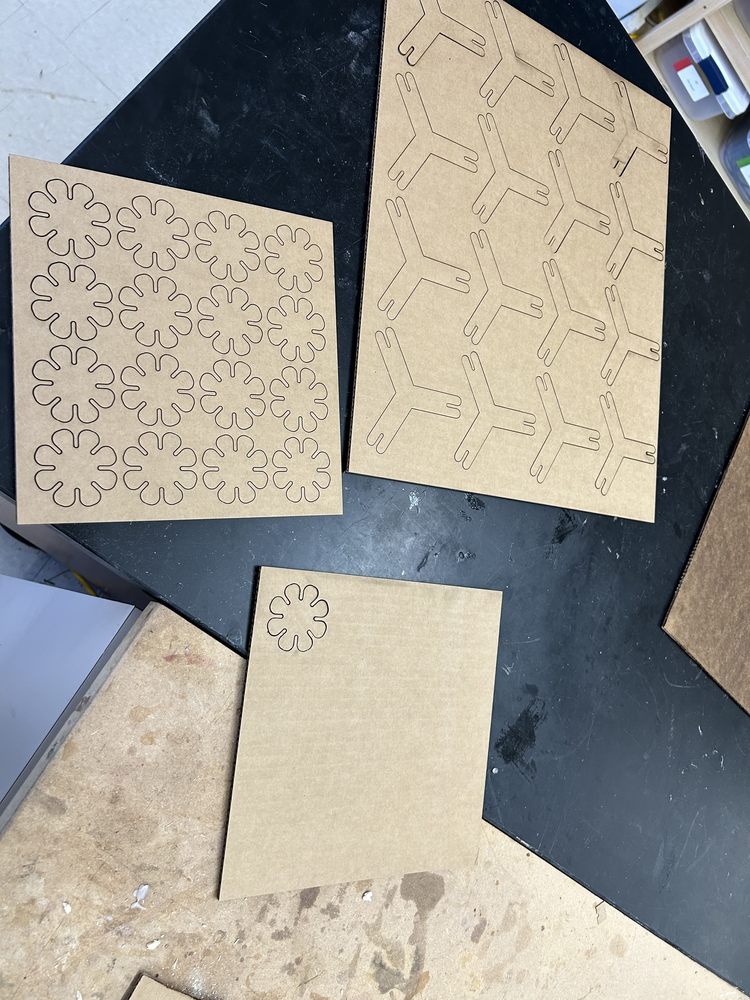
I renamed Component A to ProngedConnector and created a new component called JointConnector.
I also went back and checked the stroke result option under the flatten command in the ProngedConnector component. I then selected the highest-level object and used the Modify > Boolean Union command.
Another Component
In the new JointConnector component, I created a circle and hooked it up to a new parameter specific to the component called diameter. I also dragged in a new rectangle. I set the scale of the rectangle to Vec(materialThickness + slotWidthOffset, slotDepth) and the position to Vec(0.00, -diameter/2 + slotDepth/2), using very similar logic as for the first component's rectangle.
I created a numSlots parameter, used the Modify > Rotational Repeat command on the rectangle, and set the repititions option to numSlots. I then did subtracted the two objetcs using teh Modify > Boolean Difference command.
More Parameter Cleaning
Next, I created rounded corners using the Modify > Round Corners command and set the radius option to filletRadius. On second thought, I went back and made a separate parameter for the fillet radius of each component (since the component parameter had the same name as the old project paramater, I didn't need to update the formulas).
Kerf
I created a parameter to account for kerf of the laser cutter. I used the average kerf my group calculated of 0.0071in for the parameter's value.
First, I tried to use the Modify > Outline Stroke command to offset the components, but this created a new line and kept the only one as well, which I didn't want. Then, I trieed the Modify > Expand command and this worked! I entered the kerf parameter for the distance option. I also did this for the ProngedConnector component.
I then realized that the design should actually only be expanded by half of the kerf because then the edge of the removed material would be right where I want the component to start, not offset by an extra half of the kerf. So, I modified the distances in the two expand badges to kerf/2.
Here is a link to the final design in Cuttle! (This link includes changes made in the Cuttle Scripting section of this page)
Testing The Design
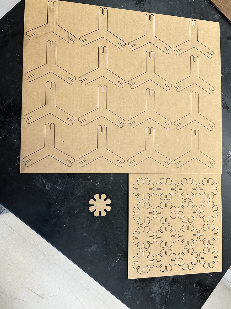
Laser Cutting
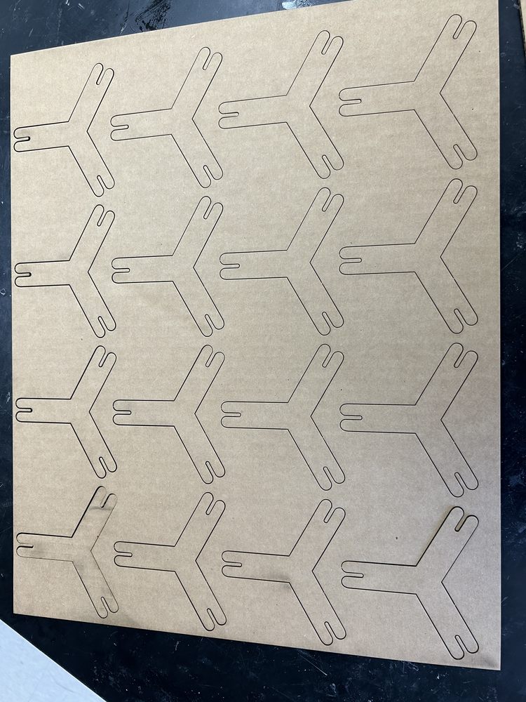
To test the design, I exported an SVG for each component from Cuttle, uploaded the SVGs to Google Drive, downloaded them on a computer connected to the laser cutter, created a new CorelDRAW file, right-clicked and selected Import, and clicked twice to import each SVG. I learned that if I click instead of drag when importing a file into CorelDRAW, I can keep the original dimensions.
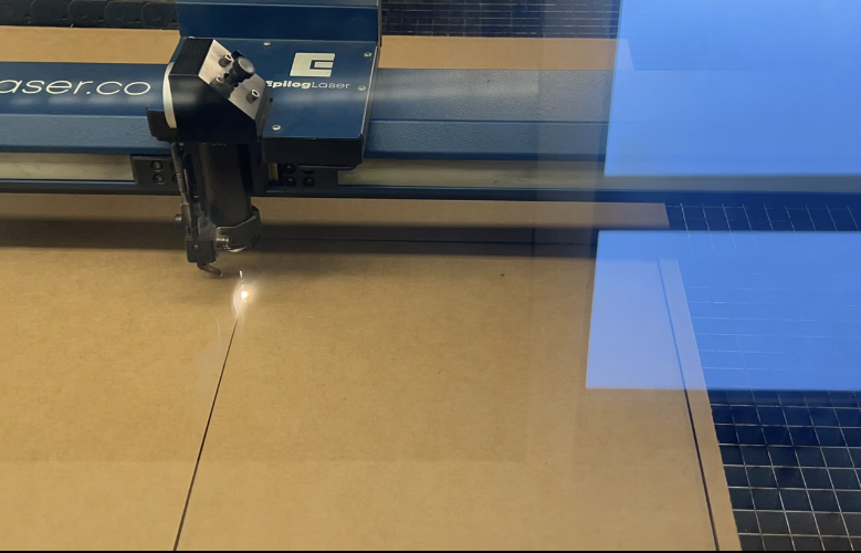
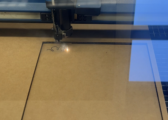
I then set the lines to hairline width, moved them close together, and set them to cut!
The laser was already focused so I just needed to put a piece of scrap cardboard in the machine and line up the design where I wanted it to be cut out.
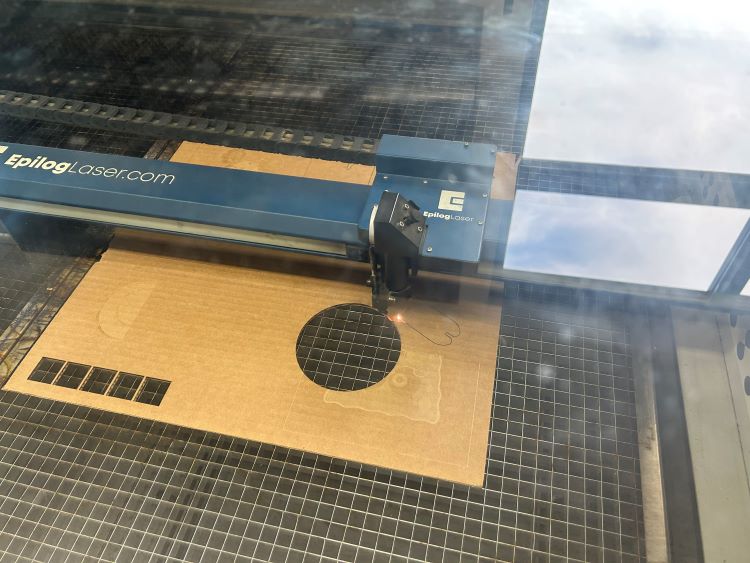
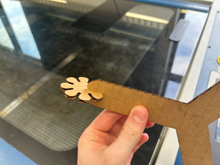
The pieces worked perfectly and fit together extremely nicely, both being secure yet possible to take out and not too hard to push together.
Kerf Conundrum
Just now, my group realized that we had done the calculations for the kerf of our laser cutter incorrectly. When we laser cut 1in squares to test, we used this formula to calculate kerf: (1 - sideLength) / 2, but the kerf subtracting on each side is only half of the total kerf because half of the kerf is on the other side of the cut out square, so the formula should have been simply 1 - sideLength. It turns out I should have been using the larger value of 0.0142in. This would have made the joint less tight as the lines would have been offset more, making the slots wider.
On a separate note, I know this value, and the old one, are both the average between cardboard and wood, but considering some of the potential experimental error when measuring the cardboard kerf, described on the group page, and for reusability of the same SVG files, I decided to stick with the joint value.
I actually really liked how the old value felt with the joint, so I could always change the slotWidthOffset parameter to match my mistaken kerf value. Even so, I still decided to test with the new kerf value, which I ended up using in the final design. I test more joint settings and clearances later on this page.
Push-Out Pieces
The Plan
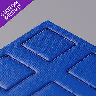
I also wanted to modify my design to where the pieces will stay in the cardboard until pushed out.
My first thought was a mechanism similar to this one where the vector would stop right before the pieces were completed.
Cuttle Scripting
I was having trouble when figuring out how to make little holes in a shape outline in Cuttle. I first played around with subtracting a very thing rectangle, but I ended up creating a rectangular hole, not cutting out a part of the path.
I then tried to use the Modfy > Dashed Line command, but I was dissatisfied with the results as I couldn't control the number of dashes without having a variable to represent the length of the outline of the object in the formula, which I wasn't able to obtain.
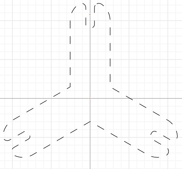
As I kept researching how to control the number of dashes, I came across this webpage which introduced me to the world of scripting in Cuttle. I explored the Random Dashed example project linked on the page which uses two Custom Modifiers written in JavaScript: Dashed Line and Random Dashed.
I knew these modifiers held the solution to my problem as the programmer was able to hand-control the dashes in the stroke through code. To view the source code, I duplicated the project and clicked the pencil icon next to the modifier on an object.
Fortunately, I am proficient in JavaScript and parsed through the code to understand how it modified the objects that represented objects in Cuttle. I also skimmed through the Scripting section of this tutorial to get an understanding of the framework around the code and how it interacts with Cuttle.
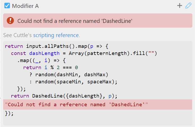
To test out these modifiers, I created a custom modifier in my own project using the Modify > New Modifier program and copied the code from the Random Dashed modifier in the example project, attaching it to the highest-level object of the ProngedConnector object.
return input.allPaths().map(p => {
  const dashLength = Array(patternLength).fill("")
    .map((_, i) => {
      return i % 2 === 0
        ? random(dashMin, dashMax)
        : random(spaceMin, spaceMax);
    });
  return DashedLine({dashLength}, p);
});
Yet, I recieved the following error.
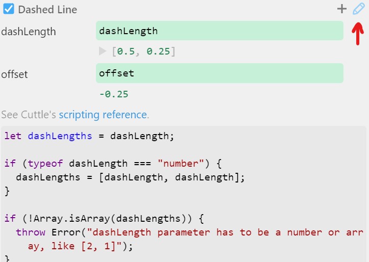
I determined that I needed to also add the Dashed Line custom modifier from the example project, so I created another new modifier, named it Dashed Line, copied the example code, then removed that modifier from the object (it still existed under the Modify dropdown).
let dashLengths = dashLength;

if (typeof dashLength === "number") {
  dashLengths = [dashLength, dashLength];
}

if (!Array.isArray(dashLengths)) {
  throw Error("dashLength parameter has to be a number or array, like [2, 1]");
}

// Double the array if it's not even, to make offset easier to work with
if (dashLengths.length % 2 !== 0) {
  dashLengths = dashLengths.concat(dashLengths);
}

const dashLengthsSum = dashLengths
  .reduce((dash, sum) => dash + sum, 0);

if (dashLengthsSum <= 0) {
  throw Error("Dash lengths need to add up to more than 0.");
};

const dashLengthsCount = dashLengths.length;

// This step won't be needed soon...
input.allCompoundPaths().forEach(cp => {
  cp.allPaths().forEach(p => {
    p.copyStyle(cp)
  });
});

const out = input.allPaths().map((path) => {
  const splitPath = [];
  const pathLength = path.length();

  if (pathLength / dashLengthsSum * dashLengthsCount > 10000) {
    throw Error("Too many dashes, try a bigger value in dashLength.");
  }

  let i = 0;
  let head = 0;
  // We want to start the dash pattern on or before the start of the path
  if (offset !== 0) {
    head = modulo(offset, dashLengthsSum) - dashLengthsSum;
  }
  while (head < pathLength) {
    const dash = dashLengths[i % dashLengthsCount];
    const space = dashLengths[(i+1) % dashLengthsCount];
    let dashStart = head;
    let dashEnd = head + dash;
    if (dashStart < 0) {
      dashStart = 0;
    }
    if (dashEnd > pathLength) {
      dashEnd = pathLength;
    }
    if (
      dashStart >= 0 && dashEnd >= 0 &&
      dashStart < pathLength && dashEnd <= pathLength &&
      dashStart < dashEnd
    ) {
      splitPath.push(
        path.slice(
          path.timeAtDistance(dashStart),
          path.timeAtDistance(dashEnd)
        )
      );
    }
    head += dash + space;
    i += 2;
  };
  // Merge last and first dash if needed
  if (path.closed) {
    const firstDash = splitPath[0];
    const firstAnchor = firstDash.anchors[0];
    const lastDash = splitPath[splitPath.length - 1];
    const lastAnchor = lastDash.anchors[lastDash.anchors.length - 1];
    if (
      firstAnchor.position.equals(lastAnchor.position)
    ) {
      const combinedDash = lastDash === firstDash
        ? Path.fromFragments([firstDash])
        : Path.fromFragments([lastDash, firstDash]);
      splitPath.pop();
      splitPath.splice(0, 1, combinedDash);
    }
  }
  const compoundPath = CompoundPath(splitPath);
  // Ignores fill
  if (path.stroke) {
    compoundPath.assignStroke(path.stroke);
  }
  return compoundPath;
});

return out;
Now I recieved this error.
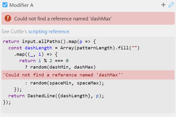
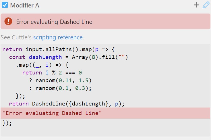
But this was an easy fix as instead of creating parameters, I just replaced their references with the values used in the example directly in the code. This is what the Modifier A code looks like now.
return input.allPaths().map(p => {
  const dashLength = Array(8).fill("")
    .map((_, i) => {
      return i % 2 === 0
        ? random(0.11, 1.5)
        : random(0.1, 0.3);
    });
  return DashedLine({dashLength}, p);
});
But yet another error!
This error took me a long time to figure out because I couldn't access the error message from the Dashed Line component. To try to figure out what was going on, I also added the Dashed Line modifier to the object (to the left of, or before, the Modifier A badge on the objetc), and I saw the following.
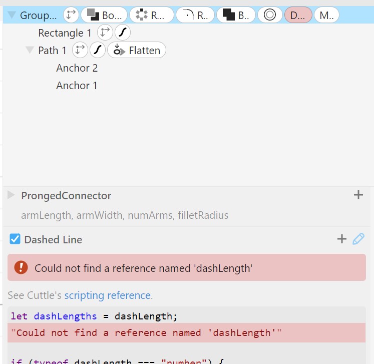
I found this strange, since the lsat line of the Modifier A script passed a JSON object with the variable dashLength to the Dashed Line script.
return DashedLine({dashLength}, p);
Note that {value} in JavaScript is shorthand for {value: value} where the key name is the same name as the variable itself.
I took a look at the example project and noticed that there was a parameter specific to the modifier called dashLength on top of passing it as an argument in the Random Dashed script. I couldn't find any reason as to why this was necessary in the Cuttle documentation, but it worked so I stuck with it. I encountered a similar error for the offset parameter and added this one, as well. I also had to set dashLength to a positive, non-zero integer to avoid another error. After deleting the Dashed Line modifier from the object, the Random Dashed script worked! I also played around with removing the randomness and the result was promising!
Now I had to adapt the code to fit my needs. I created the tabWidth and numTabs parameters to represent the width of the hole in the line and the number of holes, respectively. I first check if either of these are equal to or less than zero, and if so, throw and error. Reading through the Dashed Line code, I deduced that the argument in the Array() constructor represents the number of segments in the dashed line, so I wanted this to be numTabs*2, or one segment for every hole and one for every segment between holes. I learned from this line in the Dashed Line script that the length method of the Path type returns the number of anchors, or length, of the path, so I used this to define the variable of pathLength when looping through each path the modifier is applied to. I then changed the ternary operator in the return statement to either be
const pathLength = path.length();
if (tabWidth <= 0) throw Error("tabWidth shouldn't be <= 0");
if (numTabs <= 0) throw Error("numTabs shouldn't be <= 0")

return input.allPaths().map(p => {
  const pathLength = p.length();
  const dashLength = Array(numTabs*2).fill("")
    .map((_, i) => {
      return i % 2 === 0 ? pathLength / (numTabs*2) : tabWidth;
    });

   return DashedLine({dashLength}, p);
});
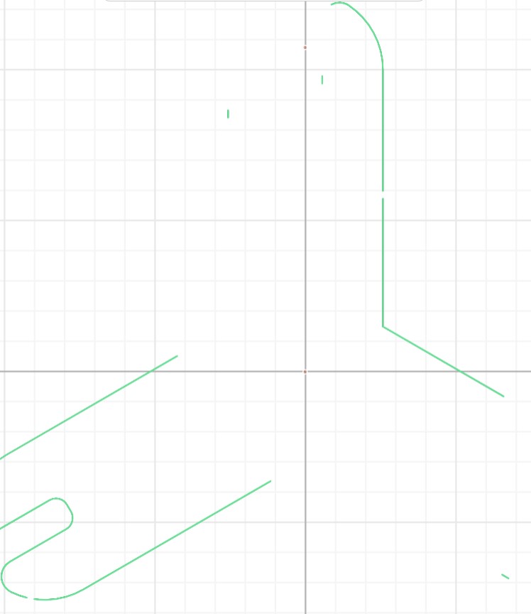
I realized I had two mistakes: the length of the segments between tabs should be pathLength / (numTabs*2) - tabWidth and for some reason the program was doubling the number of tabs. I'm not sure why, but I just changed Array(numTabs*2) to Array(numTabs). For some reason, this gave very strange results and wasn't successful.
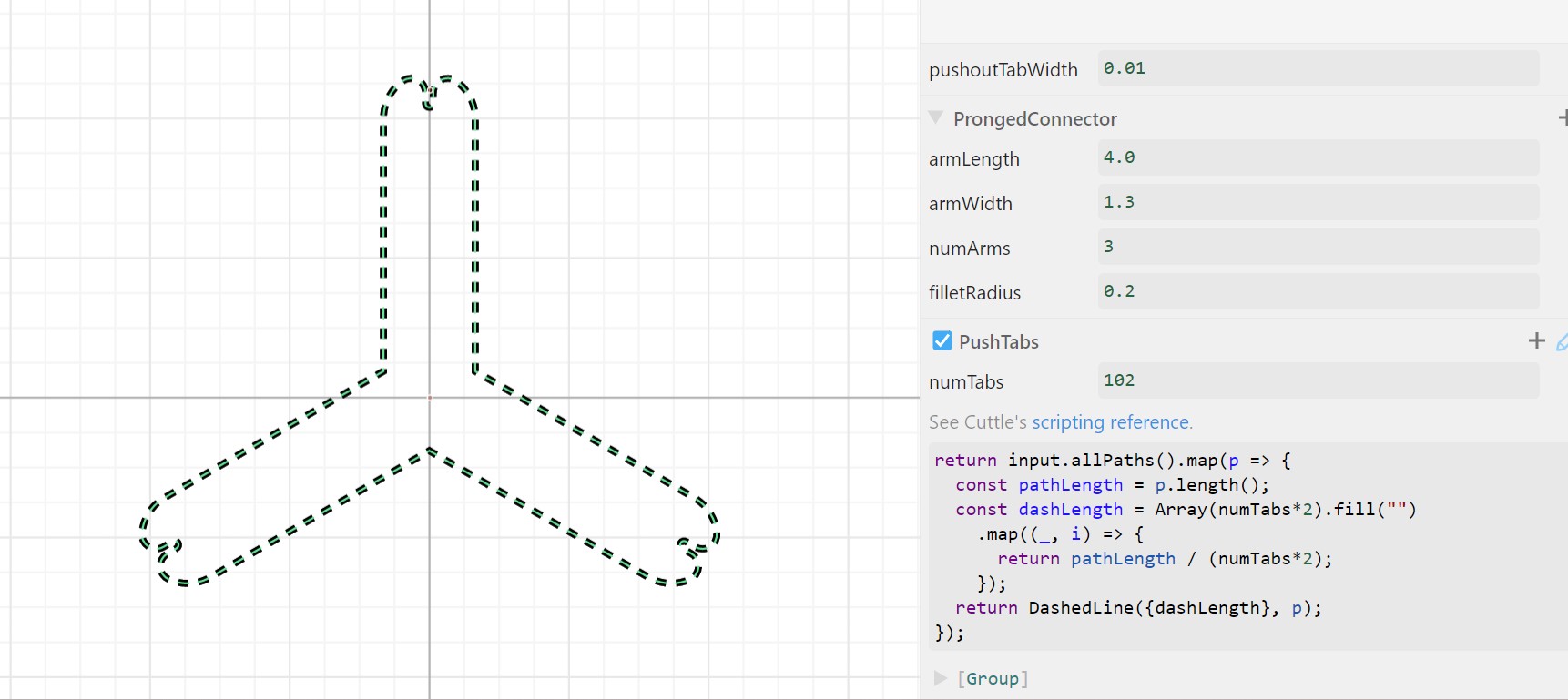
I instead tried to multiply the length value by two to half the number of segments, and this worked!
if (tabWidth <= 0) throw Error("tabWidth shouldn't be <= 0");
if (numTabs <= 0) throw Error("numTabs shouldn't be <= 0")

return input.allPaths().map(p => {
  const pathLength = p.length();
  const dashLength = Array(numTabs*2).fill("")
    .map((_, i) => {
      return i % 2 === 0 ? (pathLength / (numTabs*2)) - tabWidth : tabWidth;
    });

   return DashedLine({dashLength}, p);
});
I also noticed in the example for Dashed Line that a two-item array could also be the input value of dashLength, the first item representing the segment length and the second the tab length.
if (tabWidth <= 0) throw Error("tabWidth shouldn't be <= 0");
if (numTabs <= 0) throw Error("numTabs shouldn't be <= 0")

return input.allPaths().map(p => {
  const pathLength = p.length();
  /*const dashLength = Array(numTabs*2).fill("")
    .map((_, i) => {
      return i % 2 === 0 ? (pathLength / (numTabs*2)) - tabWidth : tabWidth;
    });*/
  const dashLength = [(pathLength / (numTabs*2)) - tabWidth, tabWidth];

   return DashedLine({dashLength}, p);
});
I also didn't want to have to create two custom modifiers if I ever decided to use this code in another project, so I combined the above code with the Dashed Line code to the following, final program.
if (tabWidth <= 0) throw Error("tabWidth shouldn't be <= 0");
if (numTabs <= 0) throw Error("numTabs shouldn't be <= 0")

return input.allPaths().map(p => {
  const pathLength = p.length()*2;
  const dashLength = [(pathLength / (numTabs*2))-tabWidth, tabWidth];

  let dashLengths = dashLength;

if (typeof dashLength === "number") {
  dashLengths = [dashLength, dashLength];
}

if (!Array.isArray(dashLengths)) {
  throw Error("dashLength parameter has to be a number or array, like [2, 1]");
}

// Double the array if it's not even, to make offset easier to work with
if (dashLengths.length % 2 !== 0) {
  dashLengths = dashLengths.concat(dashLengths);
}

const dashLengthsSum = dashLengths
  .reduce((dash, sum) => dash + sum, 0);

if (dashLengthsSum <= 0) {
  throw Error("Dash lengths need to add up to more than 0.");
};

const dashLengthsCount = dashLengths.length;

// This step won't be needed soon...
input.allCompoundPaths().forEach(cp => {
  cp.allPaths().forEach(p => {
    p.copyStyle(cp)
  });
});

const out = input.allPaths().map((path) => {
  const splitPath = [];
  const pathLength = path.length();

  if (pathLength / dashLengthsSum * dashLengthsCount > 10000) {
    throw Error("Too many dashes, try a bigger value in dashLength.");
  }

  let i = 0;
  let head = 0;
  // We want to start the dash pattern on or before the start of the path
  if (offset !== 0) {
    head = modulo(offset, dashLengthsSum) - dashLengthsSum;
  }
  while (head < pathLength) {
    const dash = dashLengths[i % dashLengthsCount];
    const space = dashLengths[(i+1) % dashLengthsCount];
    let dashStart = head;
    let dashEnd = head + dash;
    if (dashStart < 0) {
      dashStart = 0;
    }
    if (dashEnd > pathLength) {
      dashEnd = pathLength;
    }
    if (
      dashStart >= 0 && dashEnd >= 0 &&
      dashStart < pathLength && dashEnd <= pathLength &&
      dashStart < dashEnd
    ) {
      splitPath.push(
        path.slice(
          path.timeAtDistance(dashStart),
          path.timeAtDistance(dashEnd)
        )
      );
    }
    head += dash + space;
    i += 2;
  };
  // Merge last and first dash if needed
  if (path.closed) {
    const firstDash = splitPath[0];
    const firstAnchor = firstDash.anchors[0];
    const lastDash = splitPath[splitPath.length - 1];
    const lastAnchor = lastDash.anchors[lastDash.anchors.length - 1];
    if (
      firstAnchor.position.equals(lastAnchor.position)
    ) {
      const combinedDash = lastDash === firstDash
        ? Path.fromFragments([firstDash])
        : Path.fromFragments([lastDash, firstDash]);
      splitPath.pop();
      splitPath.splice(0, 1, combinedDash);
    }
  }
  const compoundPath = CompoundPath(splitPath);
  // Ignores fill
  if (path.stroke) {
    compoundPath.assignStroke(path.stroke);
  }
  return compoundPath;
});

return out;
});
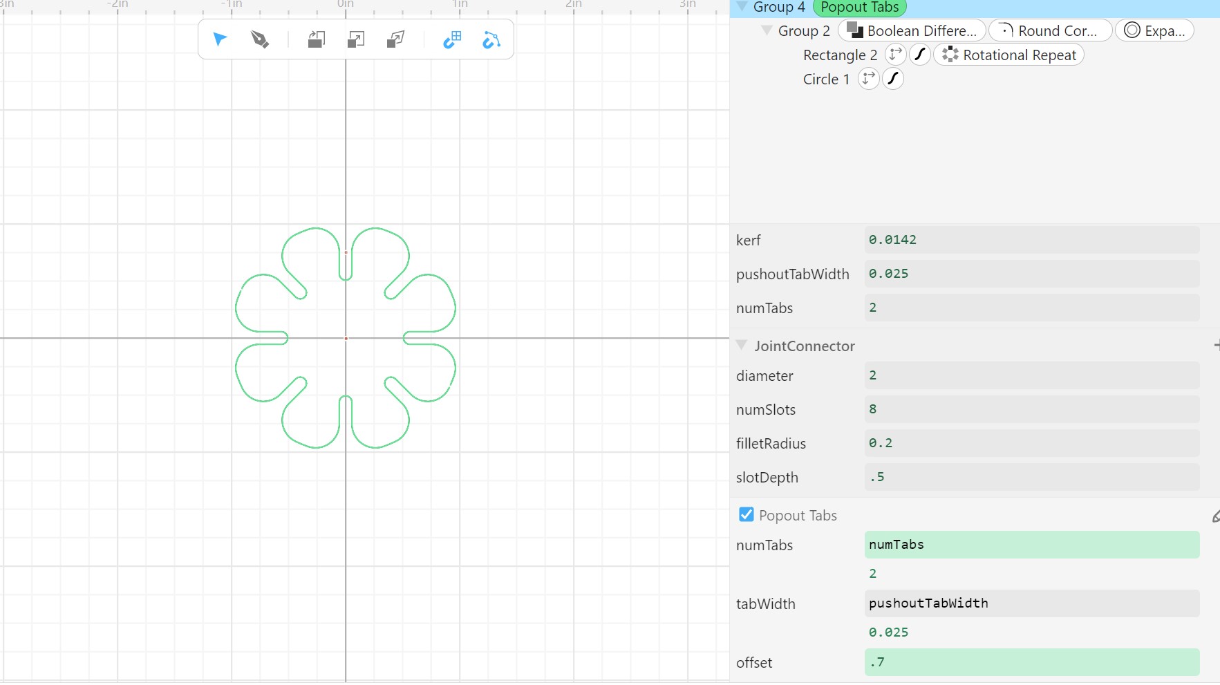
I also tried moving the modifier to before the rotational repeat was applied to get the effect to be uniform across branches, but this didn't easily work and I decided that it doesn't make a difference in the end. I also renamed the modifier to Popout Tabs. Another strange detail I noticed is that I cannot pass component-specific parameters into my custom modifier, only project-wide parameters. As I'm searching for bugs with Cuttle, it is very hard to find answers easily online and not many results come up related to Cuttle, so I decided to leave this issue alone.
Testing Parameters
Designing Tests
Tabs
To test different parameters, I added a text object under my ProngedConnector and edited the formula of the text to "T"+numTabsPronged+"W"+pushoutTabWidth. I also set the align to center, the x-position to 0, the y-position to 1.7 and the scale to Vec(1,1). I unchecked the hairline option under stroke and set the width to 0.025.
Here is a link to the design file for testing the tabs!
More Slot Testing
I also made another batch of test files with different offset values for the slot width and fillet radius with the naming convention "F"+filletRadius+"O"+slotWidthOffset. I also temporarily disabled the Popout Tabs custom modifier. I had to print out two of each of these so I could test them fitting together. I decided it would be wasteful to print out two of each of the combinations of settings for the three-proged pieces, so I created this Cuttle design that would only print out two, disconnected arms. I ended up having to move the two overlapping lines apart in CorelDRAW before laser cutting so the laser wouldn't vector cut the same path twice, risking a fire.
Cutting The Tests
Over the weekend when I worked on this section of the project, I had access to a Glowforge laser cutter which is cloud-based in terms of uploading files, but in the interface I could only uplaod one SVG at a time. To solve this, I uploaded all of the SVGs at once to Inkscape then uploaded the SVG generated in Inkscape (Inkscape automatically saves to SVG) to Glowforge. Then I noticed I couldn't upload mulitple SVGs at once to Inkscape through the File > Import tool, but I learned from this article that I could drag multiple files directly from File Explorer into Inkscape, then it worked.
When using Glorforge, I learned that unlike CorelDRAW with Fusion Pro laser cutters, stroke width doesn't differentiate parts of a design, but colors. To solve this, I changed all of the text to have a red stroke in Inkscape, and then I was able to change what was rastered and what was vectored on the Glorforge website.
Test Results
Here are all of the different settings that I tested for tabs:
| 1 Tab | 2 Tabs | 3 Tabs | 4 Tabs | 5 Tabs | 8 Tabs | |
|---|---|---|---|---|---|---|
| 0.05in Width | ✔️ | ✔️ | ✔️ | ✔️ | ✔️ | ✔️ |
| 0.025in Width | ✔️ | ✔️ | ✔️ | ✔️ | ✔️ | ✔️ |
| 0.01in Width | ❌ | ❌ | ✔️ | ❌ | ✔️ | ✔️ |
| 0.0175in Width | ❌ | ❌ | ❌ | ❌ | ✔️ | ❌ |
Here are all of the different settings I planned to test for joints:
| 0.0in Fillet | 0.05in Fillet | 0.10in Fillet | 0.15in Fillet | |
|---|---|---|---|---|
| -0.0071in Offset | ✔️ | ✔️ | ✔️ | ✔️ |
| 0.0in Offset | ✔️ | ✔️ | ✔️ | ✔️ |
| 0.01in Offset | ✔️ | ✔️ | ✔️ | ✔️ |
In the end, I did test all of the possible tab settings, but when I cut out the fillet and offset settings, I made the pieces too close together and accidentally vectored one of the words instead of rastering, so the cardboard started to catch on fire. Thankfully, this went out on its own, but I stopped the cut. Actually one of the first three settings I tested, 0.2in fillet and 0in offset, worked exremely well, both easy to insert and fairly sturdy, yet stil able to remove, so I stopped testing and stuck with that setting!
Taking Into Account Group Joint Testing
The group joint testing results fell very closely in line with mine. See my group reflection page for more details.
Power Modification
I also wanted tried using a slightly lower power than the recommended for vector cutting to achieve the same effect, but I didn't have time to get to this extra experiment this week. Maybe I'll come back to it in the future.
Final Fixes
I moved the slotDepth project-wide parameter to two separate component-specific parameters with values of .75 and .5 for the ProngedConnector and JointConnector component, repsectively. Also, on the JointConnector component, I gave my custom Popout Tabs modifier an offset of 0.7 so that rotational pressure wouldn't be but on the prongs when pushed out of the cardboard.
I also grouped the highest-level object on each component and applied the Modify > Tile Repeat tool. For the ProngedConnector component, I made displacement1 and displacmeent2 variables Vec(armLength*2 + armWidth/2, 0) and Vec(0, armLength*2-(armLength-armWidth*2)), respectively. I found that these values worked nicely without overlap for all different component and project parameter values. For the JointConnector, I made the values Vec(diameter+tileOffset, 0) and Vec(0, diameter+tileOffset). I also created the component-specific tileOffset parameter and set it to 0.1.
Cutting The Final Kit
I downloaded the SVG on the computer connected to the laser cutter, imported it into a new CorelDRAW file, and set all the lines to hairline. I also created a hairline rectangle around all of the pieces. I then set it to cut, but the laser cutter cut out the rectangle first which then fell down slightly and made the rest of the cut at a different focus, so I stopped the job.
I then just uploaded two separate jobs (one for the pieces and one for the outline) and ran them seperately. This worked well, and I did the same for the other piece.
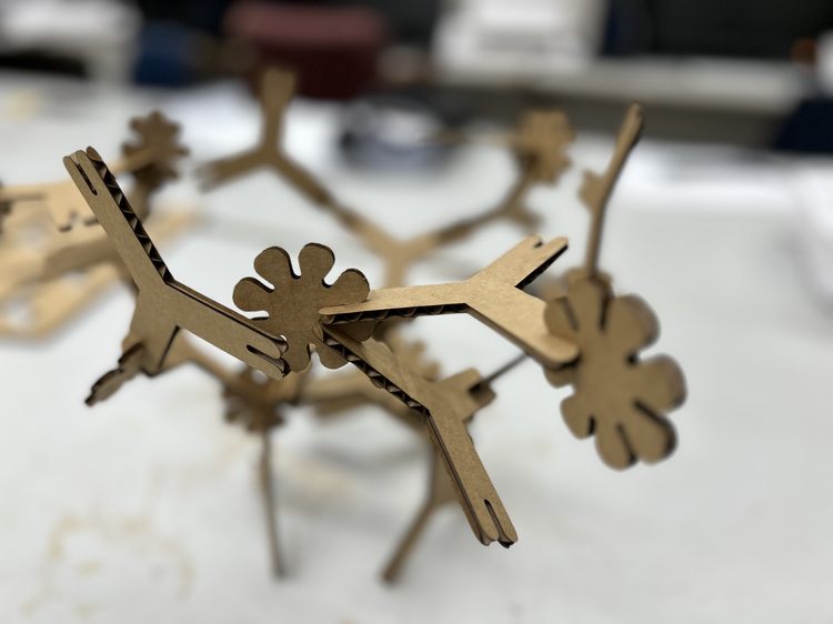
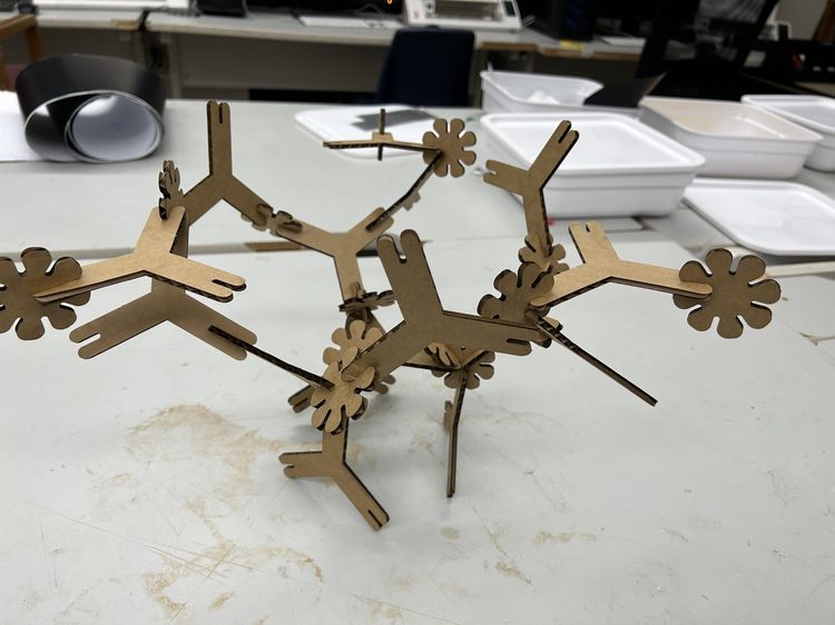
Conclusion And Hero Shots
The tabs worked well for the most part, other than that one of the pronged connector's tabs did not hold and the piece fell out when I picked up the cardboard. I then infered that the Epilog Pro laser's different features than the Glowforge laser made the tabs cut less precisely and consistently. Even so, I was happy with the final outcome! Here is the hero shot of something I built with my pieces.