ATtiny412
Why?
The ATtiny412 is a microcontroller, like an Arduino, that's far cheaper and has less features. It's a far more efficient solution for projects that can be controlled through less-complex processes. This is a workflow I created for programming an ATtiny412 chip using an Arduino.
Arduino As A Programmer
jtag2updi
I used the jtag2updi protocol to transfer code to the ATtiny412 through the Arduino as a programmer. First, I send a program from the Arduino IDE to the Arduino Uno, and when the Arduino runs that program, it begins to act as a programmer. That means future programs it receives will not be run on the Arduino itself, but instead passed along to the ATtiny412 chip.
Board Type
When trying to implement this, I originally encountered many difficulties surrounding the compiling and uploading process, but when I opened the Tools menu of the Arduino IDE, I realized that, when uploading the jtag program, I needed to have Arduino Uno selected as the board, not ATtiny412, because jtag is meant to be run on the Arduino.
After correcting this, I encountered error messages surrounding the COM Ports, leading me to realize that I had also selected the incorrect COM port.
COM Port
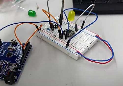
After correcting the COM port, the program uploaded successfull*y. Then, I opened the blink example program in the Arduino IDE, but this time I changed the board to ATtiny412/... before uploading. I also connected the 5V and GND of the Arduino to the Vcc and GND of the ATtiny412, respectively, as well as connecting Pin 6 of the Arduino Uno to the UPDI pin of the ATtiny412.
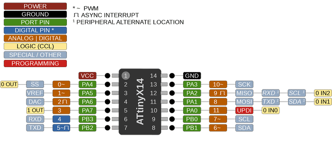
This time it worked! After connecting an LED to the output pin (here is a diagram with the software pins that correspond to the hardware on the ATtiny412), a 330 ohm resistor, and ground, it blinked!
Additional Adjustments
Blink Timing
I also adjusted the parameters of the delay() functions in the code to modify the milliseconds for which the LED stayed on and off.
void setup() {
  pinMode(2, OUTPUT);
}

void loop() {
  digitalWrite(2, HIGH);
  delay(100);
  digitalWrite(2, LOW);
  delay(75);
}
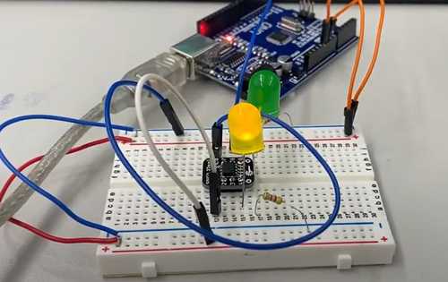
Multiple LEDs
Next, I worked on implementing two different LEDs. This was not very much of a challenge – I simply added another output pin in the code and hooked another LED and resistor to the corresponding pin on the ATtiny412.
void setup() {
  for (int i = 2; i <=3; ++i) pinMode(i, OUTPUT);
}

void loop() {
  digitalWrite(2, HIGH);
  delay(1000);
  digitalWrite(2, LOW);
  digitalWrite(3, HIGH);
  delay(1000);
  digitalWrite(3, LOW);
  digitalWrite(2, HIGH);
  delay(100);
  digitalWrite(2, LOW);
  digitalWrite(3, HIGH);
  delay(100);
  digitalWrite(3, LOW);
}
Analog Ouptut
Afterwards, I challenged myself to use the digital output pins on the ATtiny412 to simulate an analog output, or in other words, manually implementing PWM. The program below uses a loop where, each time the loop runs, it increases the proportion of time in a fixed interval that an LED is on.
For example, the first time might be 5 milliseconds with the LED on for 5% of the 5 milliseconds. Then, the next iteration the LED might be on for 10% of the 5 milliseconds. I made variables that can be adjusted by anyone running the program to adjust the ratios.
int ratio_interval = 100;
void setup() {
  for (int i = 2; i <= 3; ++i) pinMode(i, OUTPUT);
}

void loop() {
  for (int i = 2; i <= 3; ++i) {
    for (int ratio = 0; ratio <= 100; ++ratio) {
        for (int j = 0; j < ratio_interval; ++j) {
        digitalWrite(i, HIGH);
        delay(ratio/ratio_interval);
        digitalWrite(i, LOW);
        delay((100-ratio)/ratio_interval);
      }
    }
    for (int ratio = 100; ratio >= 0; --ratio) {
        for (int j = 0; j < ratio_interval; ++j) {
        digitalWrite(i, HIGH);
        delay(ratio/ratio_interval);
        digitalWrite(i, LOW);
        delay((100-ratio)/ratio_interval);
      }
    }
  }
}
Input Button
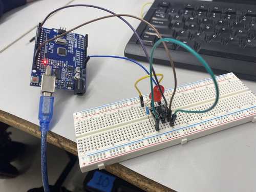
Finally, I tried to use a button to control the LED through the ATtiny412 chip. The goal with the mini-project is to make the LED turn on when I click the button, but to do it through the chip instead of just connecting a battery, resistor, and LED (I wouldn't even need a microcontroller!). So we want to set it up where:
- The button controls a signal being sent into (
INPUT) the chip - When the chip receives that signal, it sends a different signal (
OUTPUT) to turn on an LED.
So the first thing I did in the code was set up one pin as an input and one as an output — we do this in the setup() function. For example:
pinMode(2, OUTPUT);
pinMode(3, INPUT);
Then, I hooked the 5V coming out of the Arduino so that it only connects to the INPUT pin when the button is pressed. The circuit will look like 5V ——— *button* ———— *input pin*.
Now, in the loop() function, I can read voltage coming into the INPUT pin. If the button is pressed (the circuit is closed), digitalRead(*the input pin*) will equal HIGH, and if it isn’t it will equal LOW.
Then, I needed to do something with that information — I made an if/else statement where if the INPUT pin is HIGH, then it sends a signal to the OUTPUT pin.
But, it turns out, I didn't even need the if/else statement – the return value of digitalRead() is HIGH or LOW, and the parameters of the digitalWrite() function are the pin number and the state it should write to that pin (HIGH or LOW). Therefore, I can simplify the code to simply:
digitalWrite(*output pin number*, digitalRead(*input pin number*));
Finally, I should probably connect the OUTPUT pin to something... that something is the LED (and a resistor as to not fry the LED).
So the circuit looks like *output pin* ———— LED ——- resistor ——— ground.
#define BUTTON_PIN 3
#define OUTPUT_LED_PIN 2
void setup() {
  pinMode(OUTPUT_LED_PIN, OUTPUT);
  pinMode(BUTTON_PIN, INPUT);
}

void loop() {
  digitalWrite(OUTPUT_LED_PIN, digitalRead(BUTTON_PIN));
}