Milling A Circuit
Bantam Tools
Using the Bantam Tools software, I opened two files, edge cuts and the ciruit itself.

Following the workflow, I configured the settings for different bits and positioned the files so that they would not overlap. Then, I calibrated the Z-axis of the machine and set it to cut.
Changing Bits
Once it had completed milling the circuit, I used the vacuum to remove the debris, put foam under the bit in case I dropped it, and changed the bit to a 1/32" instead of a 1/64".

Finishing The Cut
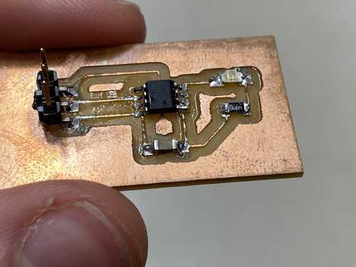
I continued the milling and cut the outline of the board. Once again I used the vacuum to remove the debris and removed the board from the machine. One detail that I had to pay special attention to was when to position the metal 'holding piece' on the copper and when to take it off – it is necessary to held the board steady with the metal piece when the machine is calibrating, but it must be taken off the board once the milling begins, otherwise it would get in the way of the actual cutting.

Second Pass
Also, when I was cutting the outline of the board, the first pass didn’t actually touch the metal, so I stopped the machine, but I soon realized that it only started cutting the material on the second pass.

Code And Testing
Here is the code I used to test my project.
void setup() {
  pinMode(2, OUTPUT);
}

void loop() {
  digitalWrite(2, LOW); // LOW – creates potential difference – LED is actually ON
  delay(1000);
  digitalWrite(2, HIGH);
  delay(1000);
}
LEDs require a difference in voltage to turn on. This circuit was designed in suhc a way that Vcc is always being put into the LED, and the ATtiny412 pin changes the signal on the other side of the LED. Therefore, when the pin is HIGH, the LED is off since there's on difference in voltage, but when the pin is LOW, the input to the LED is HIGH so the LED turns on. Because of this concept, I abstracted my code to be easily understandable.
void LED_ON() { digitalWrite(2, LOW); } // abstracted – LOW means ON – increased readability
void LED_OFF() { digitalWrite(2, HIGH); } // same as LED_ON() but vice-versa

void setup() {
  pinMode(2, OUTPUT);
}

void loop() {
  LED_ON();
  delay(1000);
  LED_OFF();
  delay(1000);
}