Cuttle
Getting Started
To learn the basics of Cuttle, I completed the first two Getting Started tutorials as well as the Intro to Parameters tutorial on this page. They were very straightforward, and I didn't run into any trouble.
Designing A Case
The Plan
I'll try to use Cuttle to create a case for the display I'll use in my final project. This website has dimensions for the outline of the component as well as the actual screen dimensions. I wanted to make a case similar to this laser-cut one.
Using Cuttle
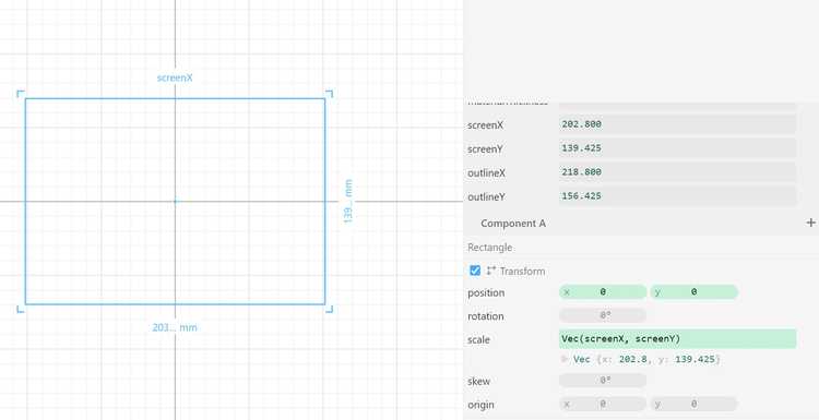
To get started, I opened a new project in Cuttle. I changed the dimensions to milimeters and created several project parameters: materialThickness, screenX, screenY, outlineX, outlineY. For now, I set materialThickness to the thickness of the screen (1.15mm). I then dragged in a rectangle, clicked on the width, and typed in screenX, but this didn't work. I realized the problem is that I needed to type the dimension into the inspector - it turns out I was accidentaly editing the name of the shape. After doing so, it worked and I'm able to update the rectangle by changing the parameters.
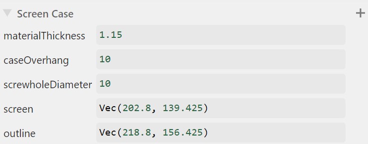
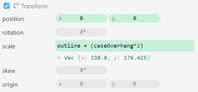
I did the same for another rectangle with the outline dimensions. I then renamed the component E-Ink Display and created a new component called Back. I also created another project parameters called caseOverhand that represents the length that the case will extend beyond the display on each side, and I set it to 10mm for now. I then created a rectangle and made set the scale variable to Vec(outlineX+(caseOverhang*2), outlineY+(caseOverhang*2)). I multiplied the caseOverhang by two so that it extends the full length of the parameter over every side of the display.
Next, I created a new component named Center. I created the component parameter centerTolerance and set it to 0.1mm. This parameter will represents the amount larger the center piece will be than the display in each dimension. I dragged in an instance of the Back component and created another rectangle. I set the dimensions to the outline parameters added to the tolerance parameter, except this time, I didn't double it because this parameter represents the total tolerance across each dimension, not each side of the piece. So the formula for the rectangle's scale looks like this: Vec(outlineX+toleranceCenter, outlineY+toleranceCenter).
I created a third component name Front. I dragged in another instance of the Back component and created another rectangle. I set this rectangle's dimensions to the dimensions of the screen of the display, meaning that it would cover the outline beyond the screen, holding the device in place, while still securing the display.
I realized that I could set a parameter to be a vector, so I changed all of the parameters that had an x and y component to one parameter that was a vector, then changed the scale values for the different objects to simply be that parameter - this really helped me clean up my project.
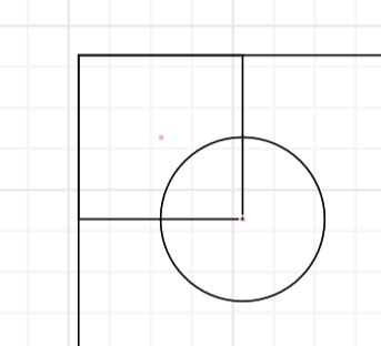
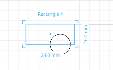
The next step was to make screw holes. Unliked sketches in Fusion 360 where I was able to simply define a dimension distance between a circle and a line, I had to make another rectangle anchored to the corner of the Back component then anchor a circle to the bottom corner of the smaller rectangle. Then I could turn the stroke off of the rectangle.
I realized that I could also use the same parameters that I used to define the rectangle, for example, making the x position of the circle -outlineX/2 + screwHoleDiameter + offset, but I decided it would be more elegant and readible to use the rectangle method. Yet when I adjusted the dimensions of the rectangle, its position didn't update.
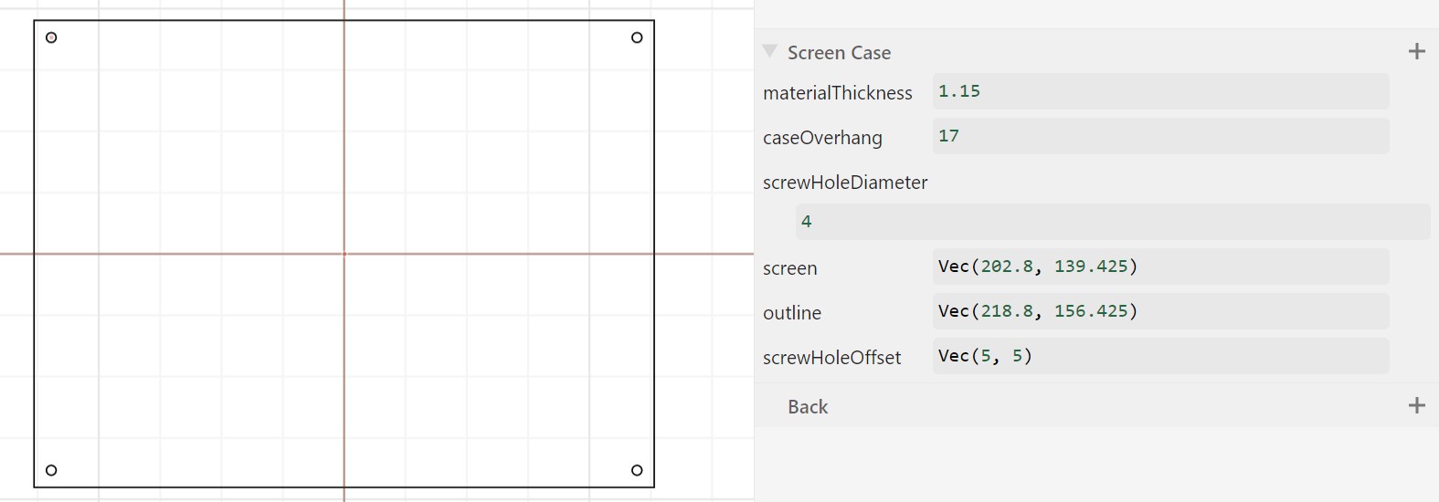
So I decided to go back to the other method. I set the position variable to -(outline/2 + caseOverhang) + screwHoleOffset + screwHoleDiameter/2 and the screwHoleOffset project parameter to Vec(5, 5) temporarily. Because I added screwHoleDiameter/2 to the position, the offset represents the distance between the border of the case and the outside of the circle, not its center.
I then added two mirror repeats to the circle, one along the x-axis and the other along the y-axis, and I had four screw holes! Because I imported the Back component into the other two components, the screw holes also updated on the other components!
Now I actually had to figure out how big to make the screw holes. Based on this website I learned the type of screw I needed is called a hex bolt. This page taught me the naming conventions for different hex bolts.
I had no idea what nominal diameter meant, so I looked it up and found that page two of this packet explains it represents a diameter in between the screw head and the width of the fastener i.e. the diameter that the screw whole should be!
I adjusted the screwHoleDiameter parameter to be 4mm and calculated that the length of the screw must be at least three times the material thickness (1.15mm * 3 = 3.45mm), so I decided on a M4x4 screw so there would be room for the hex nut.
Here is a link to the final design!
I also understand that I may still have to edit parts of the design for connecting electronics, but for a rough design my product is satisfactory.