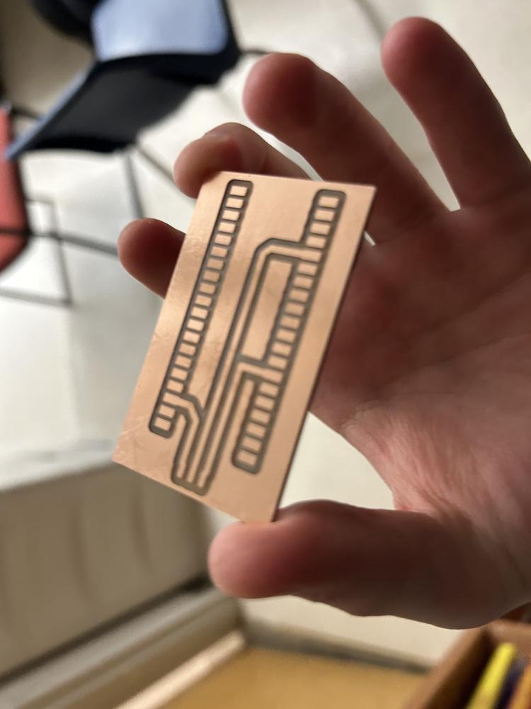
Milling The Board
Moving On
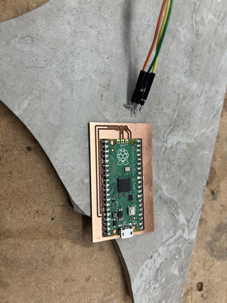
I decided to move on from the e-paper display for right now to focus on the servo and come back to the display later. I realized that the footprint for the SLIDE-SWITCH component in the fab library had the same SMD pads as I needed for three headers pins.
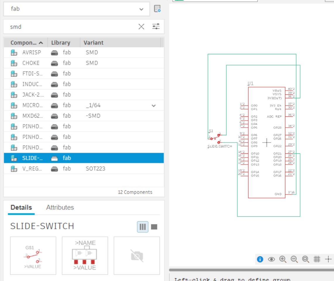
When routing I realized that there were holes in the slide-switch footprint but I simply designed my routes around them and will simply not mill them when I cut out my board.
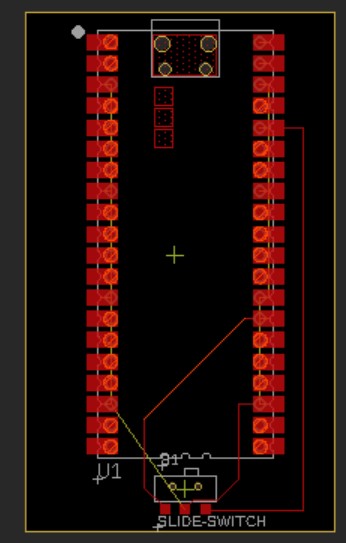
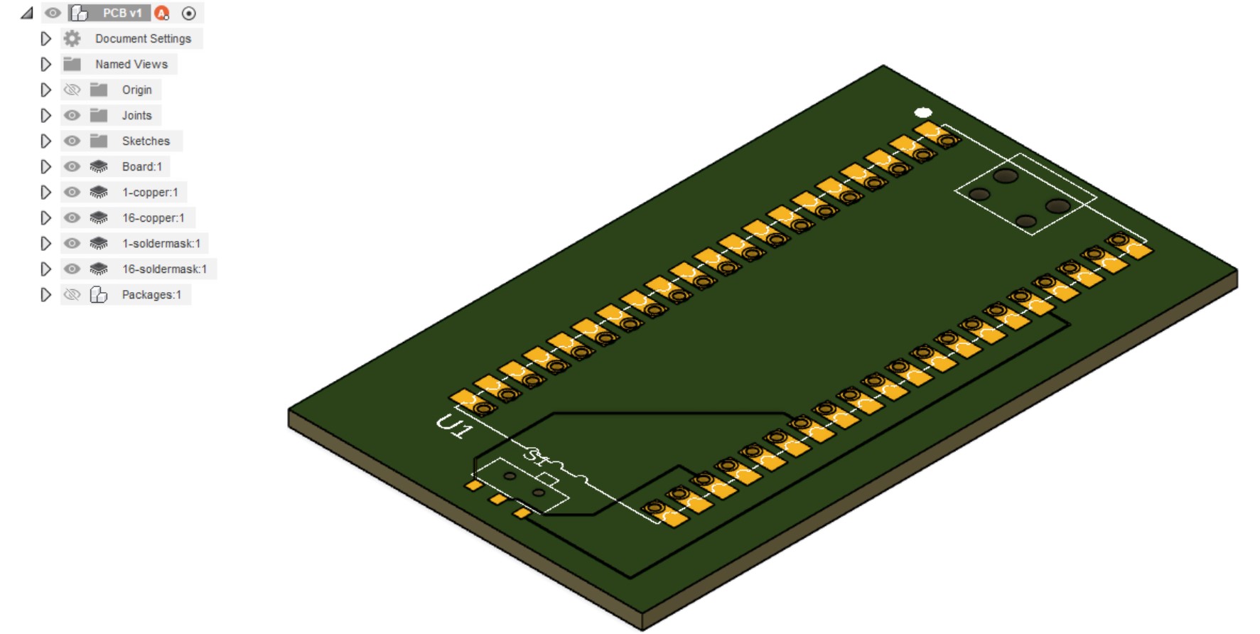
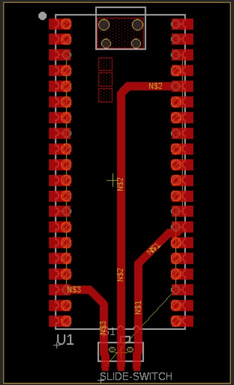
I was going to mill this board on the Genmitsu 3020-Pro Max milling machine, so I went to the Manufacturing workspace and created a new Setup. I selected a boxpoint on the top of the stock to where the x and y axes were hugging the stock. I selected all the traces and the top face of the board to be the Model, changed the Stock Top Offset to 0mm.
I went back and made the traces larger in the layout then made sure to deselect Solder Masks after I pressed Push to 3D PCB.
I then created a 2D Contour. When I selected the tool, I went to Milling Tools (Metric) and copied the smallest Flat Endmill I could find (3mm Flat Endmill). I then copied and pasted it into my Local > Library tools and right-clicked it and selected Edit tool. I changed the Description to 0.8mm Flat Endmill, Diameter to 0.8mm in the Cutter menu, Spindle speed to 12000 rpm in the Cutting data menu, Cutting feedrate to 100 mm/min in the same menu, and Plunge feedrate to 100 mm/min in the same menu.I then pressed the blue Accept button. I selected the new tool and set the Coolant setting to Disabled. Then for the Contour Selection I pressed the Chain icon and selected one of the traces. I repeated this for the top outline of every trace I wanted milled, which took a fairly large amount of time.
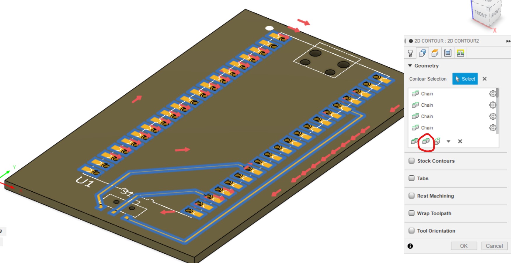
Next, under Top Height I set Offset to 0mm. I checked the Multiple Depths option (scroll down under the Passes menu) and set Maximum Roughing Stepdown to 0.4mm. I then pressed OK and activated the 2D Contour tool again. I selected the bottom outline of the board and used all the same other settings as the previous contour.
As I zoomed in I noticed that there were no blue lines around the second and third pads of the slide-switch component so I had to go back to the layout editor, decrease the DRC rules for minimum distance between a pad and a wire, then move the middle route in between the two switch holes. I also made all of the traces thicker. I then Pushed to 3D PCB again and made sure to uncheck Solder Mask. I got errors under the 2D Contour, so to recalculate I
Finally I right-clicked the previously-created Setup in the hierarchy and pressed Post Process. I made sure Post was set to Grbl / grbl and pressed Post.
The milling process was very smooth! I moved the z-axis high and zeroed it, then pressed Send to do an air cut. Everything looked OK so I moved the z-axis down until a piece of paper couldn't move in between the copper and the mill then zeroes the z-axis and moved the bit higher. I moved the x and y axes to the bottom left corner of the copper and zeroed them, as well. Then I pressed Reset and Send, and it worked! I occasionally vaccumed throughout the milling process.
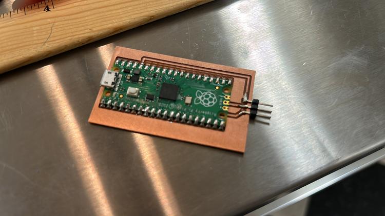
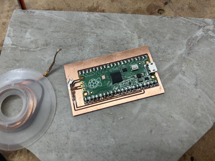
Here's the result after rinsing in water!

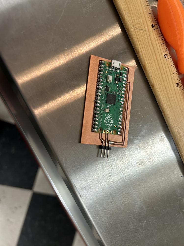
The soldering process was very smooth.
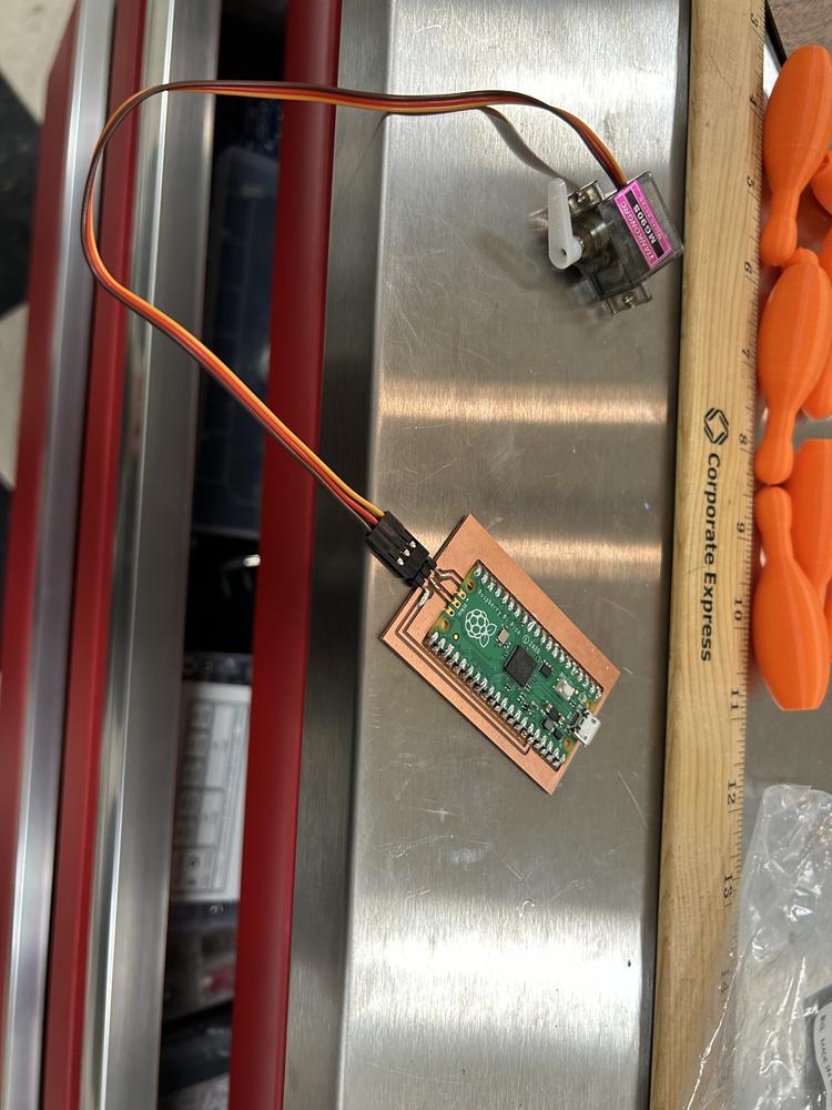
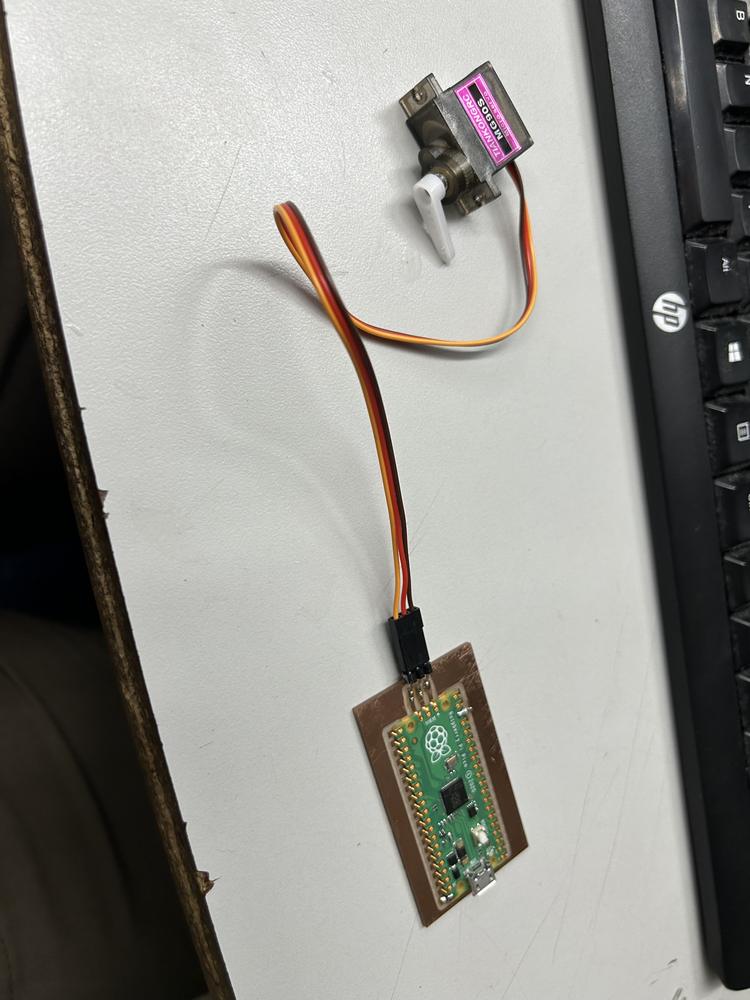
Unfortunately I realized that the order of the wires didn't match up with the servo so connecting it directly like this wouldn't work - I'll correct this in the next iteration of the design. For now I'll connect the servo like this.
The next day when I took the board out of my bag to test I noticed the traces ripped! These were thinner than other traces I'd milled so that might be why.
I tried resoldering with a lot of solder to reach what was left of the traces, but this failed.

I then tried to desolder mistakes and failed again - I needed to make a new board.
Redesigning Again
Just to be sure everything will work OK I made the traces' width 50mil.
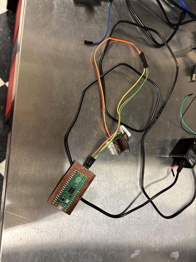
I milled the board, deburred it, washed it in soap and water, soldered it (very few connections to the pico so I could always unsolder if needed), and connected it to a servo motor. The only learning I had was that when I install a new tool I have to select the new tool button in the Bantam software then re-zero it. Also, I'd originally tried to only solder the corners and test the conections, but even though the other legs were touching, they weren't connected, so I soldered all of the legs that were connected to pin headers.

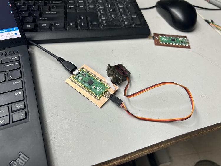
I tried plugging the board into my computer and nothing happened! I became very worried that I wasted another Pico, but tried a different chord, and it worked! I installed MicroPython using Thonny then ran the code from this website to operate a servo motor (I modified it to use GPIO 21). I copied and pasted both files into Thonny then saved them in the base directory of the Pico.
servo.py
from machine import Pin, PWM


class Servo:
    """ A simple class for controlling a 9g servo with the Raspberry Pi Pico.

    Attributes:

        minVal: An integer denoting the minimum duty value for the servo motor.

        maxVal: An integer denoting the maximum duty value for the servo motor.

    """

    def __init__(self, pin: int or Pin or PWM, minVal=2500, maxVal=7500):
        """ Creates a new Servo Object.

        args:

            pin (int or machine.Pin or machine.PWM): Either an integer denoting the number of the GPIO pin or an already constructed Pin or PWM object that is connected to the servo.

            minVal (int): Optional, denotes the minimum duty value to be used for this servo.

            maxVal (int): Optional, denotes the maximum duty value to be used for this servo.

        """

        if isinstance(pin, int):
            pin = Pin(pin, Pin.OUT)
        if isinstance(pin, Pin):
            self.__pwm = PWM(pin)
        if isinstance(pin, PWM):
            self.__pwm = pin
        self.__pwm.freq(50)
        self.minVal = minVal
        self.maxVal = maxVal

    def deinit(self):
        """ Deinitializes the underlying PWM object.

        """
        self.__pwm.deinit()

    def goto(self, value: int):
        """ Moves the servo to the specified position.

        args:

            value (int): The position to move to, represented by a value from 0 to 1024 (inclusive).

        """
        if value < 0:
            value = 0
        if value > 1024:
            value = 1024
        delta = self.maxVal-self.minVal
        target = int(self.minVal + ((value / 1024) * delta))
        self.__pwm.duty_u16(target)

    def middle(self):
        """ Moves the servo to the middle.
        """
        self.goto(512)

    def free(self):
        """ Allows the servo to be moved freely.
        """
        self.__pwm.duty_u16(0)
main.py
import utime
from servo import Servo

s1 = Servo(21)       # Servo pin is connected to GP21

def servo_Map(x, in_min, in_max, out_min, out_max):
    return (x - in_min) * (out_max - out_min) / (in_max - in_min) + out_min

def servo_Angle(angle):
    if angle < 0:
        angle = 0
    if angle > 180:
        angle = 180
    s1.goto(round(servo_Map(angle,0,180,0,1024))) # Convert range value to angle value

if __name__ == '__main__':
    while True:
        print("Turn left ...")
        for i in range(0,180,10):
            servo_Angle(i)
            utime.sleep(0.05)
        print("Turn right ...")
        for i in range(180,0,-10):
            servo_Angle(i)
            utime.sleep(0.05)
It worked! However, the servo movement was very jittery. To make sure this was a software problem and not a hardware problem, I modified main.py, and this reduced the jitteriness!
import utime
from servo import Servo

s1 = Servo(21)       # Servo pin is connected to GP21

def servo_Map(x, in_min, in_max, out_min, out_max):
    return (x - in_min) * (out_max - out_min) / (in_max - in_min) + out_min

def servo_Angle(angle):
    if angle < 0:
        angle = 0
    if angle > 180:
        angle = 180
    s1.goto(round(servo_Map(angle,0,180,0,1024))) # Convert range value to angle value

if __name__ == '__main__':
    while True:
        print("Turn left ...")
        for i in range(0,180,1):
            servo_Angle(i)
            utime.sleep(0.001)
        print("Turn right ...")
        for i in range(180,0,-10):
            servo_Angle(i)
            utime.sleep(0.001)
I tried making it even more smooth, but the servo wouldn't turn 180 deg, which I suspect is because 0.001sec is too short of a time for the servo to turn.
I modified the code to the following to test a functionality more similar to what I'll actually use.
import utime
from servo import Servo

s1 = Servo(21)       # Servo pin is connected to GP21

def servo_Map(x, in_min, in_max, out_min, out_max):
    return (x - in_min) * (out_max - out_min) / (in_max - in_min) + out_min

def servo_Angle(angle):
    if angle < 0:
        angle = 0
    if angle > 180:
        angle = 180
    s1.goto(round(servo_Map(angle,0,180,0,1024))) # Convert range value to angle value

if __name__ == '__main__':
    while True:
        try:
            servo_Angle(float(input(">> Angle? ")))
        except:
            print("Error: NaN")
This was a critical mistake! The program worked very well, and it moved up until 180 deg and wouldn't go below 0 deg, but I couldn't exit the program! Even when I tried to soft reboot in Thonny my program simply rejected the message since it wasn't a float. I tried re-entering bootloader mode and reinstalling MicroPython but the program simply started up again. Next I had an idea that if I installed a different version of MicroPython that wasn't compatible with the board it wouldn't know how to run my program, so I installed the Pico WH version of MicroPython and the program stopped! I then reinstalled the correct one and the problem was solved!
Redesigning The Driver-Side Board
I want to redesign my board from Week 8 to where I can use one of the pins with a built in pulldown resistor, D4. I'll come back to this if I have time this week and if not in the future.