12. Input devices
Instruction
Individual assignment:
- measure something: add a sensor to a microcontroller board that you have designed and read it →Here
group assignment:
- probe an input device’s analog levels and digital signals → in this page
What I did in this week
- probe an input device’s digital signals by using rotery encoder → in this page
- probe an input device’s analog levels by using Variable resistor → in this page
- add a limited switch to a microcontroller board that you have designed → Individual Page
- add a phototransistor to a microcontroller board that you have designed → Individual Page
probe an input device’s digital signals by using rotery encoder
Specification
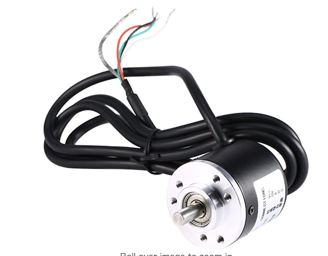
Rotary Encoder in detail is here
- White = A Phase
- Green = B Phase
- Red = Vcc Power+
-
Black = V0
IC : ATtiny3216
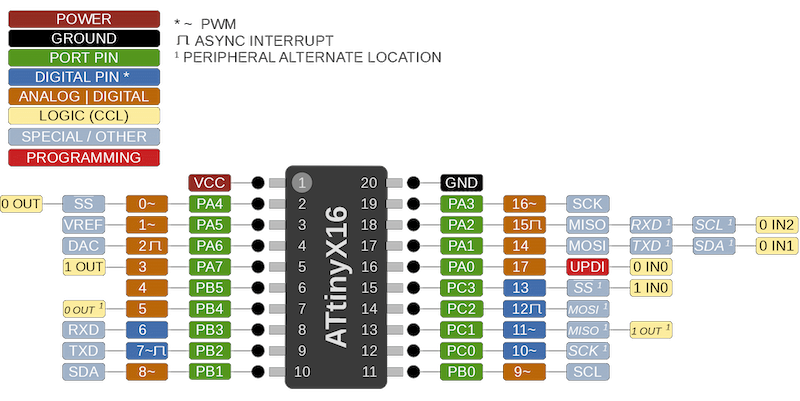
VCC(Red)
1~ = A Phase(White)
0~ = B Phase(Green)
20 = V0(Black)
Process
The process is referenced in this ref
- Design the schematic in Eagle
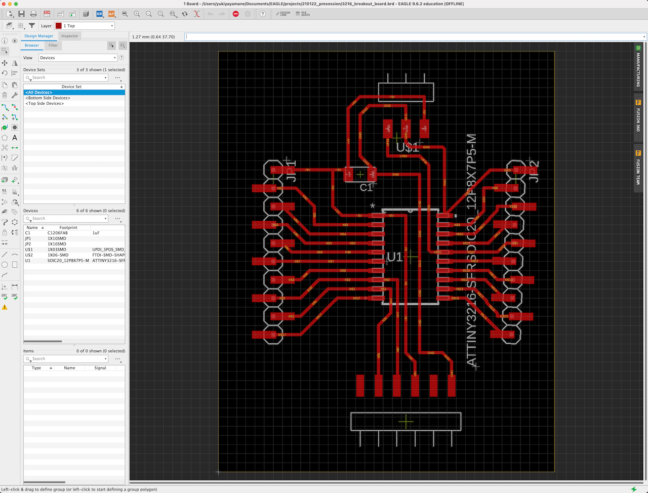
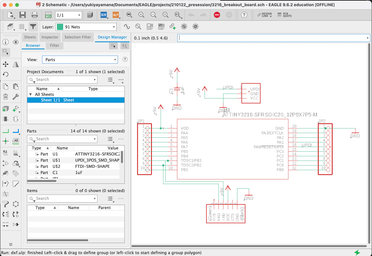
Schematic data is here
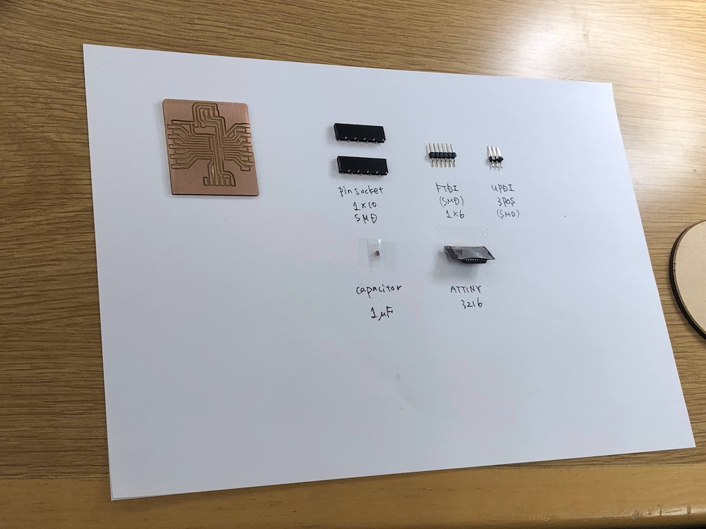
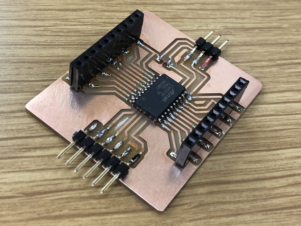
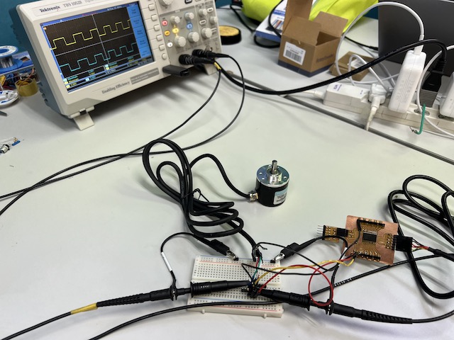
- Soldering parts of breakout board
-
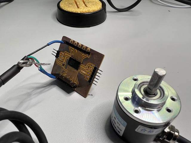
Connect the rotary encoder
-
Edit code in Arduino
/*     Arduino Rotary Encoder Tutorial
 *
 *  by Dejan Nedelkovski, www.HowToMechatronics.com
 *
 */

 #define outputA 1
 #define outputB 0

 int counter = 0;
 int aState;
 int aLastState;

 void setup() {
   pinMode (outputA,INPUT_PULLUP);
   pinMode (outputB,INPUT_PULLUP);

   Serial.begin (9600);
   // Reads the initial state of the outputA
   aLastState = digitalRead(outputA);
 }

 void loop() {
   aState = digitalRead(outputA); // Reads the "current" state of the outputA
   // If the previous and the current state of the outputA are different, that means a Pulse has occured
   if (aState != aLastState){
     // If the outputB state is different to the outputA state, that means the encoder is rotating clockwise
     if (digitalRead(outputB) != aState) {
       counter ++;
     } else {
       counter --;
     }
     Serial.print("Position: ");
     Serial.println(counter);
   }
   aLastState = aState; // Updates the previous state of the outputA with the current state
 }
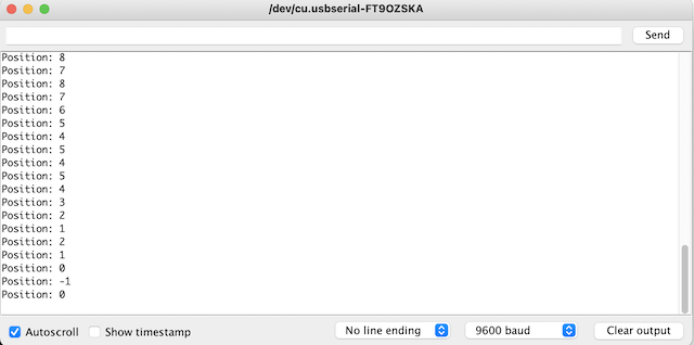
Experiment 1 / Digital Signals
Read Digital Signal of the rotery encoder
- monitor the digital signals through serial monitor
turn clockwise →plus
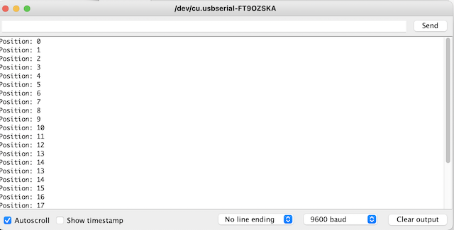
turn anti-clockwise → minus
-
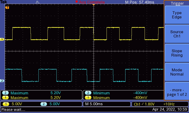
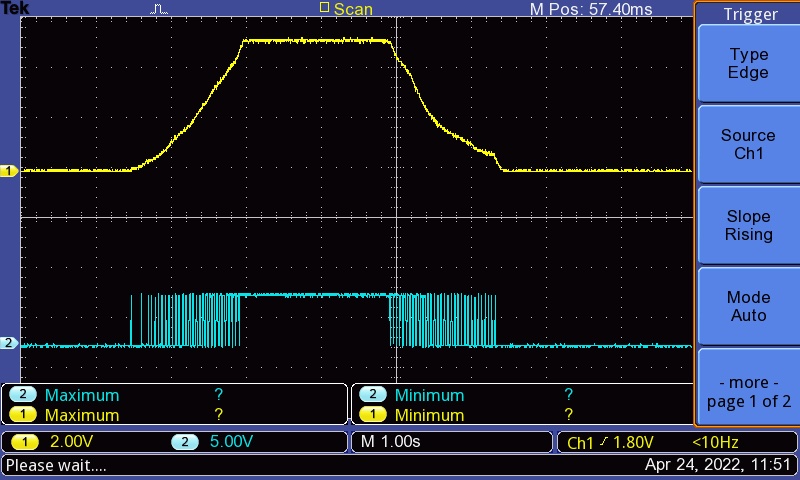
Check the oscilloscope
yellow =A phase
blue =B phase
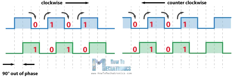
When turning the rotery encoder clockwise
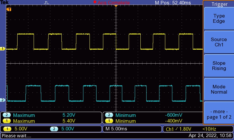
→A phase(yellow) is half a cycle off from B phase(blue).
When A become 0, B phase is at 1. When A become 1, B is at 0.
When turning the rotery encoder counter-clockwise
→A phase(yellow) is half a cycle off from B phase(blue).
When A become 0, B phase is at 0. When A become 1, B is at 1.
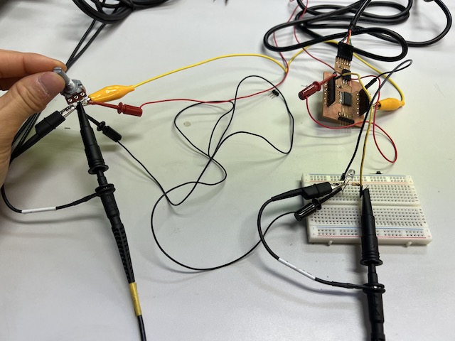
probe an input device’s analog levels by using Variable resisto
Experiment 2 / Analog levels
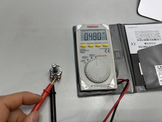
When turned to the left most, 0Ω
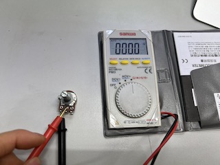
When turned to the right most, 480kΩ
-
Set input to variable resistor ,and output to LED
-
write the code in arduino
int p1 = 0;

void setup() {
  Serial.begin(115200);
  pinMode(9, INPUT);

  pinMode(0, OUTPUT);
}

void loop()
{ p1 = analogRead(9);
//  Serial.println(“p1: 9: “);
  Serial.println(p1);

  int intensity = map(p1, 0, 1024, 0, 255);

  analogWrite(0, intensity);
  delay(10);
}
Turning the resistor to the right to make it larger makes the LED brighter.
The potential difference also increases. The converse is also true
movie