13. Input devices
Insturuction
Individual assignment:
- measure something: add a sensor to a microcontroller board that you have designed and read it →in this page
group assignment:
- probe an input device’s analog levels and digital signals →Here
What I did in this week
- probe an input device’s digital signals by using rotery encoder → Group Assignment
- probe an input device’s analog levels by using Variable resistor → Group Assignment
- add a limited switch to a microcontroller board that you have designed → in this page
- add a phototransistor to a microcontroller board that you have designed → in this page
Add a sensor to a microcontroller board
Plan
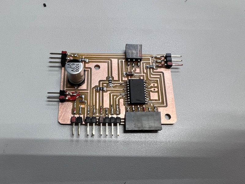
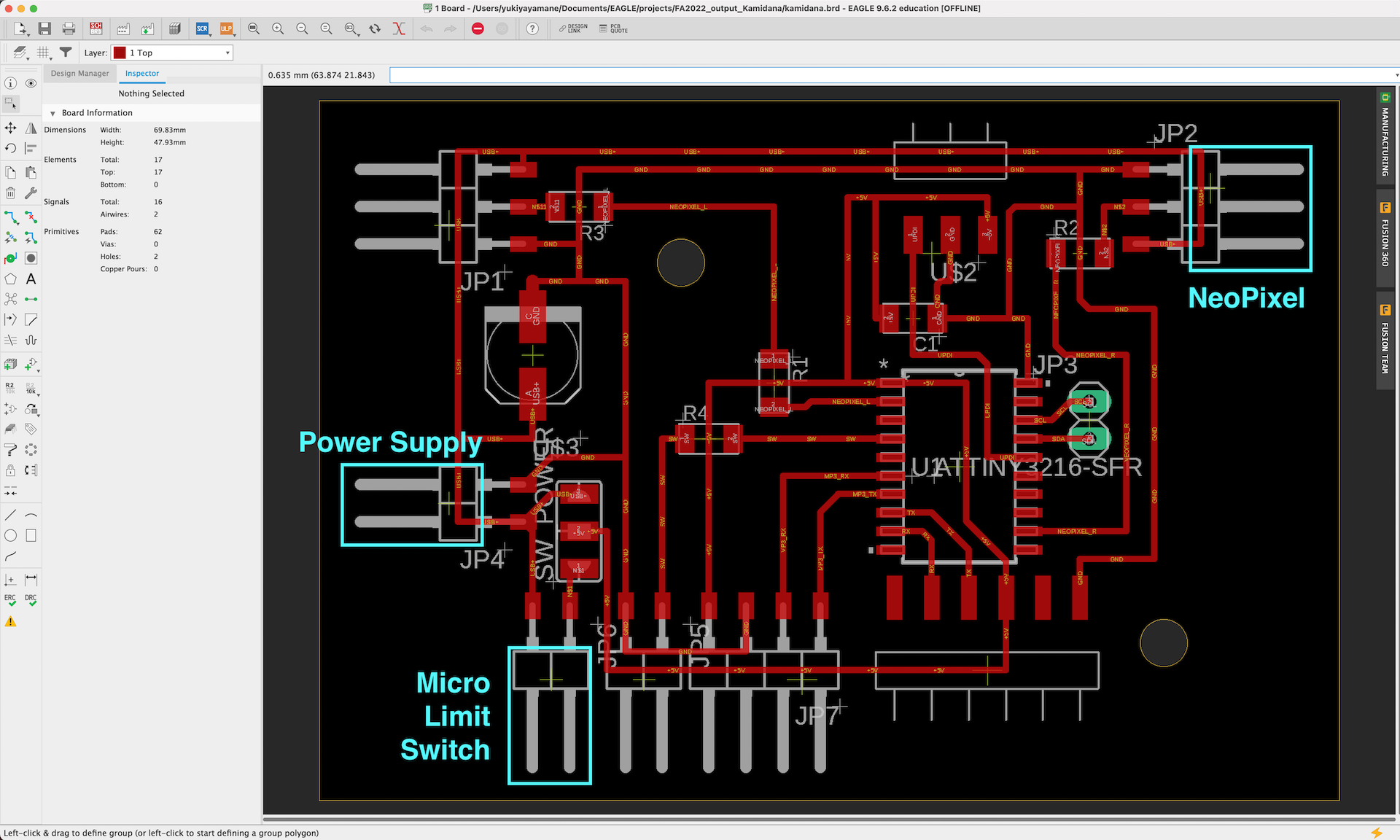
I decided to make the final project parts. The circuit board made in Week 11 was adopted.
Input Devices I will connect to the board
- micro limit switch
- Phototransistor
Process - 1. micro limit switch
-
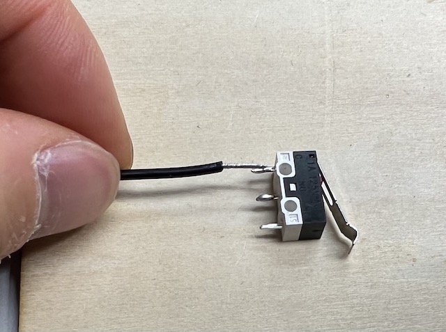
Attach the cable to the micro limit switch by soldering
-
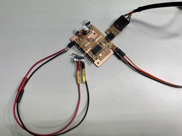
and connect it to the breakout board made by week 11
-
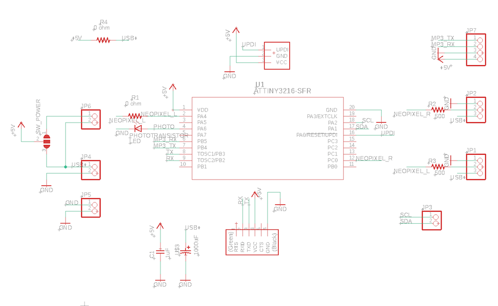
how to connect and use pins
- VCC = ATTiny3216 pin no.1
- Micro Limit Switch = ATTiny3216 pin no.1 (Only when switch is on, the circuit is closed)
- NeoPixel = ATTiny3216 pin no.15
-
Test → Fail
Neopixel lights up when switched on through the power supply. → success
However, the light remains on even when you remove your hand from the switch
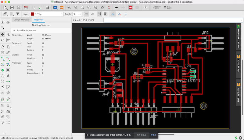
→ The circuit design had resulted in a structure that energizes the Neo Pixel regardless of whether it is switched on or off. Improve the circuit to control the energizing of the two neo pixels with a switch by inserting a 0Ω resistor.
-
Redesign by inserting a 0-ohm resistor.
-
After soldering, connect it to the power supply and turn on the switch.
-
→ success
I was able to make a circuit where the NeoPixel only turns on while the switch is pressed.
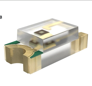
Process - 2. Phototransistor
-
-
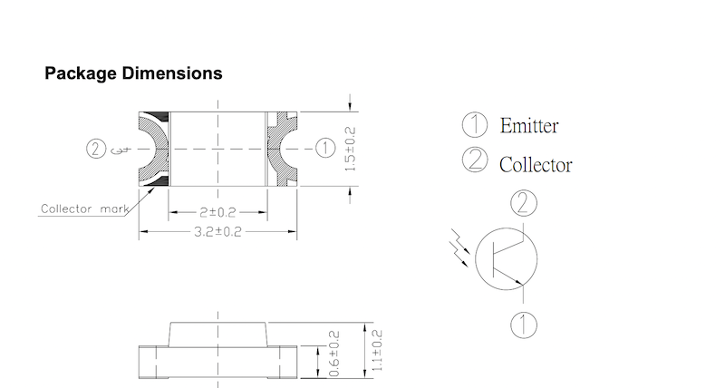
Replace 0Ω. Since there is a peel, insert it carefully in the direction according to data sheet
(Note that the side with the green mark is the pin side and the side without the green mark is the ground side.)
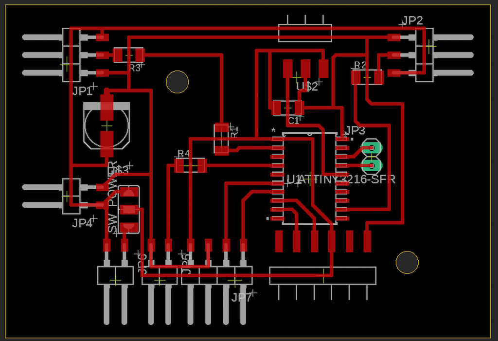
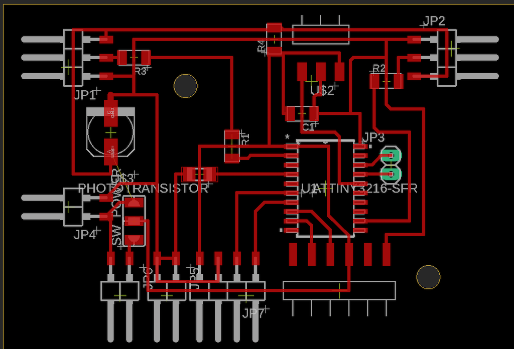
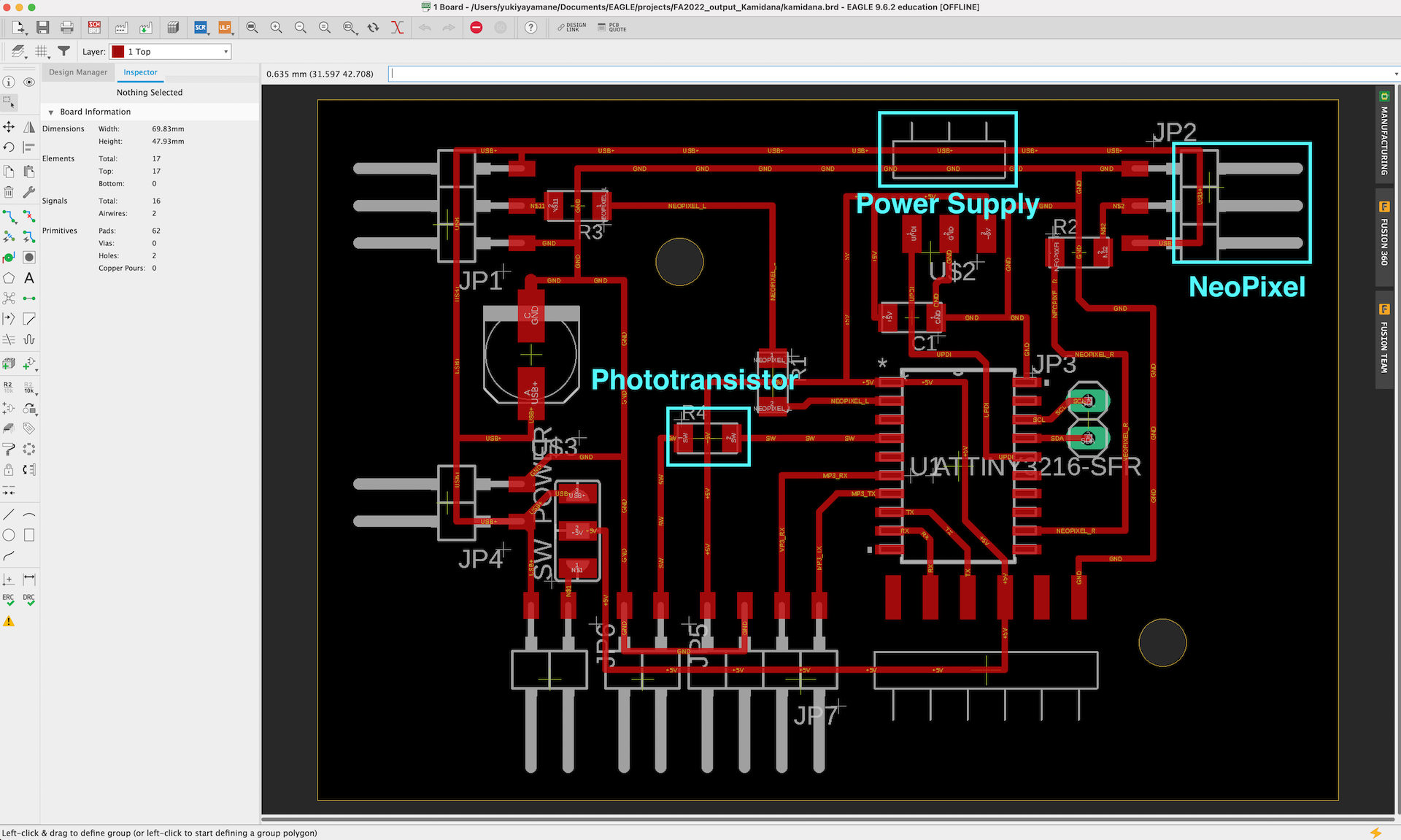
On this board, replace the 0Ω resistor of R4 with a Photo Transistor.
Remove the pins of JP7, and replace them to Ground.
Before
After
-
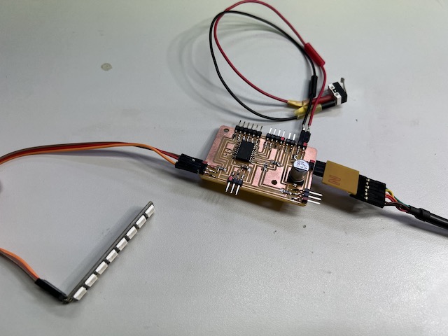
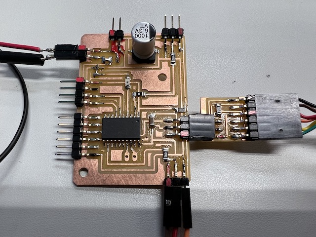
complete the board by inserting photo transistor.
-
how to connect and use pins
- VCC = ATTiny3216 pin no.1
- Micro Limit Switch = ATTiny3216 pin no.1 (Only when switch is on, the circuit is closed)
- Photo Transistor = ATTiny3216 pin no.4
- NeoPixel = ATTiny3216 pin no.15
-
Result
Embeded the program and test Photo transistor
- Write the code of running the phototransistor
#define pinA 2

void setup() {
  pinMode(pinA,INPUT_PULLUP);
  Serial.begin(115200);
  delay(1000);

}

double analogValue;
void loop() {
    analogValue = analogRead(pinA);
    Serial.println(analogValue);
    delay(200);
}
- done
check serial monitor with Indoor light
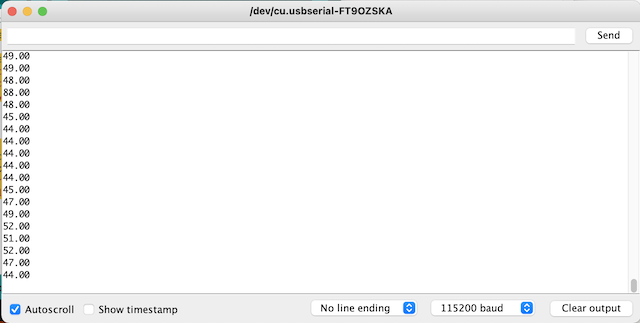
in dark room → Scores get bigger.
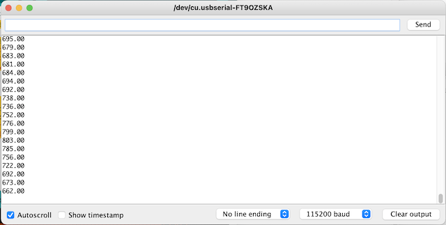
- success!
movie
- Attach the power supply via micro USB. Make sure not to mistake red (VCC) and black (GND).
Programming
- Write the code
When the switch is pressed, the LED lights up. When the surrounding environment becomes dark, the LED dims.
/*

  NeoPixel LEDs

  modified on 7 May 2019
  by Saeed Hosseini @ Electropeak
  https://electropeak.com/learn/

*/

#include <tinyNeoPixel.h>

#define NEOPIXEL_RIGHT  10
#define NUMPIXELS 8
#define PHOTO 2

tinyNeoPixel pixels = tinyNeoPixel(NUMPIXELS, NEOPIXEL_RIGHT, NEO_GRB + NEO_KHZ800);

// int delayval = 500; // delay for half a second
// #define DELAYVAL 500 // Time (in milliseconds) to pause between pixels

void NeoFade(int FadeSpeed)
{
  int fspeed;
  for (int i = 0; i < NUMPIXELS; i++) {
    pixels.setPixelColor(i, 165, 242, 243);
    pixels.show();
  }
  //for (int j = 1; j < 255; j = j + 2)
  //  {
  //    pixels.setBrightness(j);
  //    pixels.show();
  //    delay(FadeSpeed);
  // }
}

void setup() {
  delay(500);
  pixels.begin();
  pixels.clear(); // Set all pixel colors to 'off';

  pinMode(PHOTO, INPUT_PULLUP);

}

double analogValue;
void loop() {

  analogValue = analogRead(PHOTO);
  if (analogValue > 500 ) { //turn dark
    pixels.setBrightness(50); // all pixel colors to 'dark';
    pixels.show();
  } else {
    NeoFade(50); //turn pixel
  }

  delay(200);

}
- Fail:
When the surroundings darken, the pixel also darkens, but
However, when the surroundings are brightened, the pixel does not brighten back up.
- The code was rewritten.
/*

  NeoPixel LEDs

  modified on 7 May 2019
  by Saeed Hosseini @ Electropeak
  https://electropeak.com/learn/

*/

#include <tinyNeoPixel.h>

#define NEOPIXEL_RIGHT  10
#define NUMPIXELS 8
#define PHOTO 2

tinyNeoPixel pixels = tinyNeoPixel(NUMPIXELS, NEOPIXEL_RIGHT, NEO_GRB + NEO_KHZ800);

// int delayval = 500; // delay for half a second
// #define DELAYVAL 500 // Time (in milliseconds) to pause between pixels

void NeoFade(int FadeSpeed)
{
  int fspeed;
  for (int i = 0; i < NUMPIXELS; i++) {
    pixels.setPixelColor(i, 165, 242, 243);
    pixels.show();
  }
  for (int j = 1; j < 255; j = j + 2)
  {
    pixels.setBrightness(j);
    pixels.show();
    delay(FadeSpeed);
  }
}

void NeoON()
{
  //  int fspeed;
  for (int i = 0; i < NUMPIXELS; i++) {
    pixels.setPixelColor(i, 165, 242, 243);
  }
  pixels.setBrightness(255);
  pixels.show();

  //  for (int j = 1; j < 255; j = j + 2)
  //    {
  //      pixels.setBrightness(j);
  //      pixels.show();
  //      delay(FadeSpeed);
  //   }
}

void setup() {
  delay(500);
  pixels.begin();
  pixels.clear(); // Set all pixel colors to 'off';

  pinMode(PHOTO, INPUT_PULLUP);
  NeoFade(50); //turn pixel

}

double analogValue;
void loop() {

  analogValue = analogRead(PHOTO);
  if (analogValue > 500 ) { // when turn dark
    pixels.setBrightness(50); // all pixel colors to 'dark';
    pixels.show();
  } else { // when it is blight
    //    pixels.setBrightness(255);
    NeoON();
    //    NeoFade(50); //turn pixel
  }

  delay(200);

}
→success
What I learned in this week
-
Input devices were connected by using the skills of electric production and embedded programming learned so far.
-
Learned how to define the use of inputs in arduino code and connect them to outputs.
File
phototransistor_serial_test.ino
fading and phototransistor.ino