11. Output devices
Instruction
- individual assignment: add an output device to a microcontroller board you’ve designed, and program it to do something
- group assignment: measure the power consumption of an output device
What I did in this week
- practice to set up the output device by using arduino →Group Page
- try to set it up by using my own breakout board →Group Page
- measure the powerconsumption of an output device →Group Page
- add an output device to a microcontroller board you’ve designed →in this page
- program it to flash LED →in this page
add an output device to a microcontroller board you’ve designed
What I want to make
in order to go ahead with my final project, I need the board to
- control 2 LEDs as output device
- control sounds as output device -> sound will be developed until the final project (not in this week)
- 1 sensor as input device
- UPDI
- Serial communication
- AC
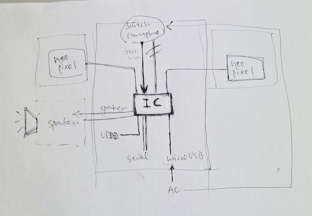
So I choose ATtiny3216 as the micro computer.
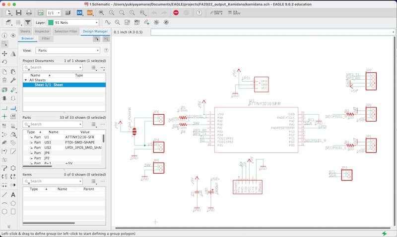
Design the breakout board by Eagle
-
create schematic
-
I designed the board in accordance with the schematic
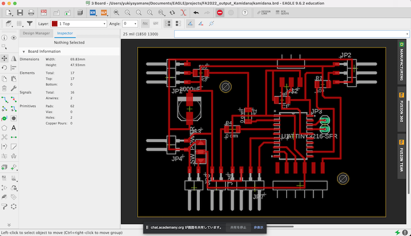
-
drc and finish to design the board
- export png each by selecting the layer 1 top and document
-
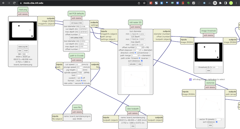
calcurate the milling setting by mods to save as .nc file.
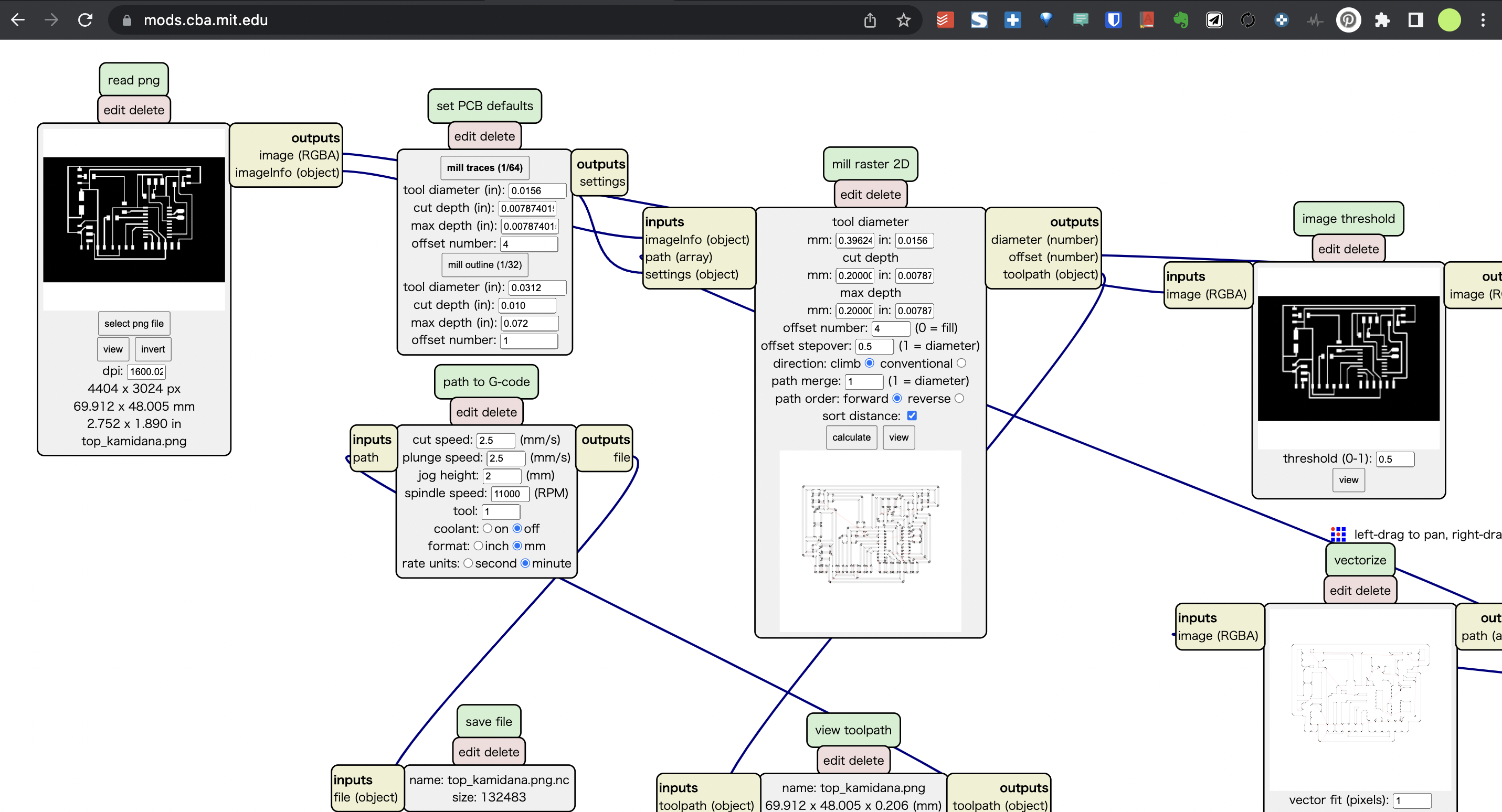
- load to gsender
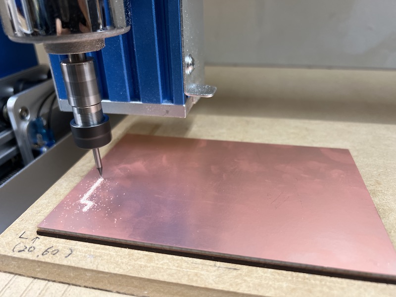
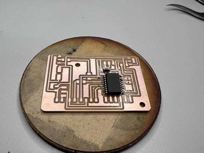
Milling time!
- millng “top” by 1/64 inch endmil
-
millng “board” by 1/32 inch endmil
Soldering
-
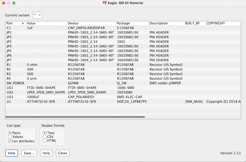
schematic > BOM
-
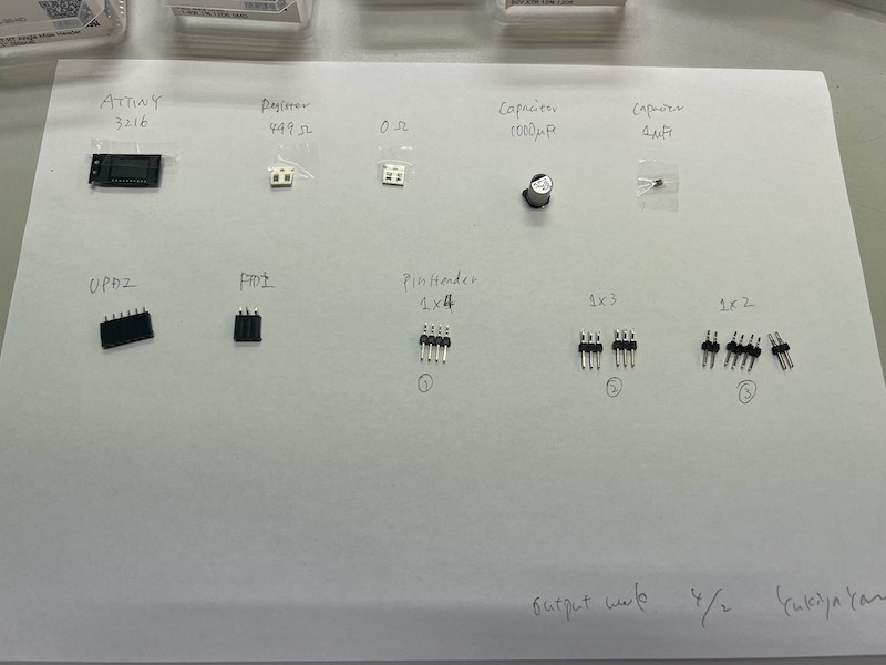
collect the parts I will use
-
Soldering
-
finish to soldering
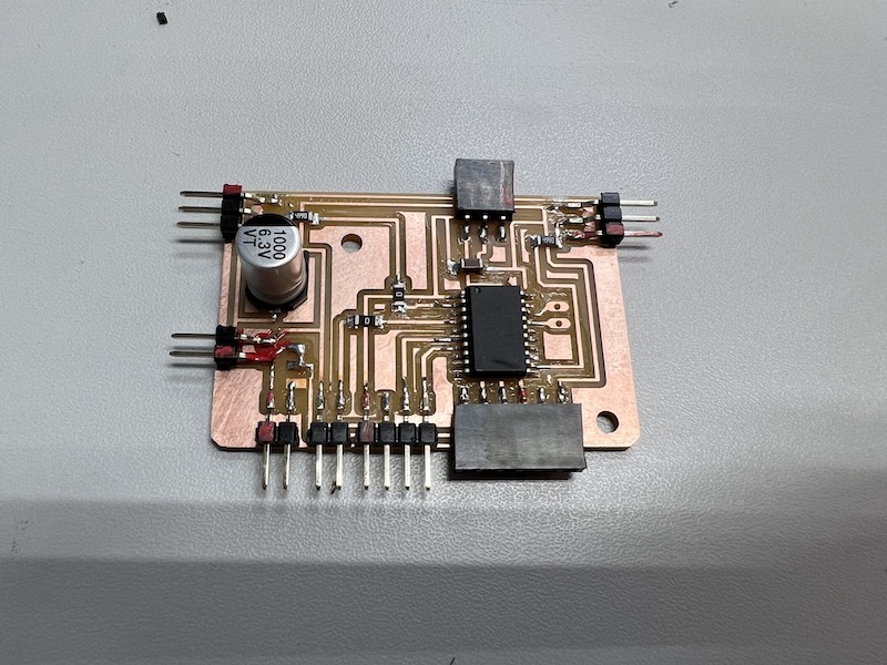
-
embed the code which I write in group assignment to the board
/*

NeoPixel LEDs

modified on 7 May 2019
by Saeed Hosseini @ Electropeak
https://electropeak.com/learn/

*/

#include <tinyNeoPixel.h>

#define PIN       10
#define NUMPIXELS 8

tinyNeoPixel pixels = tinyNeoPixel(NUMPIXELS, PIN, NEO_GRB + NEO_KHZ800);

// int delayval = 500; // delay for half a second
// #define DELAYVAL 500 // Time (in milliseconds) to pause between pixels

void NeoFade(int FadeSpeed)
{
int fspeed;
for (int i = 0; i < NUMPIXELS; i++) { pixels.setPixelColor(i, 165, 242, 243); } for (int j = 1; j < 255; j=j+2)
{
pixels.setBrightness(j);
pixels.show();
delay(FadeSpeed);
}
}

void setup() {
pixels.begin();
pixels.clear(); // Set all pixel colors to 'off'

}

void loop() {
NeoFade(50);
}
-
connect to the NeoPixel LED
What I learned in this week
- Neopixel is so useful because we can control the color and intensity freely
- In milling the board from zero scratch, we have to think about the position of the parts and wiring without interfering each other parts ( sometimes, it is difficult to wire orderly..)
file
Acknowledgement
Mr.Tamiya and Ms.Kamei as supportive instructors in Fablab Kannai
and
and You!
Last update:
July 9, 2022