7. Electronics design
Instruction
Group Assignment
Individual Assignment
- Redraw one of the echo hello-world boards or something equivalent, add (at least) a button and LED (with current-limiting resistor) or equivalent input and output, check the design rules, make it, test it.
- Optionally, simulate its operation.
What I did this week
- Test the operation of a circuit board by multimeter and oscilloscope → Group Assignment
- Design: Redraw the circuit board with botton and LED → in this page
- Check: Design Rule Check and make the circuit board → in this page
- Make: Assemble electronic components to the board→ in this page
- Test: Write programme to the microcomputer on making breakout board→ in this page
2. Design: Redraw and design in Eagle
The board image i will make
- a button
- LED (with current-limiting resistor)
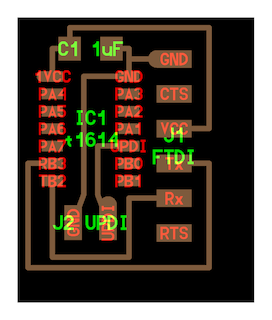
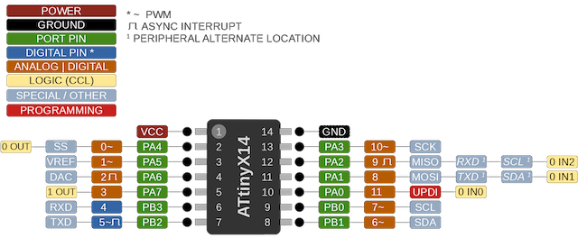
ATTINY 1614
-
add Library
-
eagle/fab.lbr
-
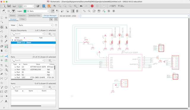
new > schematic
- “add” parts I will use
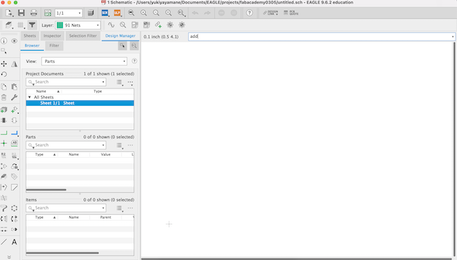
FAB > LEDFAB1216 FAB > R > R1206FAB(Register) FAB > SW_SWITCH_TACTILE_6MM FTDI-SMD-SHAPE UPDI_3POS_SMD_SHAPE PINHD-1X02 CAP_UNPOLARIZEDFAB 5V GND (Version 1)
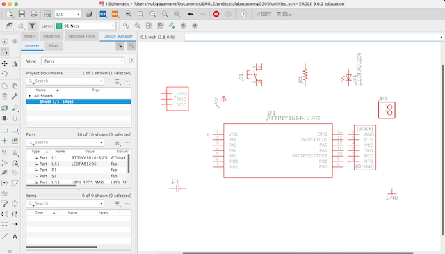
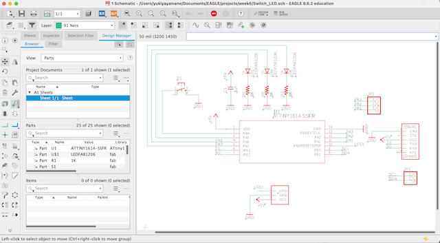
- net and move components in order
- set input “Value”
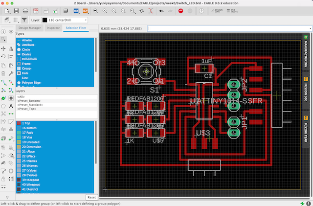
- switch to board mode and put these parts in order
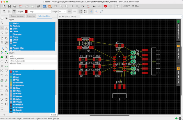
- drawing by “Route Airwire”
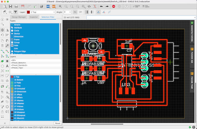
- draw the layout by “POLYGON”
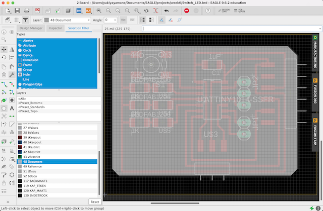
- Assign Shortcut of making hole to F12 in accordance with this instruction
option > assign > new
SET COLOR_LAYER 116 0;SET FILL_LAYER 116 1;run drill-aid 0
- making holes by press “F12”
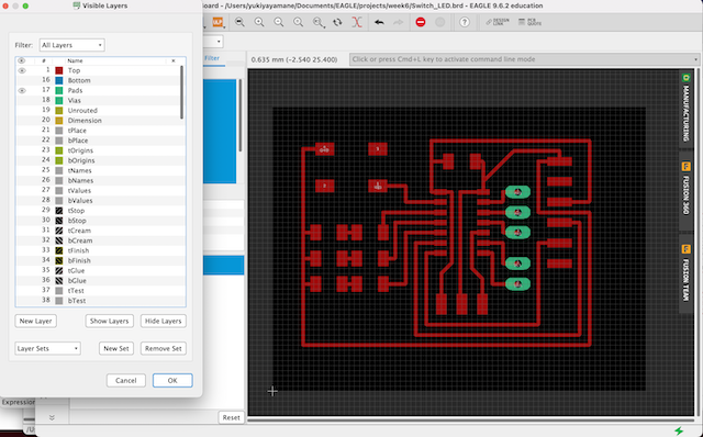
- hide layers and display only top and pats
3. Check: DRC (Design Rule Check)
Validating your work through the use of a Design Rule Check (DRC).
- press drc and set clearance parameters “16mil”
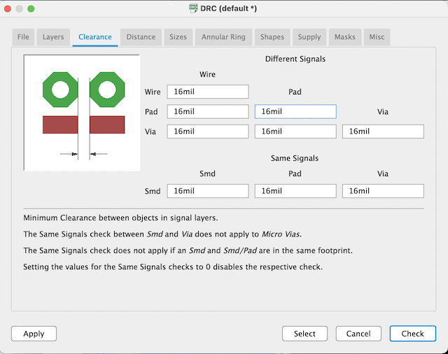
- press command : drc
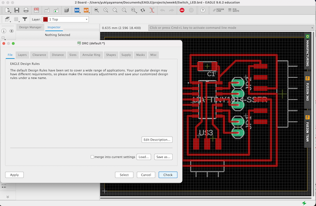
After that, nothing is displayed. Turns out there was no problem.
Draw pathroute by mods in accordance with exported the design data
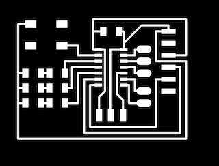
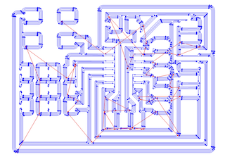
- select top and pad → export as filename “top”
file > export > image
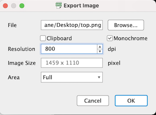
- Export “top.png”image
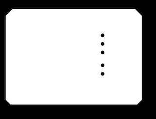
- display only document and centerdrill
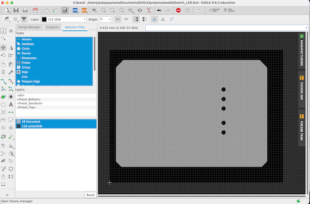
- export image as filename “holes_outline.png” in the same setting
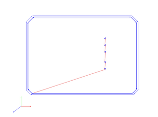
- import the image to mods and calculate pathroute by mods
Size: 46.3 x 35.2 mm
- launch the image in gSender and connect PC to CNC machine
CNC machine I used : Genmitsu PROVerXL 4030
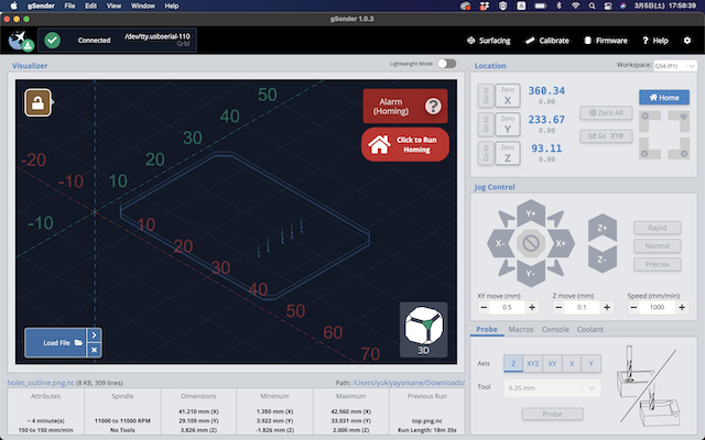
- press homing
- install endmill (1/64) and set its position
- load file .nc and start job
- image of milling by 1/64
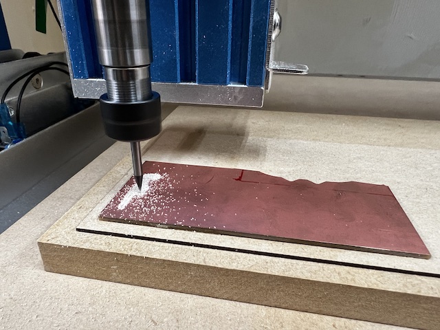
- after detaching endmill (1/64), install endmill (1/32) and set its position
- video of milling by 1/32
- done
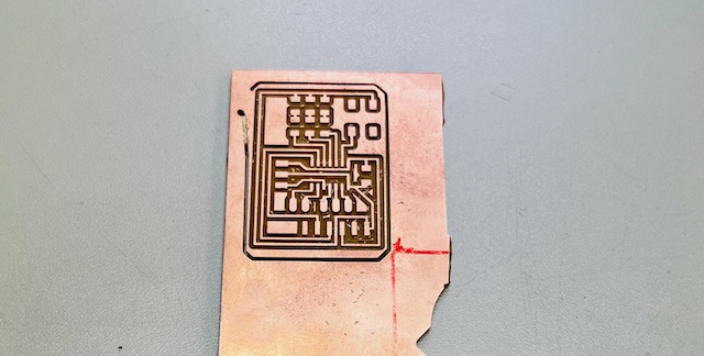
At the end of milling, unfortunately the circuit board came un stick because the board wasn’t fixed enough by glue. So I couldn’t cut the board completely. As the cutting process was almost finished, I decided to cut the remaining by pliers.
4. Make: Assemble electronic components to the circuit board
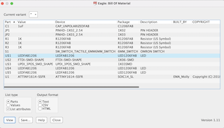
- export to “bom” from brd and display parts list
- collect components
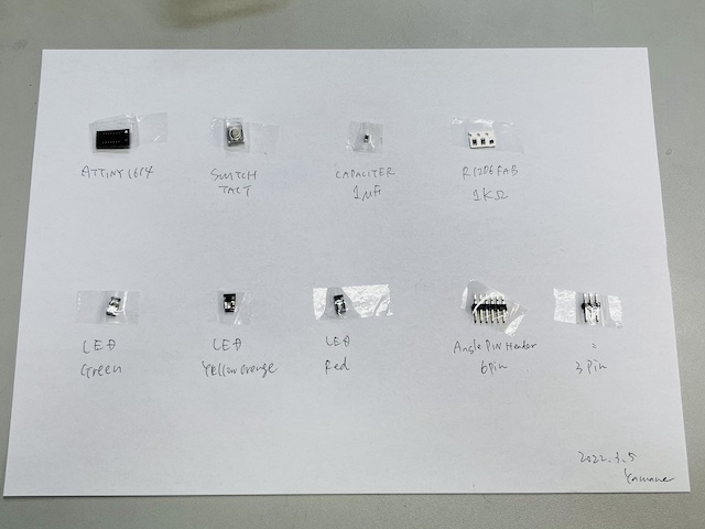
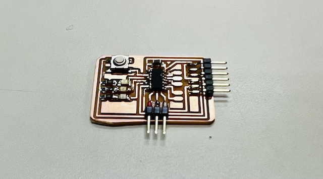
- Soldering
5. Test: Write programme to the microcomputer on making breakout board
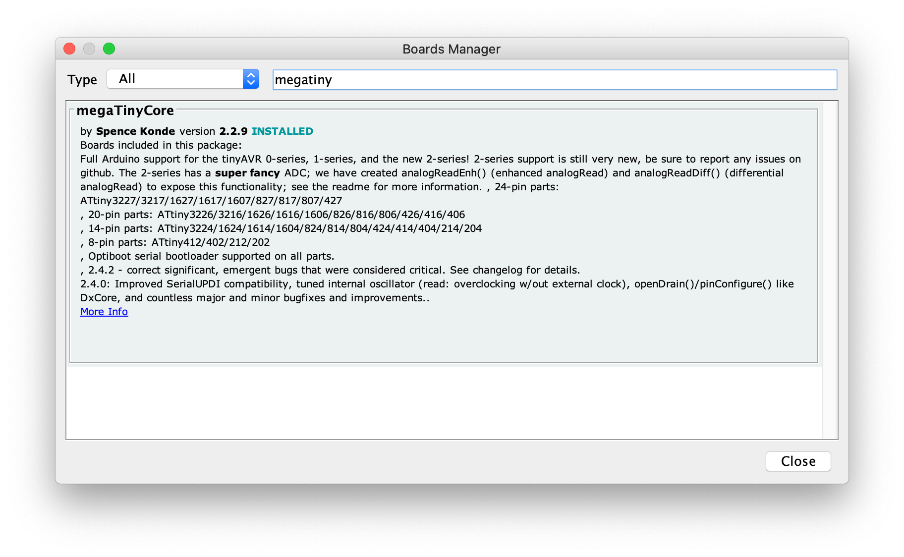
- setup ATtiny1614
File -> PreferencesAdditional Board Manager URLs:
http://drazzy.com/package_drazzy.com_index.json
Boards Manager
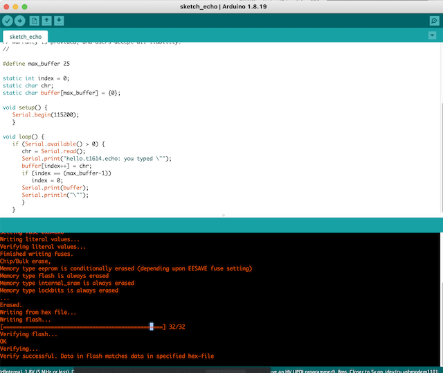
- write echo program to the breakout board
//
// hello.t1614.echo.ino
//
// tiny1614 echo hello-world
//    115200 baud
//
// Neil Gershenfeld 12/22/19
//
// This work may be reproduced, modified, distributed,
// performed, and displayed for any purpose, but must
// acknowledge this project. Copyright is retained and
// must be preserved. The work is provided as is; no
// warranty is provided, and users accept all liability.
//

#define max_buffer 25

static int index = 0;
static char chr;
static char buffer[max_buffer] = {0};

void setup() {
   Serial.begin(115200);
   }

void loop() {
   if (Serial.available() > 0) {
      chr = Serial.read();
      Serial.print("hello.t1614.echo: you typed \"");
      buffer[index++] = chr;
      if (index == (max_buffer-1))
         index = 0;
      Serial.print(buffer);
      Serial.println("\"");
      }
   }
- setting in arduino
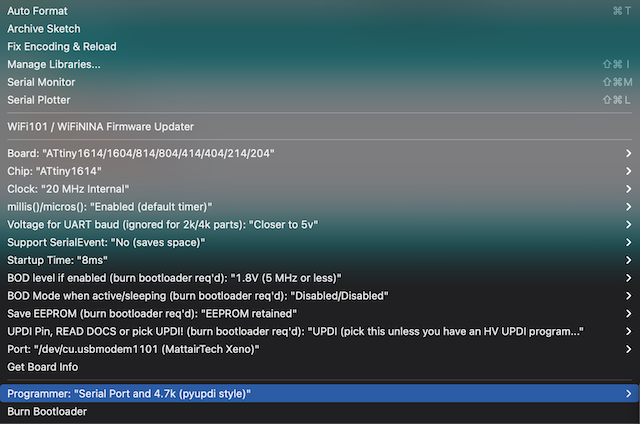
- complete writing
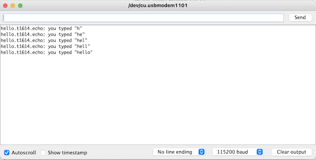
- Check with serial monitor by connecting to serial
- Confirmation that echo is returned without any problem.
- write the programme of Blink of Red/Yellow/Blue LED in turn
// the setup function runs once when you press reset or power the board
void setup() {
// initialize digital pin LED_BUILTIN as an output.
pinMode(1, OUTPUT);
pinMode(2, OUTPUT);
pinMode(3, OUTPUT);

}

// the loop function runs over and over again forever
void loop() {
digitalWrite(1, HIGH);   // turn the LED on (HIGH is the voltage level)
delay(1000);                       // wait for a second
digitalWrite(1, LOW);    // turn the LED off by making the voltage LOW
delay(1000);                       // wait for a second

digitalWrite(2, HIGH);   // turn the LED on (HIGH is the voltage level)
delay(1000);                       // wait for a second
digitalWrite(2, LOW);    // turn the LED off by making the voltage LOW
delay(1000);                       // wait for a second

digitalWrite(3, HIGH);   // turn the LED on (HIGH is the voltage level)
delay(1000);                       // wait for a second
digitalWrite(3, LOW);    // turn the LED off by making the voltage LOW
delay(1000);                       // wait for a second

}
done!
What I learned this week
Individual and Group Assignment
- Understand how information can be sent through an electronic board.
- Using an oscilloscope allows you to feel that the microcontroller is working.
- Combination of only 0 and 1 can be conveyed the imformation to MCU by electrically controlled potential differences.
- The first thing to do after building a foundation is to write echo and blink of LED programme
- Imagined how amazing it is that every electronic device in the world is controlled by a microcomputer.
file
Acknowledgement
Mr.Tamiya and Ms.Kamei as supportive instructors in Fablab Kannai
and You!