9. Embedded programming
Instruction
Group Assignment
Individual Assignment
- read the data sheet for your microcontroller
- use your programmer to program your board to do something
- extra credit: try other programming languages and development environments
What I did this week
- use and compare the performance of microbit, Arduino Pico and Seeeduino Xiao →in this page →Here
- browse the datasheet of ATtiny3216 I used → in this page
- write some programs to control illuminating LEDs by using my programmer→in this page
Use the breakout board I made in week07
Week07 page is here
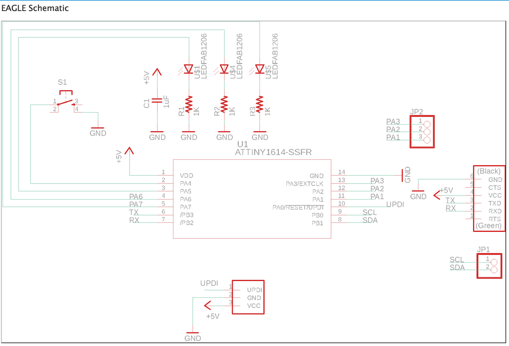
- Schematic is below
Browse the datasheet of ATtiny1614
- access to datasheet
- The ATtiny1614 are members of the tinyAVR® 1-series of microcontrollers,
- using the AVR® processor with hardware multiplier,
- running at up to 20 MHz,
- with 16 KB Flash,
- 2 KB of SRAM,
- and 256 bytes of EEPROM in a 14-pin package
-
tinyAVR® 1-series Overview
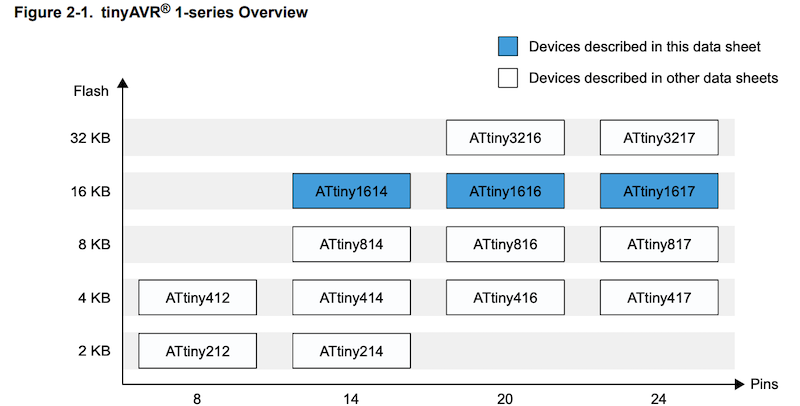
-
Pin out
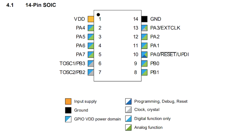
-
cheetsheet which the correspondence shown.is here
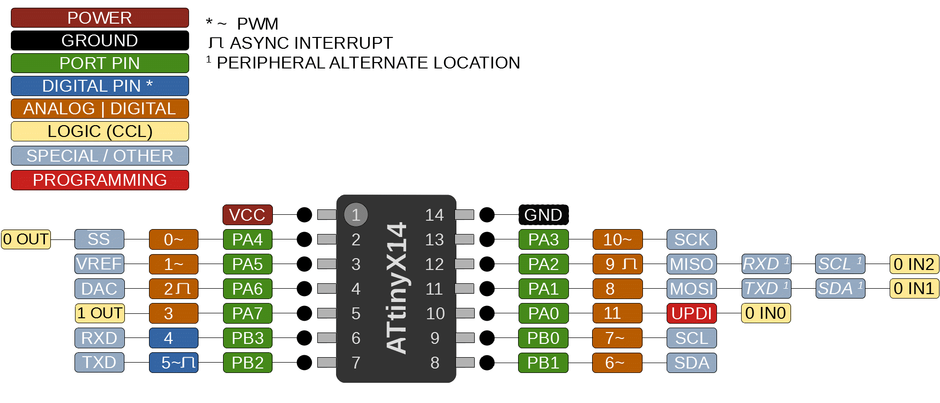
-
Refer to Data Direction and Output Value
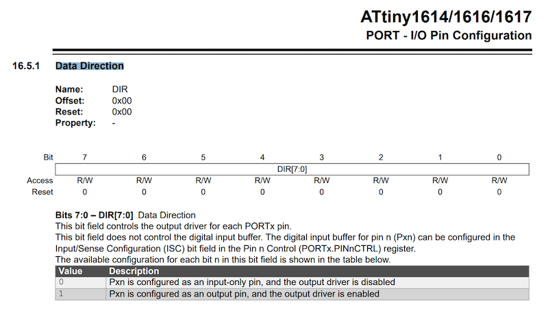
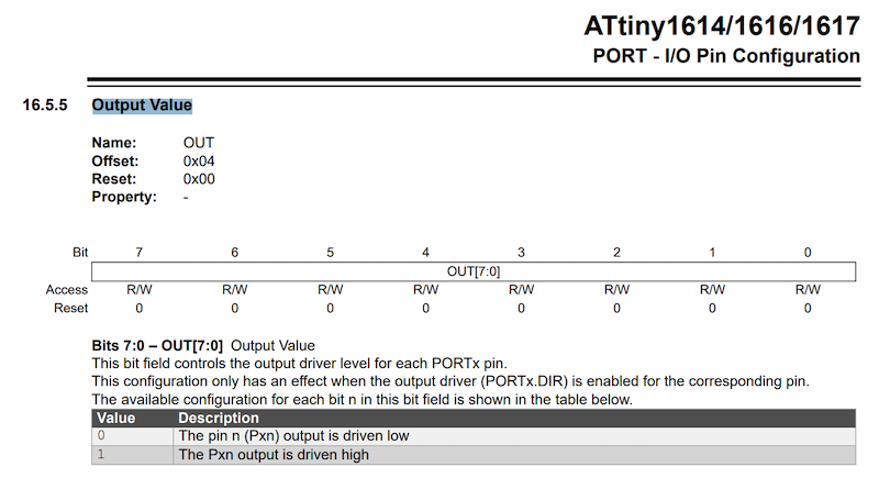
- operating from register bits
// the setup function runs once when you press reset or power the board
void setup() {
  // initialize digital pin LED_BUILTIN as an output.
  PORTA.DIR |= 0b00100000; //Set PortA No.5 Pin(No.1 Pin in Arduino) as OUTPUT
}

// the loop function runs over and over again forever
void loop() {
  PORTA.OUT |= 0b00100000;//ポートAの5番ピン(Arduinoの1番ピン)をHIGH
  delay(500);
  PORTA.OUT &= ~0b00100000;//ポートAの5番ピン(Arduinoの1番ピン)をLOW
  delay(500);
}
- The same program written in Arduino is below
void setup() {
  pinMode(1, OUTPUT);
}
void loop() {
  digitalWrite(1,HIGH);
  delay(500);
  digitalWrite(1,LOW);
  delay(500);
}
Setup ATtiny1614
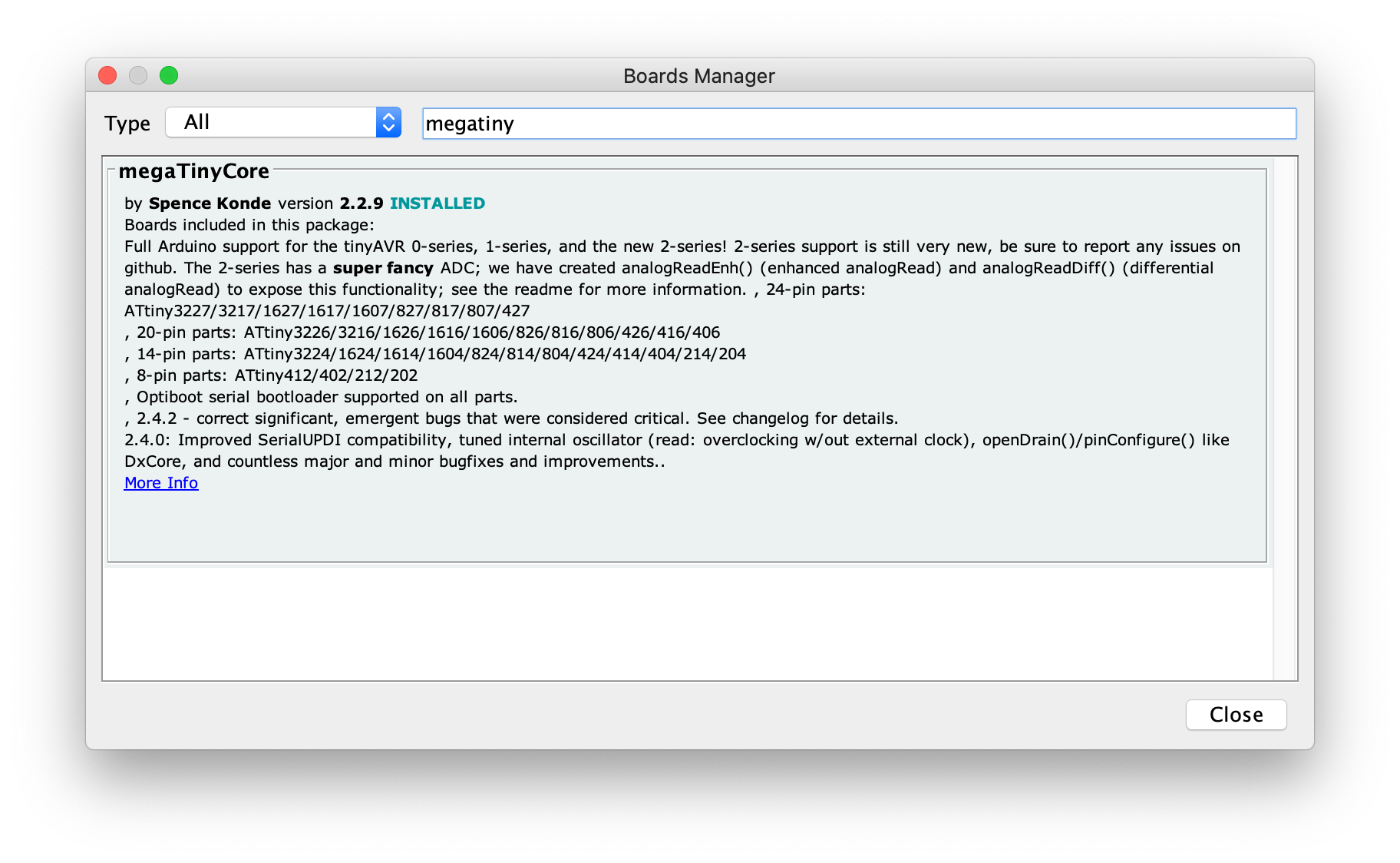
File -> PreferencesAdditional Board Manager URLs:
http://drazzy.com/package_drazzy.com_index.json
Boards Manager
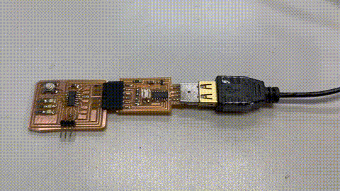
Program 1 :Press button, illuminate 1 LED
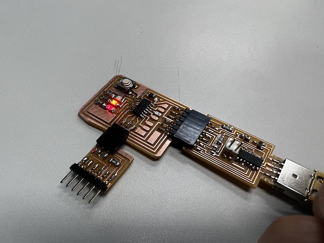
- The breakout board I made in week07 . I have checked to work LED blink
- edit code in arduino
const int BUTTON = 0;
const int LED = 1;
int BUTTONstate = 0;

void setup()
{
  pinMode(BUTTON, INPUT_PULLUP);
  pinMode(LED, OUTPUT);
}

void loop()
{
  BUTTONstate = digitalRead(BUTTON);
  if (BUTTONstate == LOW)
  {
    digitalWrite(LED, HIGH);
  }
  else{
    digitalWrite(LED, LOW);
  }
}
- However. it didnt work the button as nothing operates by pressing the button
Debugging
- Check whether soldering is no problem by using the microscope
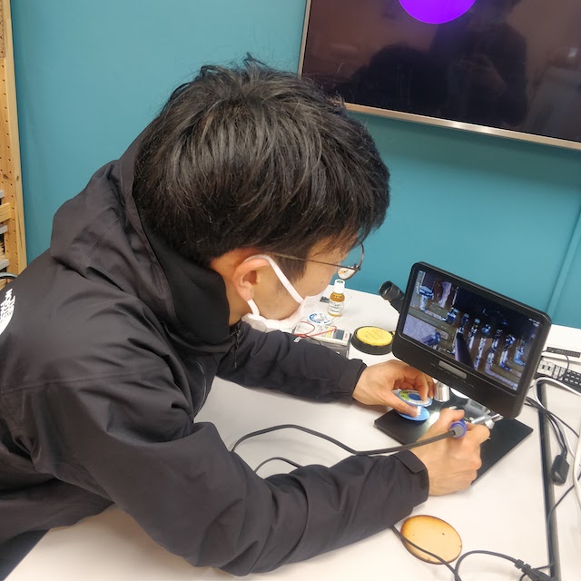
-
There seemed to be a problem with the IC leading to the button part
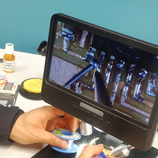
-
so I sucked out the solder once and try to solder again.
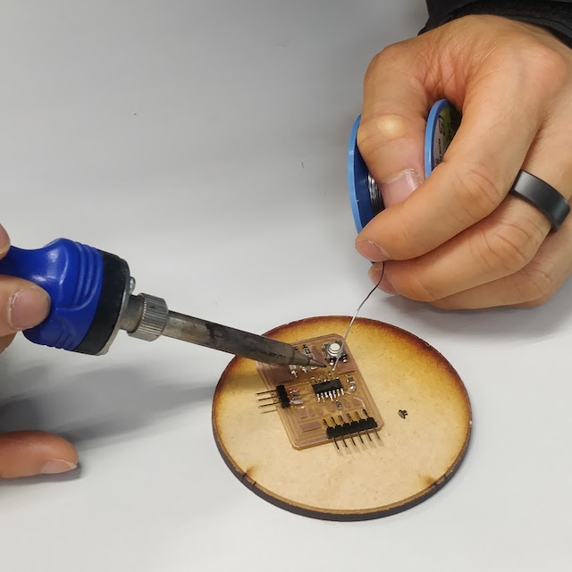
- It can work :)
Program 2 : illuminate 3 LEDs ( refer to the sample code )
- Edit code reffering the code which the student last year has written
- This is the program whichilluminating LEDs change in accordance with pressing the button
const int buttonPin = 0;     // the number of the pushbutton pin
const int ledPin1 =  1;      // the number of the LED pin
const int ledPin2 =  2;      // the number of the LED pin
const int ledPin3 =  3;      // the number of the LED pin

// variables will change:
int buttonState = 0;         // variable for reading the pushbutton status
int buttonCount =  0;

// int delay_interval = 0;

void setup() {
Serial.begin(115200);
// initialize the LED pin as an output:
pinMode(ledPin1, OUTPUT);
// initialize the pushbutton pin as an input:
pinMode(ledPin2, OUTPUT);
// initialize the pushbutton pin as an input:
pinMode(ledPin3, OUTPUT);
// initialize the pushbutton pin as an input:
pinMode(buttonPin, INPUT_PULLUP);
}

void loop() {
// read the state of the pushbutton value:
buttonState = digitalRead(buttonPin);
Serial.print("buttonState: ");
Serial.println(buttonState);
Serial.print("buttonCount: ");
Serial.println(buttonCount);

if (buttonState == LOW) {
  buttonCount+=  1;
  delay(3000);
  if (buttonCount > 3) {
    buttonCount = 0;
  }
}

if (buttonCount == 0) {
  digitalWrite(ledPin1, LOW);
  digitalWrite(ledPin2, LOW);
  digitalWrite(ledPin3, LOW);
} else if (buttonCount == 1) {
  digitalWrite(ledPin1, HIGH);
  delay(100);
  digitalWrite(ledPin1, LOW);
  delay(100);
} else if (buttonCount == 2) {
  digitalWrite(ledPin2, HIGH);
  delay(500);
  digitalWrite(ledPin2, LOW);
  delay(500);
} else if (buttonCount == 3) {
  digitalWrite(ledPin3, HIGH);
}

}
- Upload to the board and do it.
Program 3 : Arrange by my self
- The program which more LEDs illuminates in accordance with pressing the button
const int buttonPin = 0;     // the number of the pushbutton pin
const int ledPin1 =  1;      // the number of the LED pin
const int ledPin2 =  2;      // the number of the LED pin
const int ledPin3 =  3;      // the number of the LED pin

// variables will change:
int buttonState = 0;         // variable for reading the pushbutton status
int buttonCount =  0;

int delay_interval = 0;

void setup() {
Serial.begin(115200);
// initialize the LED pin as an output:
pinMode(ledPin1, OUTPUT);
// initialize the pushbutton pin as an input:
pinMode(ledPin2, OUTPUT);
// initialize the pushbutton pin as an input:
pinMode(ledPin3, OUTPUT);
// initialize the pushbutton pin as an input:
pinMode(buttonPin, INPUT_PULLUP);
}

void loop() {
// read the state of the pushbutton value:
buttonState = digitalRead(buttonPin);
Serial.print("buttonState: ");
Serial.println(buttonState);
Serial.print("buttonCount: ");
Serial.println(buttonCount);

if (buttonState == LOW) {
  buttonCount+=  1;
  delay(3000);
  if (buttonCount > 3) {
    buttonCount = 0;
  }
}

if (buttonCount == 0) {
  digitalWrite(ledPin1, LOW);
  digitalWrite(ledPin2, LOW);
  digitalWrite(ledPin3, LOW);
} else if (buttonCount == 1) {
  digitalWrite(ledPin1, HIGH);
  delay(100);
  digitalWrite(ledPin1, LOW);
  delay(100);
} else if (buttonCount == 2) {
  digitalWrite(ledPin1, HIGH);
  digitalWrite(ledPin2, HIGH);
  delay(200);
  digitalWrite(ledPin1, LOW);
  digitalWrite(ledPin2, LOW);
  delay(200);
} else if (buttonCount == 3) {
  digitalWrite(ledPin1, HIGH);
  digitalWrite(ledPin2, HIGH);
  digitalWrite(ledPin3, HIGH);
  delay(300);
  digitalWrite(ledPin1, LOW);
  digitalWrite(ledPin2, LOW);
  digitalWrite(ledPin3, LOW);
  delay(300);;
}

}
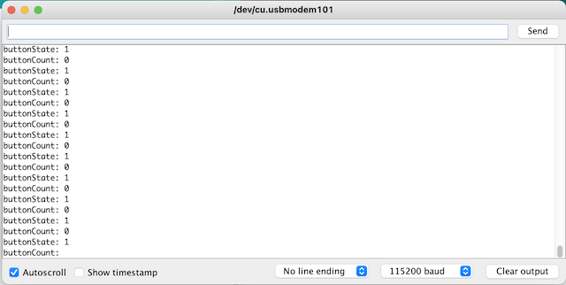
- Upload to the board and do it.
-
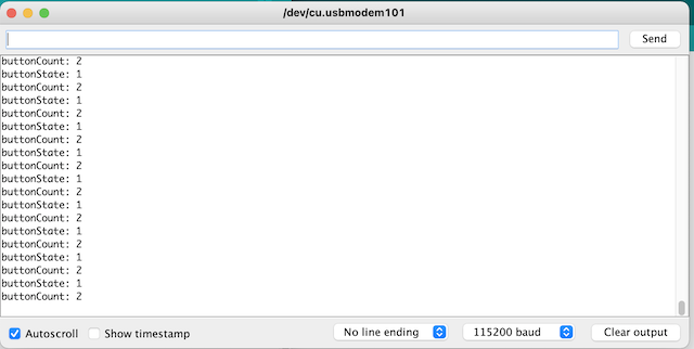
Monitor the signal in serial monitor. Initial state which no bottun press is below.
-
When press button once, it becomes count 1 / state 1
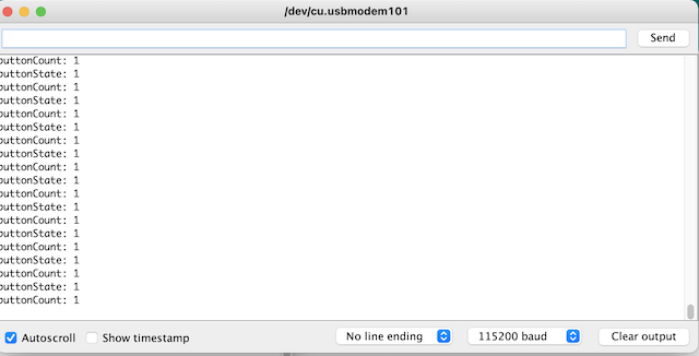
-
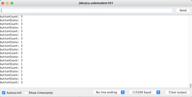
When press button again, it becomes count 2 / state 1
-
When press button again, it becomes count 3 / state 1
Program 4 : Try to control of LEDs by serial monitor in Arduino
- set the number to control the board as follow
- send “1”, turn on the LED of green. “4”, turn off.
- send “2”, turn on the LED of Orange. “5”, turn off.
- send “3”, turn on the LED of Red. “6”, turn off.
- send “9”, turn off the all LEDs.
- edit code
const int buttonPin = 0;     // the number of the pushbutton pin
const int ledPin1 =  1;      // the number of the LED pin
const int ledPin2 =  2;      // the number of the LED pin
const int ledPin3 =  3;      // the number of the LED pin
int incomingByte = 0;

// variables will change:
int buttonState = 0;         // variable for reading the pushbutton status
int buttonCount =  0;

int delay_interval = 0;

void setup() {
  Serial.begin(115200);
  // initialize the LED pin as an output:
  pinMode(ledPin1, OUTPUT);
  // initialize the pushbutton pin as an input:
  pinMode(ledPin2, OUTPUT);
  // initialize the pushbutton pin as an input:
  pinMode(ledPin3, OUTPUT);
  // initialize the pushbutton pin as an input:
  pinMode(buttonPin, INPUT_PULLUP);
}

void loop() {

  // send data only when you receive data:
  if (Serial.available() > 0) {
    // read the incoming byte:
    incomingByte = Serial.read();

    Serial.print("I received: ");
    Serial.println((char)incomingByte, DEC);
  }

  if ( incomingByte == '0') {  //do nothing

  } else if ( incomingByte == '1') {
    digitalWrite(ledPin1, HIGH); // turn on LED1
  } else if (incomingByte == '2') {
    digitalWrite(ledPin2, HIGH);
  } else if (incomingByte == '3') {
    digitalWrite(ledPin3, HIGH);
  } else if ( incomingByte == '4') {
    digitalWrite(ledPin1, LOW);
  } else if (incomingByte == '5') {
    digitalWrite(ledPin2, LOW);
  } else if (incomingByte == '6') {
    digitalWrite(ledPin3, LOW);

  } else if (incomingByte == '9') {
    digitalWrite(ledPin1, LOW);
    digitalWrite(ledPin2, LOW);
    digitalWrite(ledPin3, LOW);
  } else {
  }
}

// say what you got:
// Serial.print("I received: ");
// Serial.println(incomingByte, DEC);
// }
-
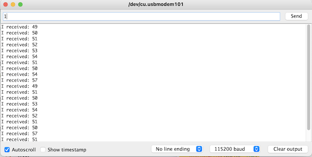
check the serial monitor
-
number is written in ASCII Character Set
- 49(ASCII) = digit 1
- 50(ASCII) = digit 2
- 51(ASCII) = digit 3
- done
What I learned this week
Individual and Group Assignment
- Learned to write programs to a microcomputer through a programmer
- Became able to blink LEDs by pressing button and by controlling serial monitor
- There are many kinds of programming kit and some of them can be controlled only visual programing without any coding.
File
Acknowledgement
Mr.Tamiya and Ms.Kamei as supportive instructors in Fablab Kannai
and You!