12. Mechanical design / Machine design
Instruction
1.1 Mechanical Design (part 1 of 2)
Group assignment: Design a machine that includes mechanism + actuation + automation Build the mechanical parts and operate it manually. Document the group project -> FabLab Armenia Dilijan and Fablab Kannai Group Page
Individual assignment:Document your individual contribution. -> in this page
1.2 Machine Design (part 2 of 2)
Group assignment:Actuate and automate your machine. Document the group project -> FabLab Armenia Dilijan and Fablab Kannai Group Page
Individual assignment:Document your individual contribution. -> in this page
Briefing
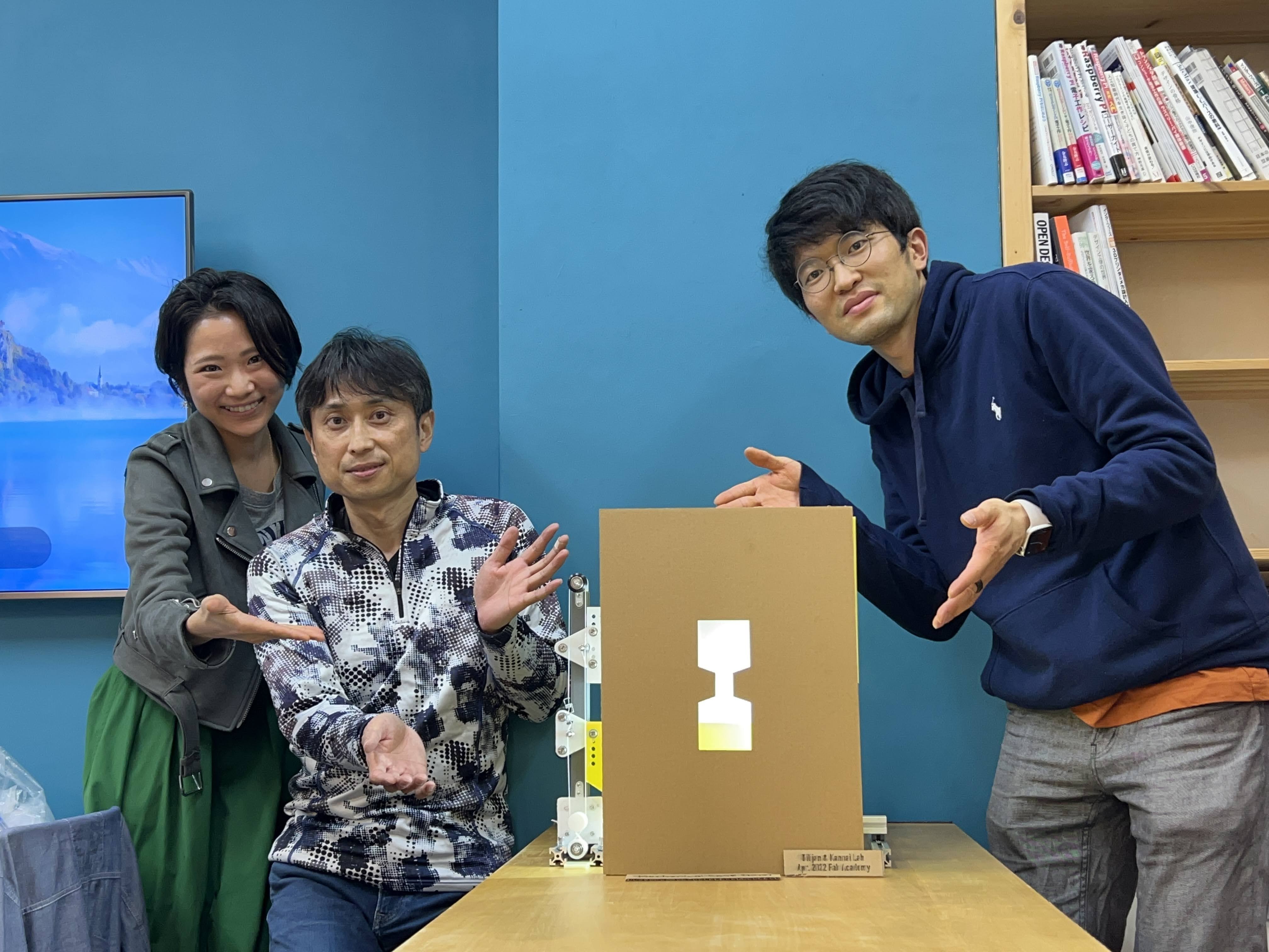
We decided to collaborate with Dilijian, Armenia for this assignment.
First we created a group in Mattermost to keep in touch and to upload different content for us.
We started dividing the time with a schedule, so we would have a tidy process.
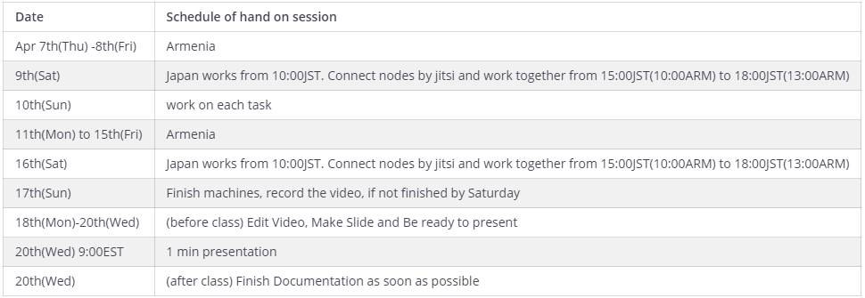
And as well, we had regular meetingsx
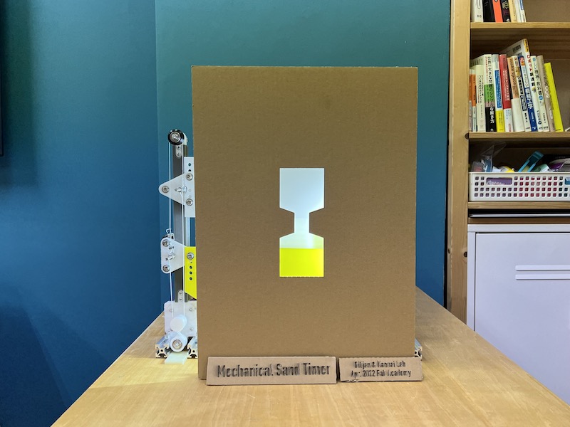
Final Product
Details are written in **Dilijian-Kannai Group Site.**
Design Process
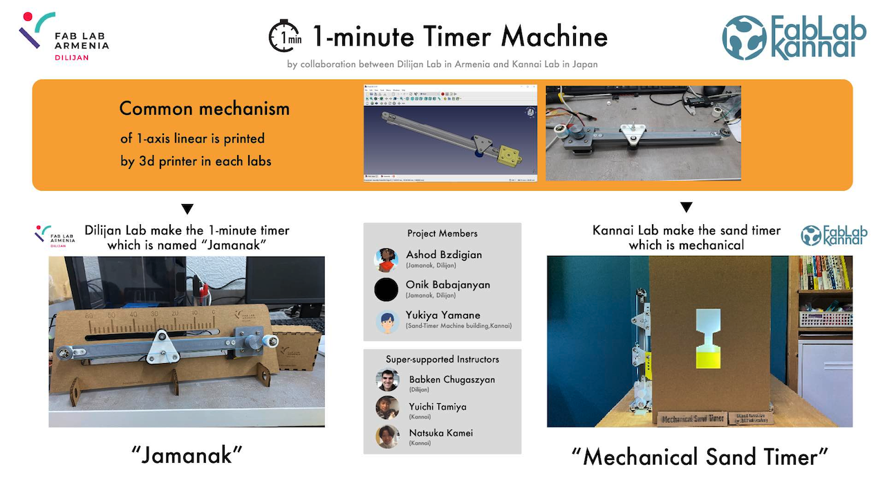
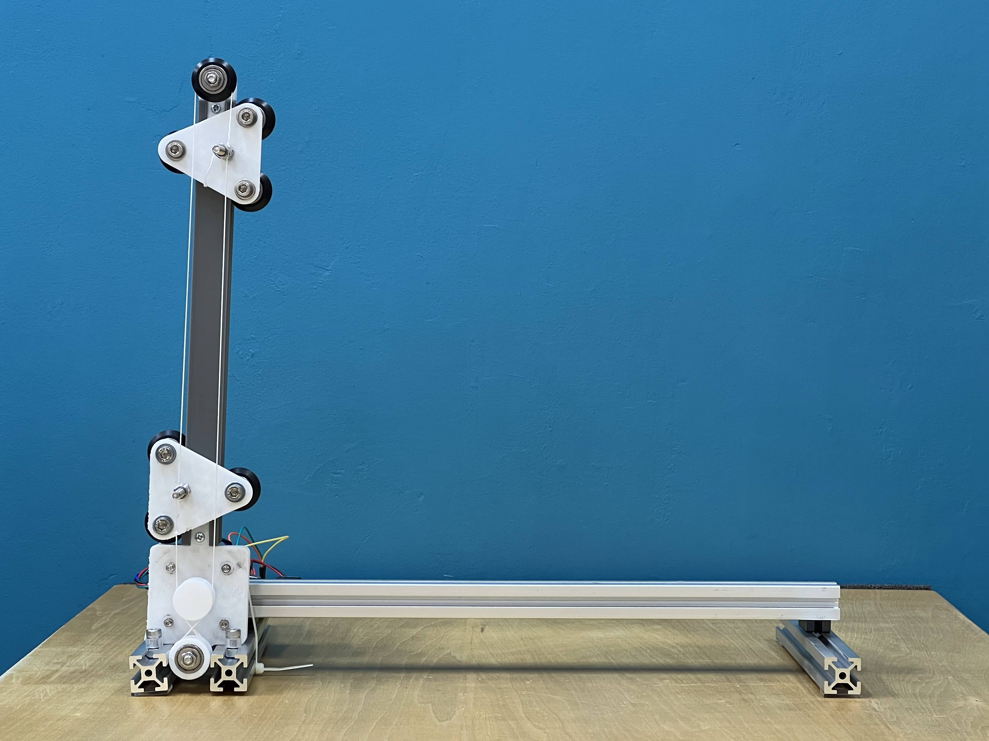
It was decided that the 1 liniar axis moving parts to be output by 3D printing would be common parts with the lab. We decided to use that common component to build a timer that would measure one minute in each of the two labs.
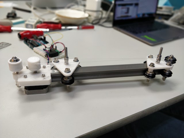
Building Process : Common parts with Dilijian Lab
- Our common parts of 1-axis linear between in Dilijan lab and in Kannai lab
- which are 3d printable parts
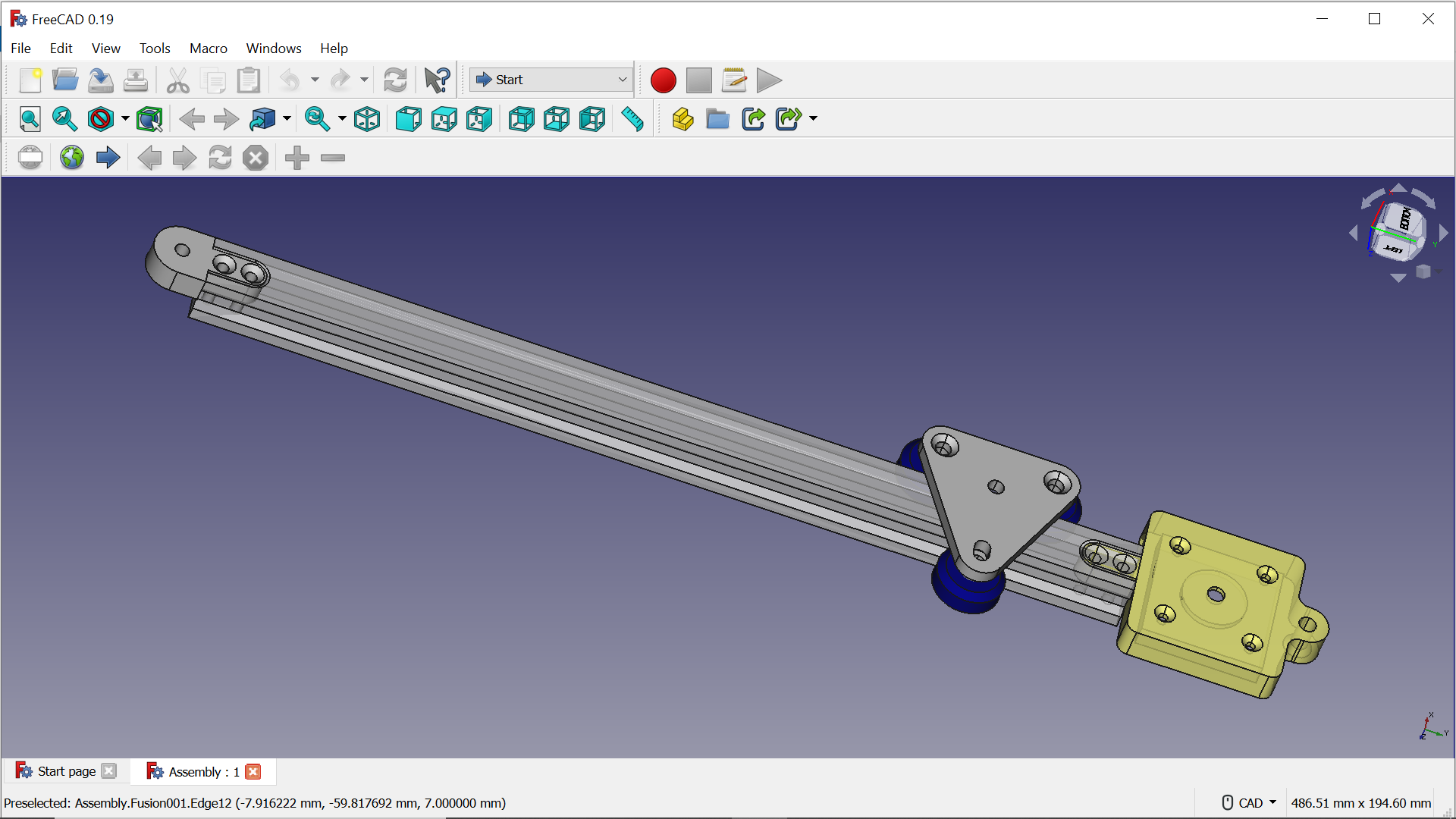
- We usedCommon axis parts by 3d printer
Extrusion Rail (Meshed)_250mm.stl
Carrier with ribs (Meshed).stl
Due to the size limitation of the 3D printer
Extrusion rails only 280mm → 250mm
Transform 3d data to g-code by Cura
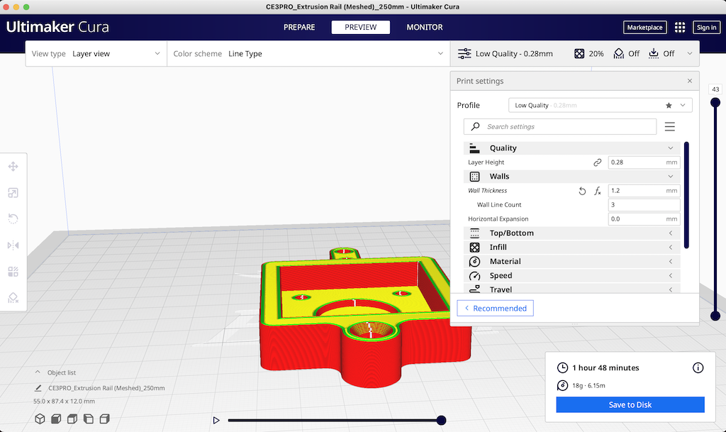
Low quality
Walls Wallthickness 1.2mm
Infill 20% cubic
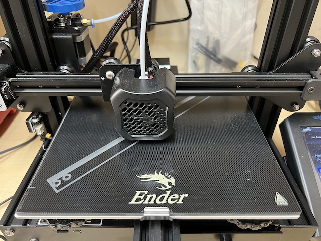
- 3D printed to make parts by Ender
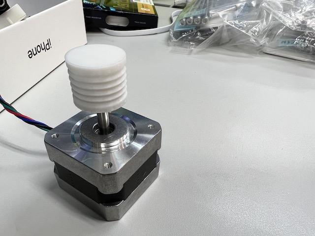
- stepper motor
We decided to use this stepper motor
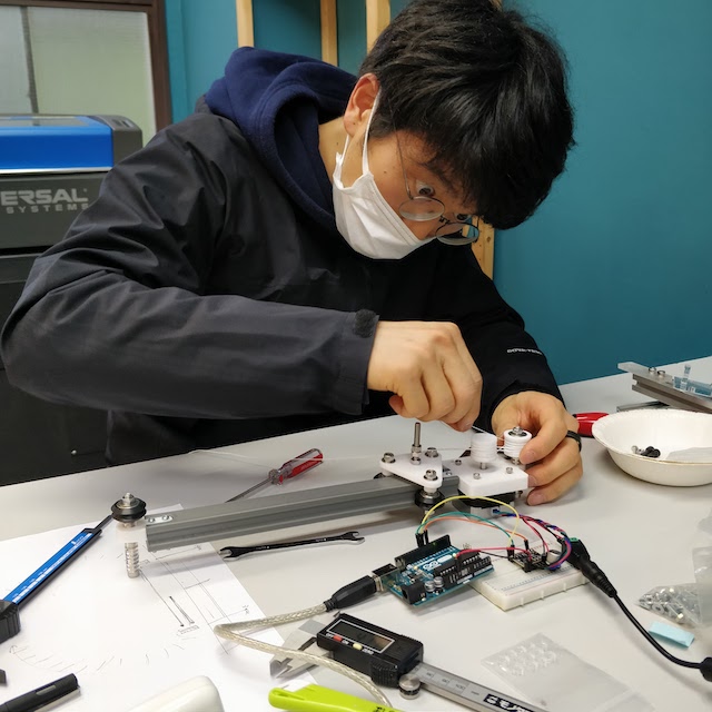
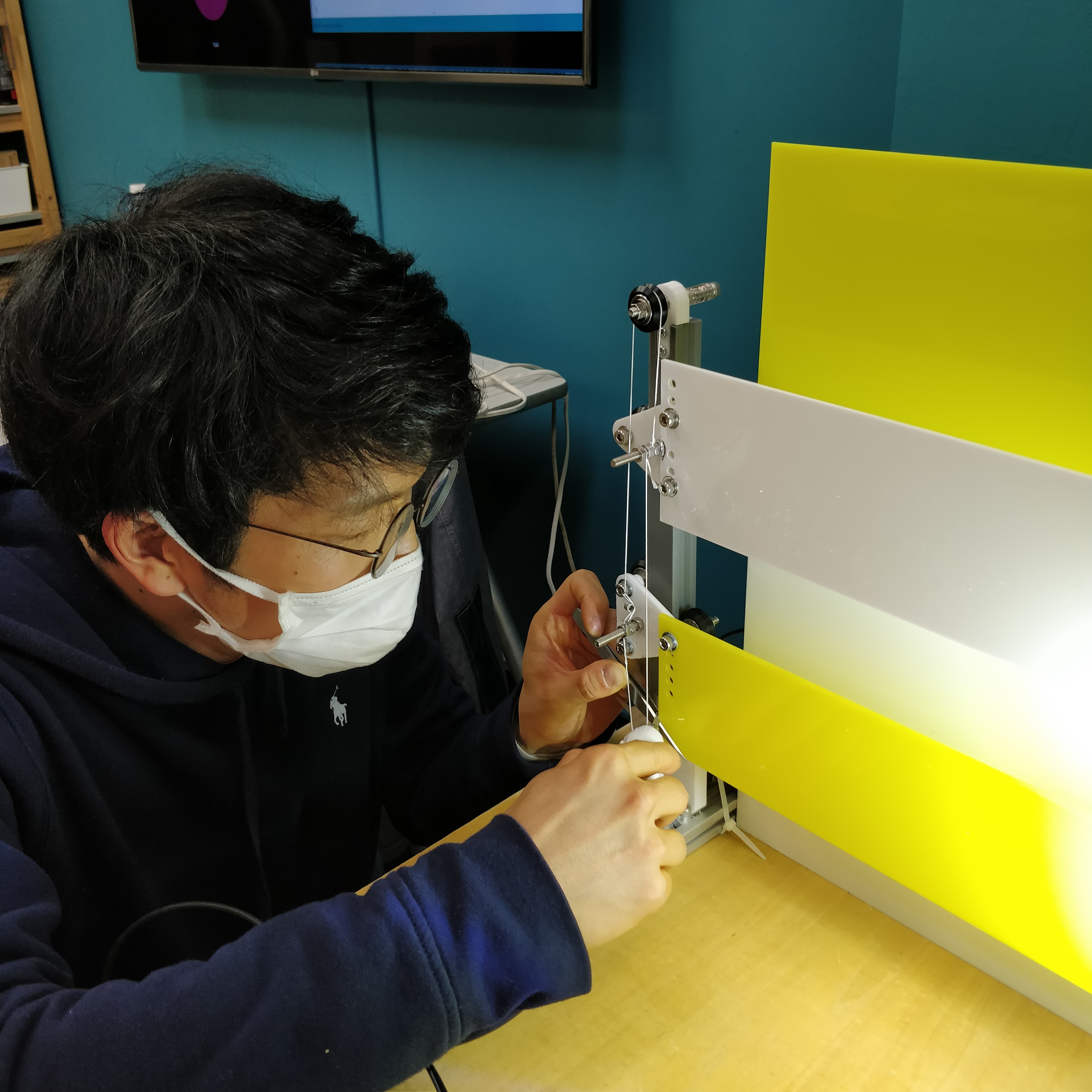
- Assembling
The kite string was wired to create the mechanism carefully.
- finish to make the common parts with Dilijan Lab
- Moving Test
Programming
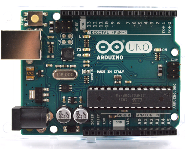
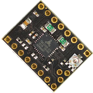
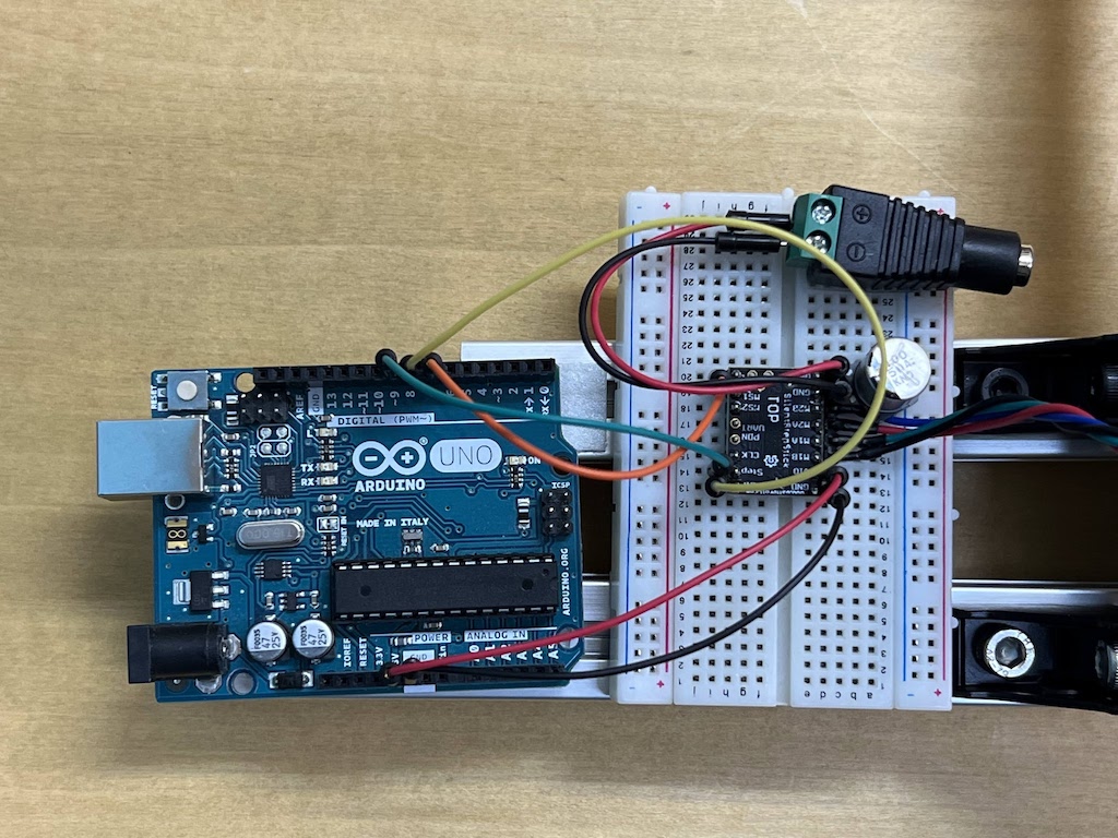
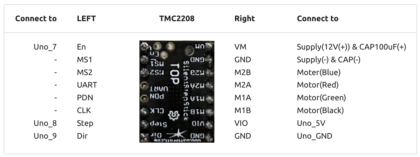
We decided to use Arduino Uno to control the move of the stepper motor. To use it, I connected Arduino Uno to Stepper Motor Driver TMC2208 refering to this Kannai Lab’s instruction Page.
Arduino uno
Stepper motor Driver TMC 2208
Connection
Test 1 : Move to 1 direction
Ref. GitHub project page
Download TMC220X.ino from here
/*
  SilentStepStick TMC2208/TMC2209 Example
  Rsense: 0.11 Ohm
  Other examples/libraries can be found here:
  https://github.com/teemuatlut/TMCStepper
  https://github.com/trinamic/TMC-API
  https://github.com/manoukianv/TMC2208Pilot
  Example source code free to use.
  Further information: https://learn.watterott.com/license/
*/

// Note: You also have to connect GND, 5V/VIO and VM.
//       A connection diagram can be found in the schematics.
#define EN_PIN    7 //enable (CFG6)
#define DIR_PIN   8 //direction
#define STEP_PIN  9 //step

void setup()
{
  //set pin modes
  pinMode(EN_PIN, OUTPUT);
  digitalWrite(EN_PIN, HIGH); //deactivate driver (LOW active)
  pinMode(DIR_PIN, OUTPUT);
  digitalWrite(DIR_PIN, LOW); //LOW to CCW
  //digitalWrite(DIR_PIN, HIGH); //HIGH to CW
  pinMode(STEP_PIN, OUTPUT);
  digitalWrite(STEP_PIN, LOW);

  digitalWrite(EN_PIN, LOW); //activate driver
}

void loop()
{
  //make steps
  digitalWrite(STEP_PIN, HIGH);
  delay(2);
  digitalWrite(STEP_PIN, LOW);
  delay(2);
}
It worked well.
Test 2 : Move back and forth
arrange code
/*
  SilentStepStick TMC2208/TMC2209 Example
  Rsense: 0.11 Ohm
  Other examples/libraries can be found here:
  https://github.com/teemuatlut/TMCStepper
  https://github.com/trinamic/TMC-API
  https://github.com/manoukianv/TMC2208Pilot
  Example source code free to use.
  Further information: https://learn.watterott.com/license/
*/

// Note: You also have to connect GND, 5V/VIO and VM.
//       A connection diagram can be found in the schematics.
#define EN_PIN    7 //enable (CFG6)
#define DIR_PIN   8 //direction
#define STEP_PIN  9 //step

void setup()
{
  //set pin modes
  pinMode(EN_PIN, OUTPUT);
  digitalWrite(EN_PIN, HIGH); //deactivate driver (LOW active)

  pinMode(DIR_PIN, OUTPUT);
  //digitalWrite(DIR_PIN, LOW); //LOW to CCW
  digitalWrite(DIR_PIN, HIGH); //HIGH to CW

  pinMode(STEP_PIN, OUTPUT);
  digitalWrite(STEP_PIN, LOW);

  digitalWrite(EN_PIN, LOW); //activate driver
}

void loop()
{

  for (int i = 0; i <= 255; i++){
  digitalWrite(DIR_PIN, LOW); //LOW to CCW
  //make steps
  digitalWrite(STEP_PIN, HIGH);
  delay(2);
  digitalWrite(STEP_PIN, LOW);
  delay(2);
  }

 for (int i = 0; i <= 255; i++){
  digitalWrite(DIR_PIN, HIGH); //HIGH to CW
  //make steps
  digitalWrite(STEP_PIN, HIGH);
  delay(2);
  digitalWrite(STEP_PIN, LOW);
  delay(2);
  }


}
Test 3 : Experiment about how to proceed
Since the time to turn the axis = the width of movement is controlled by changing the value of i, I set the value of i appropriately and observed how many centimeters the axis moved.
/*
  SilentStepStick TMC2208/TMC2209 Example
  Rsense: 0.11 Ohm
  Other examples/libraries can be found here:
  https://github.com/teemuatlut/TMCStepper
  https://github.com/trinamic/TMC-API
  https://github.com/manoukianv/TMC2208Pilot
  Example source code free to use.
  Further information: https://learn.watterott.com/license/
*/

// Note: You also have to connect GND, 5V/VIO and VM.
//       A connection diagram can be found in the schematics.
#define EN_PIN    7 //enable (CFG6)
#define DIR_PIN   8 //direction
#define STEP_PIN  9 //step

void setup()
{
  //set pin modes
  pinMode(EN_PIN, OUTPUT);
  digitalWrite(EN_PIN, HIGH); //deactivate driver (LOW active)

  pinMode(DIR_PIN, OUTPUT);
  //digitalWrite(DIR_PIN, LOW); //LOW to CCW
  digitalWrite(DIR_PIN, HIGH); //HIGH to CW

  pinMode(STEP_PIN, OUTPUT);
  digitalWrite(STEP_PIN, LOW);

  digitalWrite(EN_PIN, LOW); //activate driver
}

void loop()
{

  delay(5000);

  for (int i = 0; i <= 1600; i++){
  digitalWrite(DIR_PIN, LOW); //LOW to CCW
  //make steps
  digitalWrite(STEP_PIN, HIGH);
  delay(2);
  digitalWrite(STEP_PIN, LOW);
  delay(2);

  }

  delay(5000);

}
When i=500, it moved 20.8 mm.
i=500 *4 millsec =2 sec
Since moving 1.8 degrees is 1/8 microsteps, I calculated how many times it should be repeated
1.8 / 8 * i [steps] = 360
i = 1600 [steps] should be one revolution. The diameter of the gear is 20.6 mm, so the circumference is 3.14 * 20.6 mm * 1 round = 64.684 mm
When we actually measured the distance moved, the distance moved was exactly as it should be. So to count “1 sec”, I set “i=800”.
Final code : Programs that measure a minute
/*
  SilentStepStick TMC2208/TMC2209 Example
  Rsense: 0.11 Ohm
  Other examples/libraries can be found here:
  https://github.com/teemuatlut/TMCStepper
  https://github.com/trinamic/TMC-API
  https://github.com/manoukianv/TMC2208Pilot
  Example source code free to use.
  Further information: https://learn.watterott.com/license/
*/

// Note: You also have to connect GND, 5V/VIO and VM.
//       A connection diagram can be found in the schematics.
#define EN_PIN    7 //enable (CFG6)
#define DIR_PIN   8 //direction
#define STEP_PIN  9 //step

void setup()
{
  //set pin modes
  pinMode(EN_PIN, OUTPUT);
  digitalWrite(EN_PIN, HIGH); //deactivate driver (LOW active)

  pinMode(DIR_PIN, OUTPUT);
  digitalWrite(DIR_PIN, LOW); //LOW to CCW
  //digitalWrite(DIR_PIN, HIGH); //HIGH to CW

  pinMode(STEP_PIN, OUTPUT);
  digitalWrite(STEP_PIN, LOW);

  digitalWrite(EN_PIN, LOW); //activate driver
}

void loop()
{

 delay(3000);

  for (int i = 0; i <= 800; i++){  // center to xx cm in 30 sec

  digitalWrite(DIR_PIN, HIGH); //LOW to CCW
  //make steps
  digitalWrite(STEP_PIN, HIGH);
  delay(2);
  digitalWrite(STEP_PIN, LOW);
  delay(73);

  }

  delay(3000);

}
Original Parts in Kannai
What to create with a mechanism that measures one minute.
- Ideation
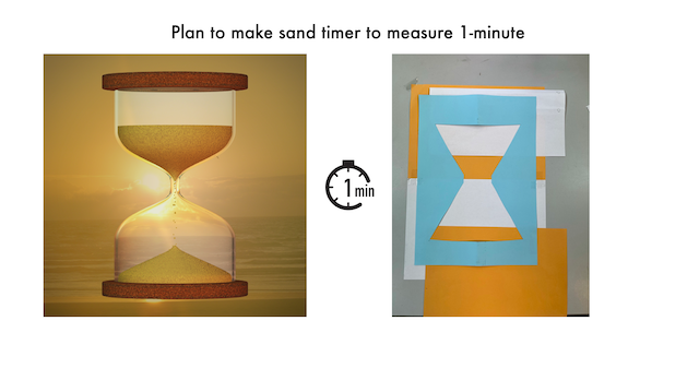
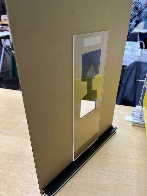
- Prototype of sand timer by 1-axis linear
Prototype the use of two moving boards to see if an hourglass movement can be achieved.
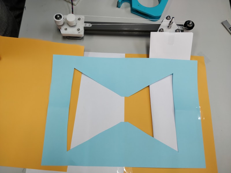
- Finish to make the structure of vertical 1-axis linear
- embed programming
1 minute count programme
/*
  SilentStepStick TMC2208/TMC2209 Example
  Rsense: 0.11 Ohm
  Other examples/libraries can be found here:
  https://github.com/teemuatlut/TMCStepper
  https://github.com/trinamic/TMC-API
  https://github.com/manoukianv/TMC2208Pilot
  Example source code free to use.
  Further information: https://learn.watterott.com/license/
*/

// Note: You also have to connect GND, 5V/VIO and VM.
//       A connection diagram can be found in the schematics.
#define EN_PIN    7 //enable (CFG6)
#define DIR_PIN   8 //direction
#define STEP_PIN  9 //step

void setup()
{
  //set pin modes
  pinMode(EN_PIN, OUTPUT);
  digitalWrite(EN_PIN, HIGH); //deactivate driver (LOW active)

  pinMode(DIR_PIN, OUTPUT);
  digitalWrite(DIR_PIN, LOW); //LOW to CCW
  //digitalWrite(DIR_PIN, HIGH); //HIGH to CW

  pinMode(STEP_PIN, OUTPUT);
  digitalWrite(STEP_PIN, LOW);

  digitalWrite(EN_PIN, LOW); //activate driver
}

void loop()
{

 delay(3000);

  for (int i = 0; i <= 800; i++){  // center to xx cm in 30 sec

  digitalWrite(DIR_PIN, HIGH); //LOW to CCW
  //make steps
  digitalWrite(STEP_PIN, HIGH);
  delay(2);
  digitalWrite(STEP_PIN, LOW);
  delay(73);

  }

  delay(3000);

}
-
cut acrylic boards by laser cutter and set up them
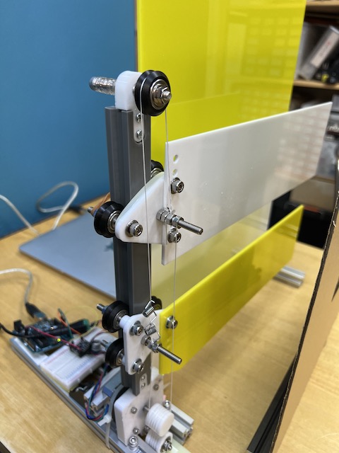
mechanism of sand timer.
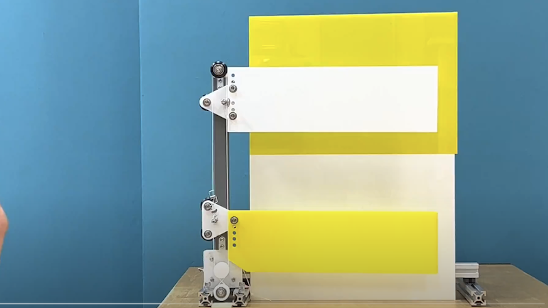
- mechanism test
-
cut cardboard by laser cutter and put the acliryc board on the cardboard
-
hero shot