Dilijan and Kannai, Machine Building Group Site
Project name
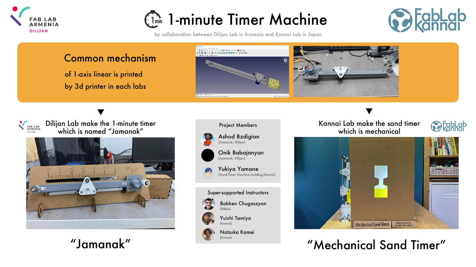
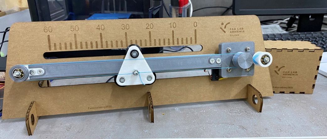
Jamanak
Slide and Video
Members

| Fablab Armenia Dilijan | FabLab Kannai, Japan | |
|---|---|---|
| Student | Ashod Bzdigian Onik Babajanyan |
Yukiya Yamane |
| Instructor | Babken hugaszyan | Yuichi Tamiya Natsuka Kamei |
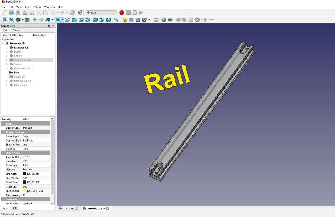
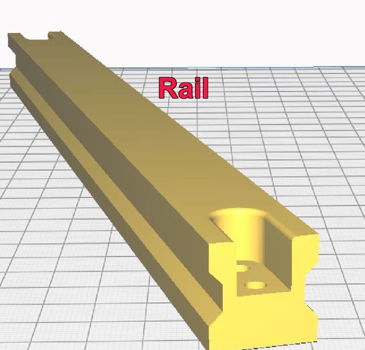
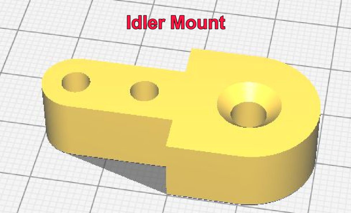
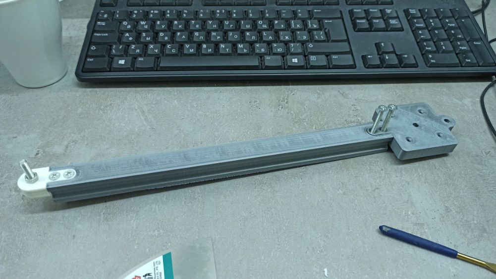
3D printed rail to make it modular

Story
- 3D printed Urunbu based 1 axis machine in Instructors boot camp by Babken
- Dilijan redesigned it in modular
- Dilijan made Stopwatch with it and share files
- Kannai printed out and assembled the same machine
- Kannai got inspiration from Dilijan’s Stopwatch machine and made a machine of measuring the time by different way with it.
Stopwatch machine (Dilijan’s machine)
Files
Mechanical design
The week assignment is one of the most important ones, it is divided by two task each one with different group and individual assignments. You can check the machine in its totallity clicking on this link
1. Tasks
1.1 Mechanical Design (part 1 of 2)
Group assignment:
Design a machine that includes mechanism + actuation + automation
Build the mechanical parts and operate it manually.
Document the group project
Individual assignment:
Document your individual contribution.
1.2 Machine Design (part 2 of 2)
Group assignment:
Actuate and automate your machine.
Document the group project
Individual assignment:
Document your individual contribution.
2. Briefing
We decided to collaborate with Kannai, Japan for this assignment.
First we created a group in Mattermost to keep in touch and to upload different content for us.
We started dividing the time with a schedule, so we would have a tidy process.
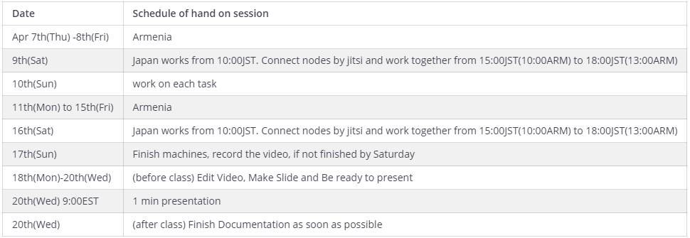
And as well, we had regular meetingsx
3. Process
So we started making some ideas on how can we design the machine.
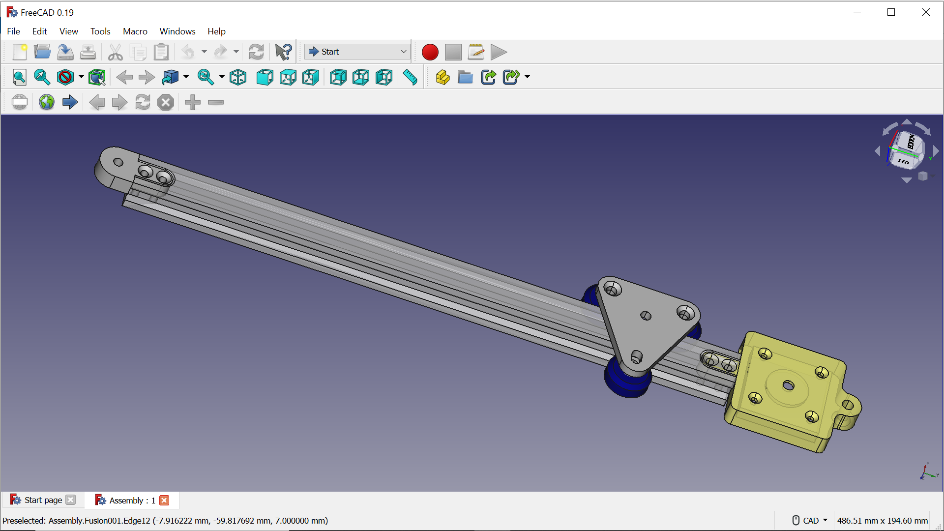
We decided to use Babken’s Urunbu machine from 2022 bootcamp in Finland. So we downloaded the files that he used and we began to work in Freecad using his design but with modifications.
This is the original machine:
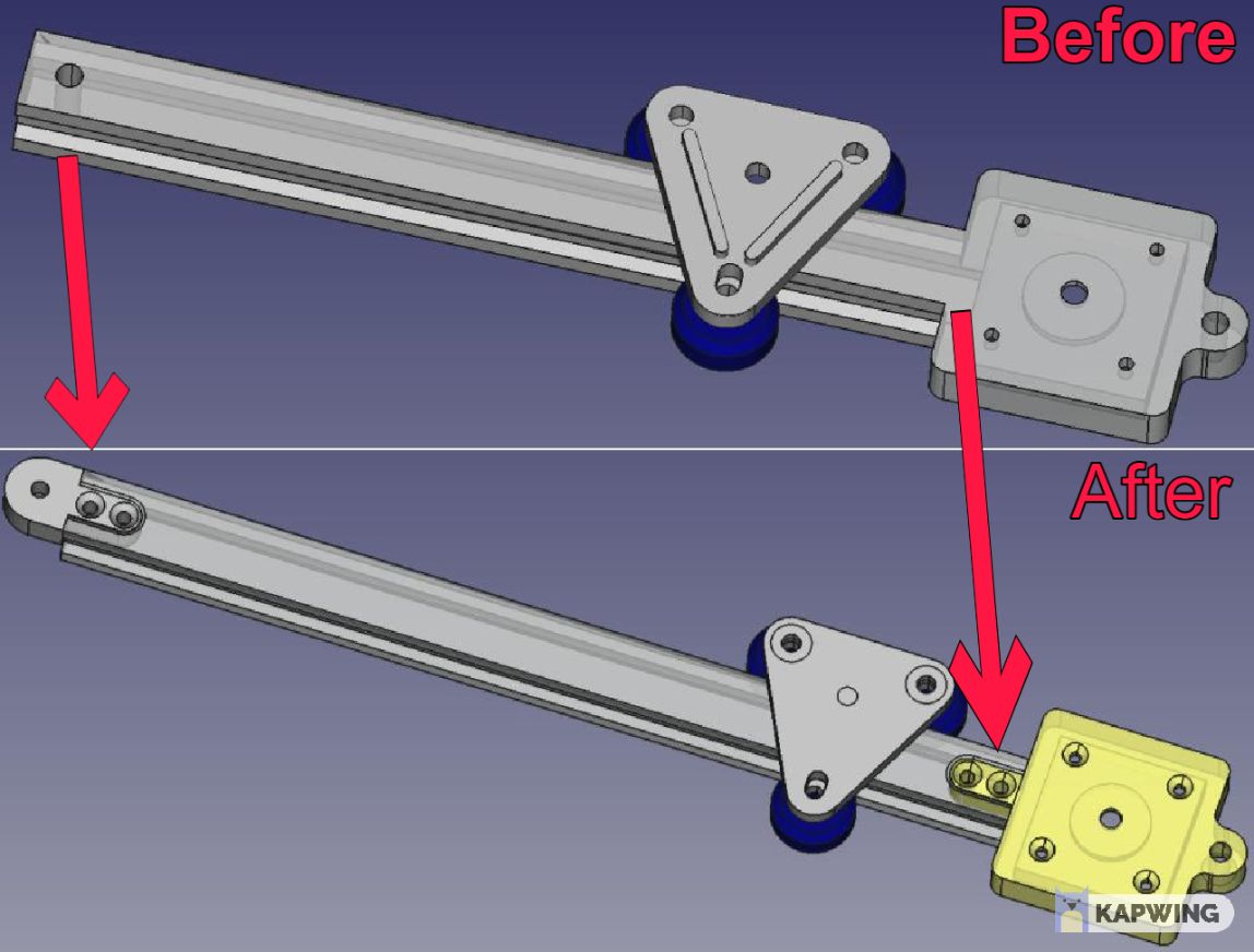
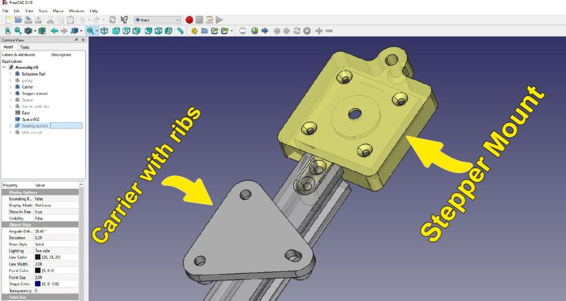
As you can see, the holes from the left were replaced, making the machine to be modular now. This means, that it can be assembled with an increasing number of identical parts.
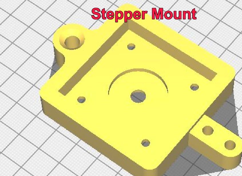
As well, we added some holes to the printing stepper mount, because before it was attached by joints. Now it will be attached by screws.
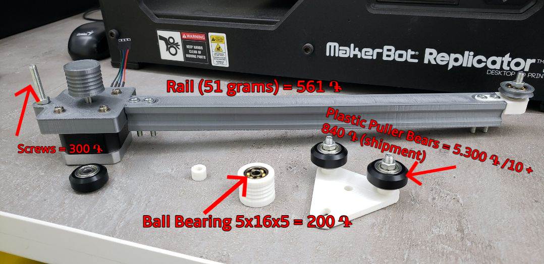
| These are the components that we used from the original: |
|---|
   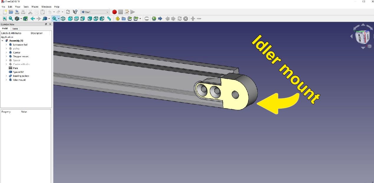 |
Note
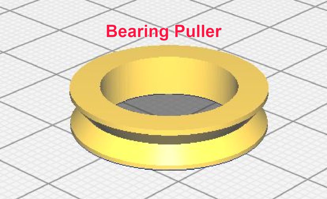
Of course that we bought the Plastic Pulling Bears. (In the next section you will find the cost of the materials).
Also, we used some components from Quentin’s UrumbotXY
| So far these are all the elements that we used: |
|---|
       |
| One Plastic Puller Bear costs 530֏, as we used three of them then the total cost is 1590֏ |
| The Ball Bearing 5d16x5 cost 200֏, as we used three of them the total cost is 600֏ |
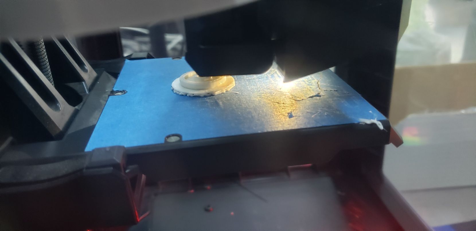
3.1 Printing
The printing process was a bit hard for a reason that we will explain in the ERROR section.
But so far it was a beautfil experience.
4. BOM
In this section you will have an idea of the cost of this machine:
Note
From the date that this documentation is being written up, the currency exchange from dolar to dram is:

1kg of plastic filaments costs 11.000 drams.
| After every print, we measure the weight of the components: |
|---|
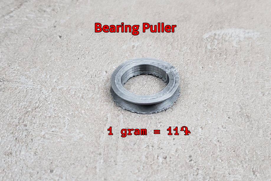 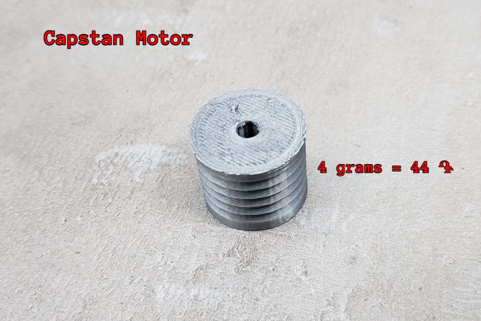 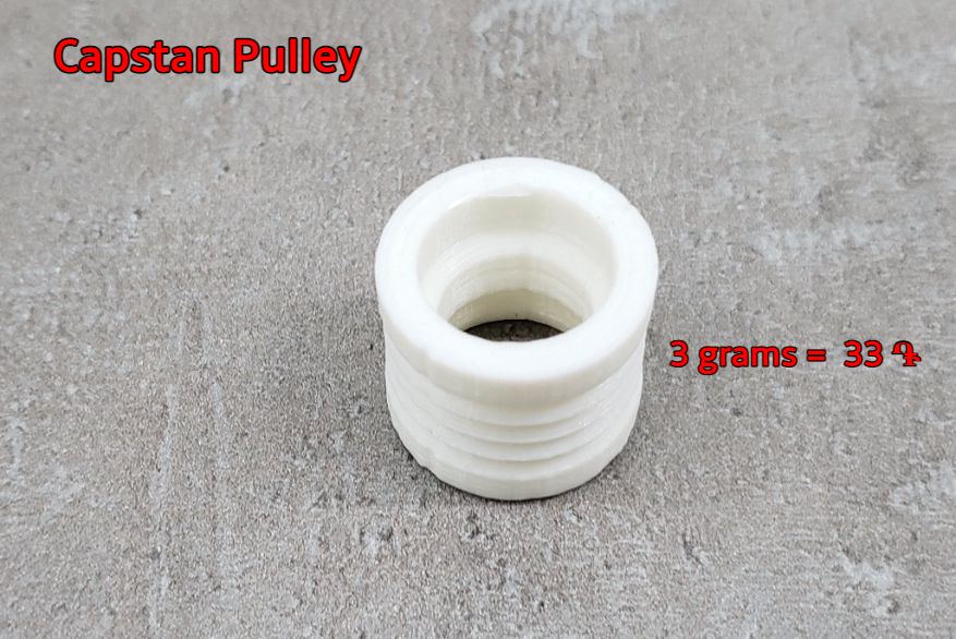 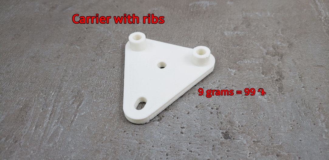 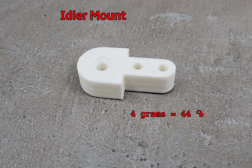 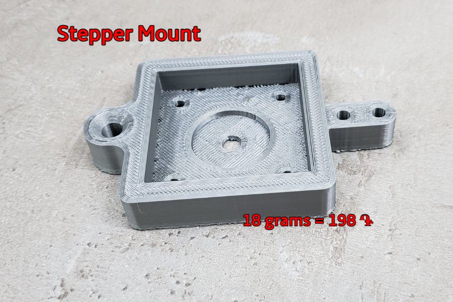  |
| As well, Babken bought a fishing line that cost 10.384֏ + shipment(200֏) |
|---|
 |
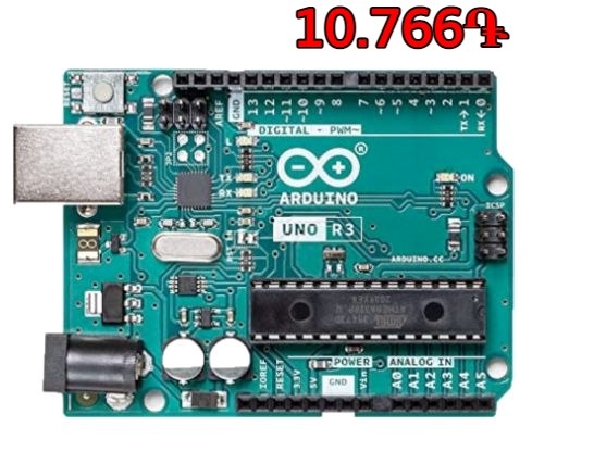
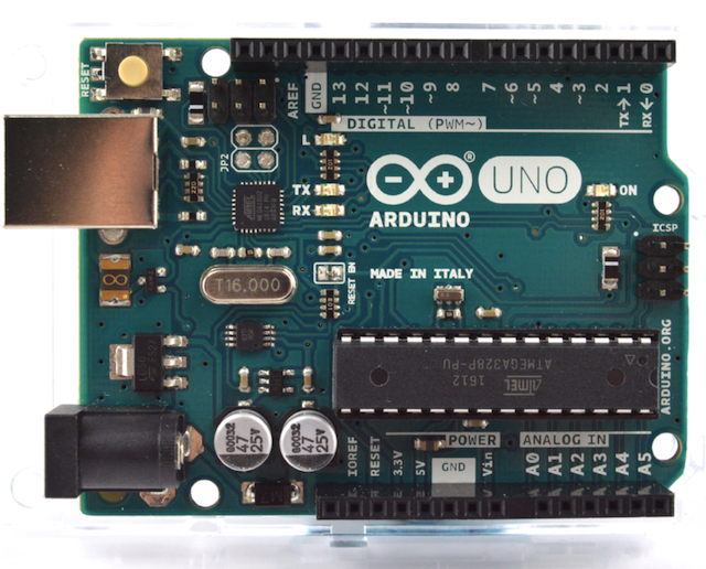
| We used an Arduino UNO that cost 10.766֏ |
|---|
 |
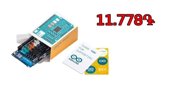
| An Arduino Motor Shield REV3 that cost 11.778֏ |
|---|
 |
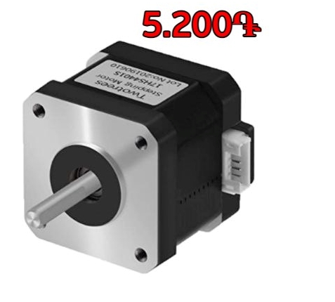
| And a Nema17 Stepper Motor that cost 5.200֏ |
|---|
 |
Total
The total cost in drams is 45.969֏, which in Dollars is: Total cost of the machine: $97,22 (USD)
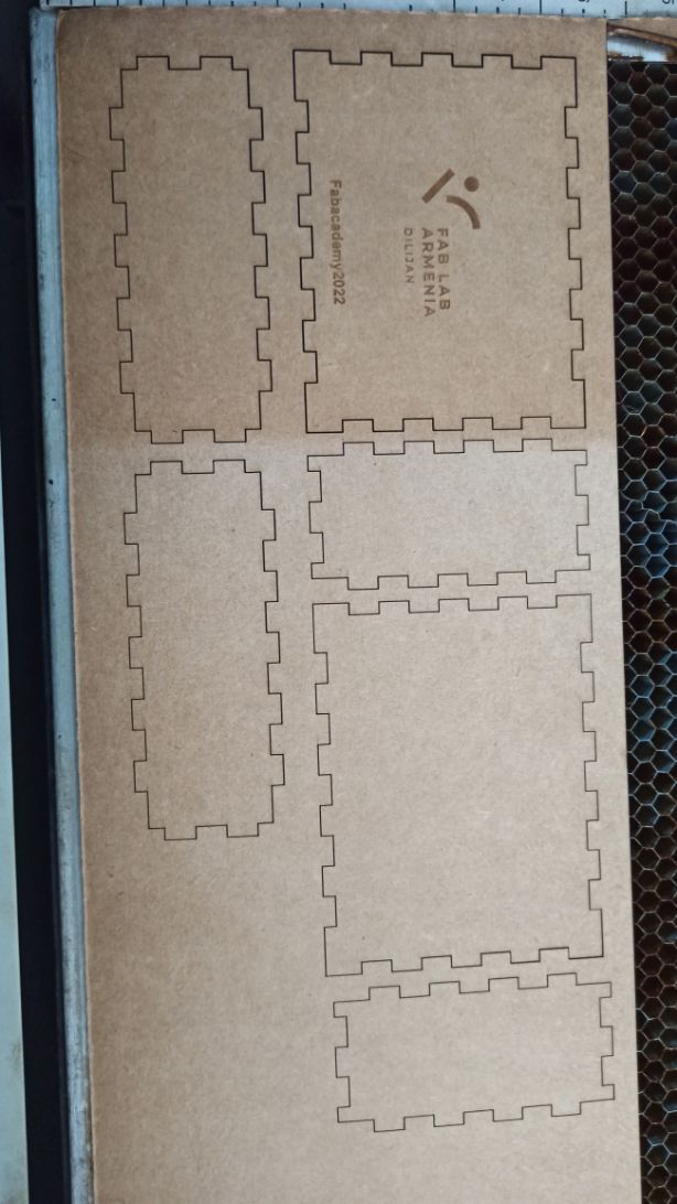
5. Mounting the Machine
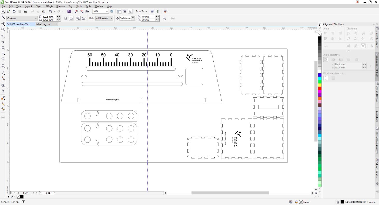
We wanted to create a simple carton case for our machine usign CorelDraw and the laser cut machine.
But…
We had several mistakes while we tried to set up the machine.
5.1 ERRARE HUMANUM EST, SED PERSERVARE DIABOLICUM
Fail 1
So the first mistake that was presented to us, it was with the temperature. Inside of our Fab Lab is a little bit cold, for this reason, the rails that we were doing bent, making it impossible to continue.
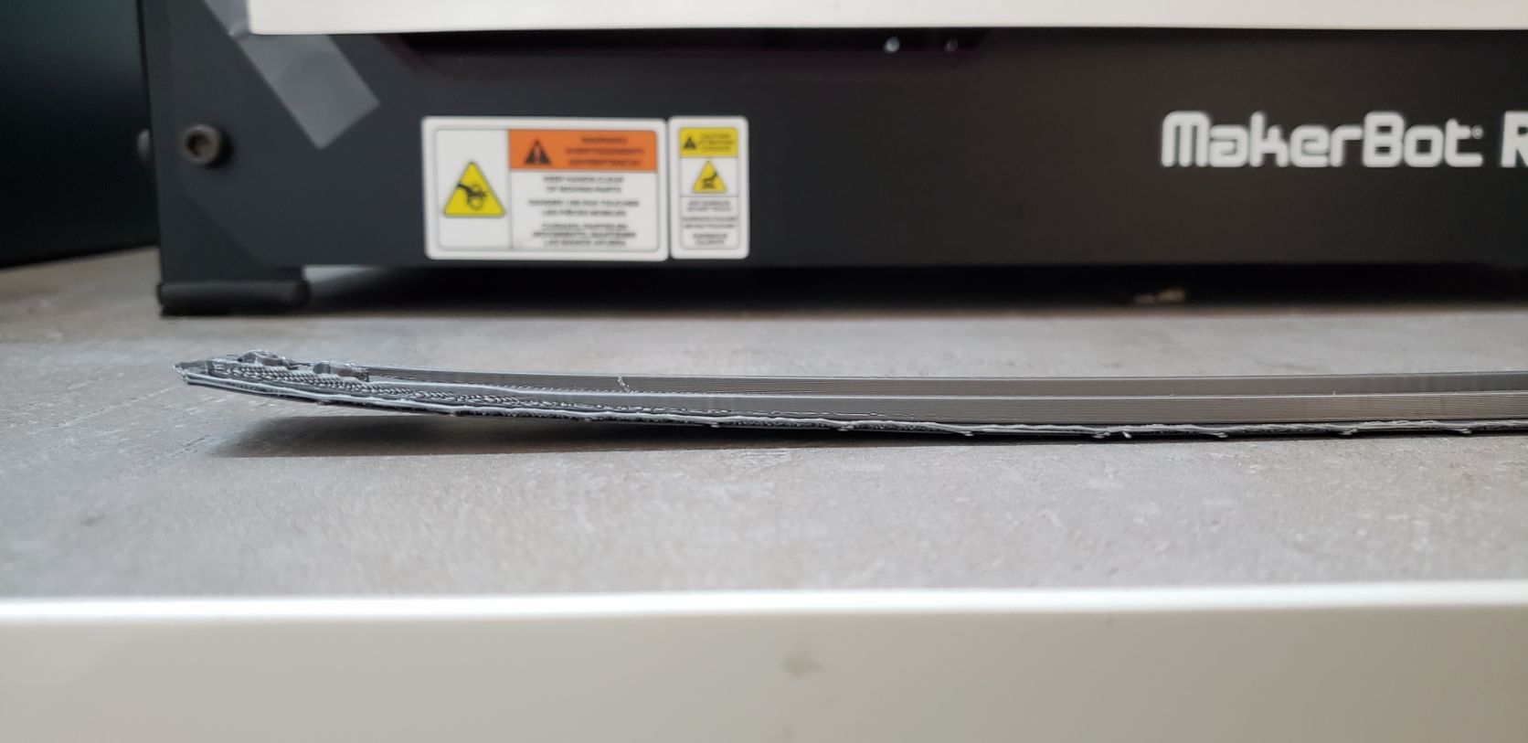
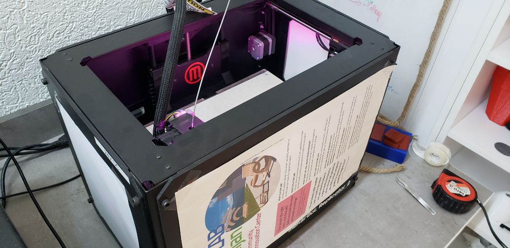
So we made a very “fancy” case to protect the prints from the cold and the wind:
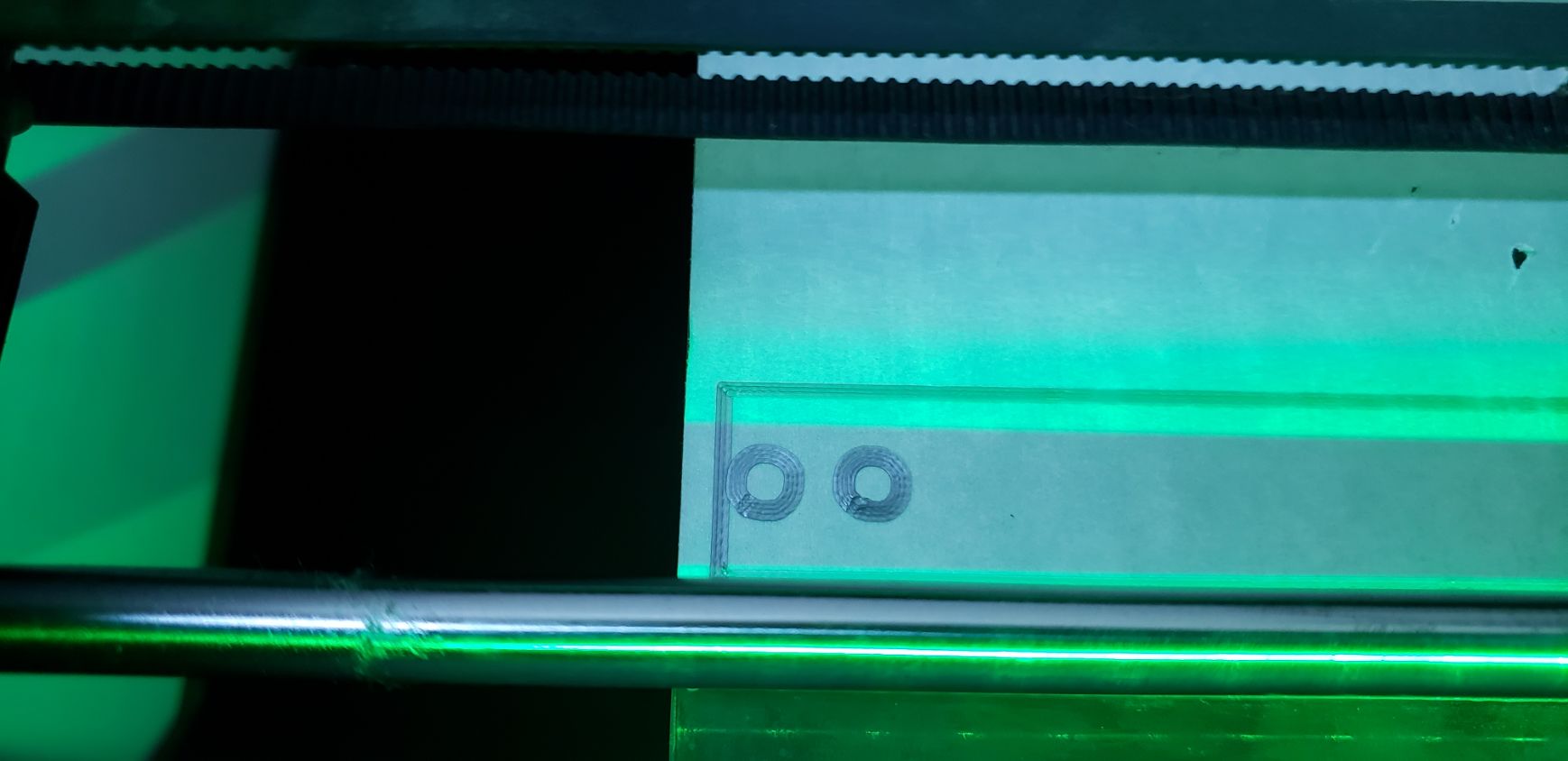
Fail 2
it was the length between the pair of the holes on the left with the right holes.
We still don’t know how (because we measure the distance) this occured.
As you can see, the error was about 1mm or 2mm.
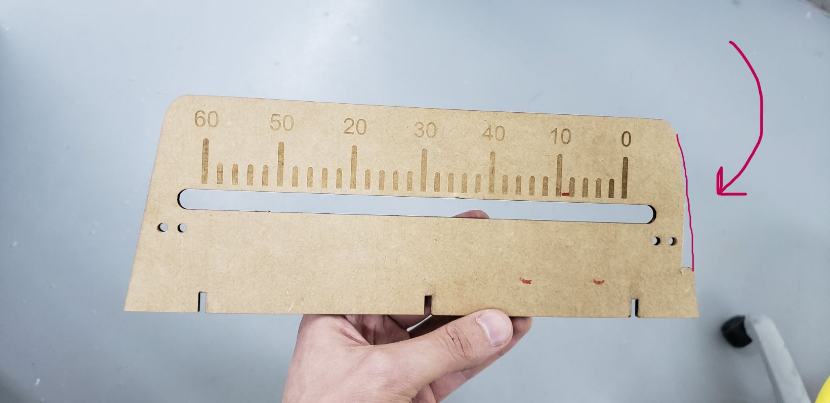
Fail 3
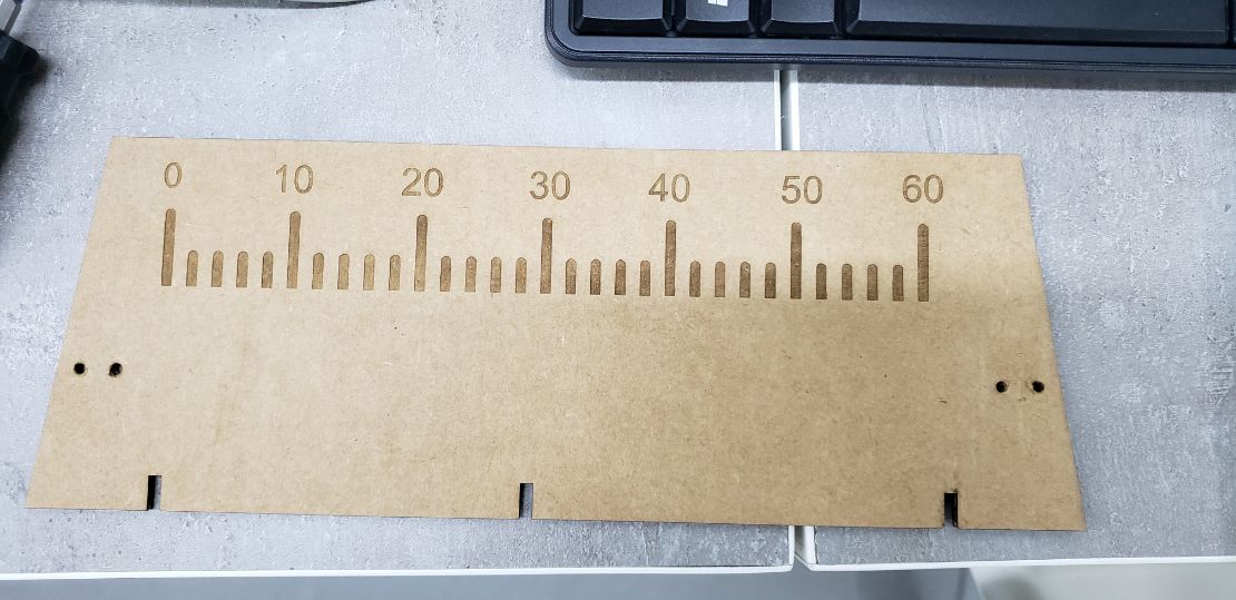
As we finally did the correct length, we realised that our numbers are swapped. We wanted to do a timer that goes to 60 seconds to zero. But this design goes to 0 seconds to 60 seconds:
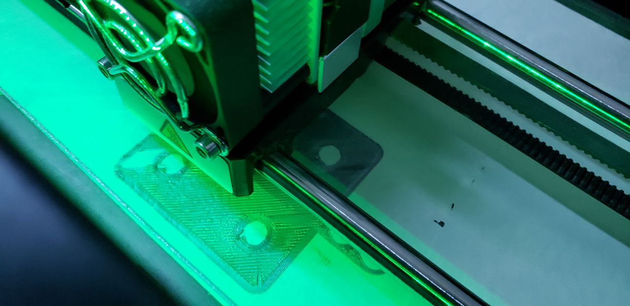
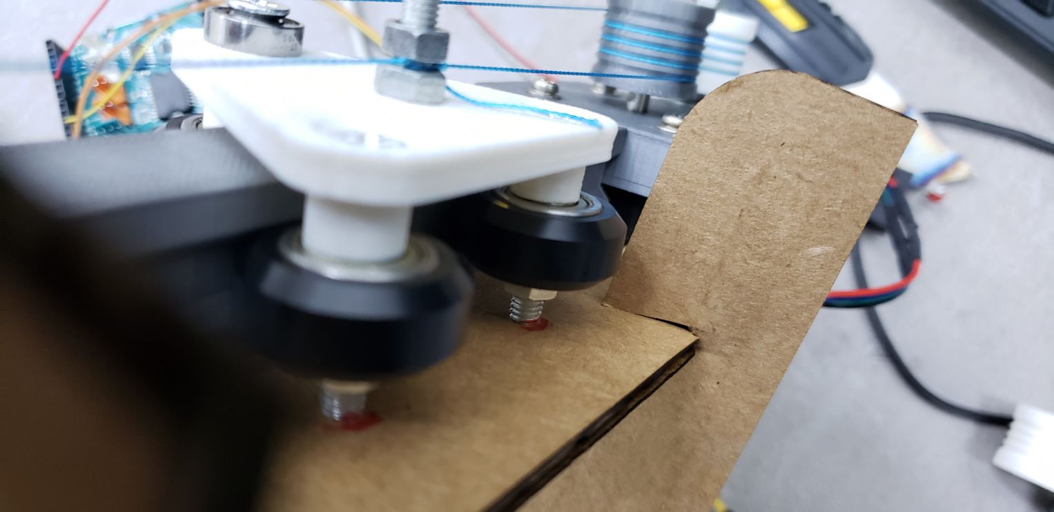
Fail 4
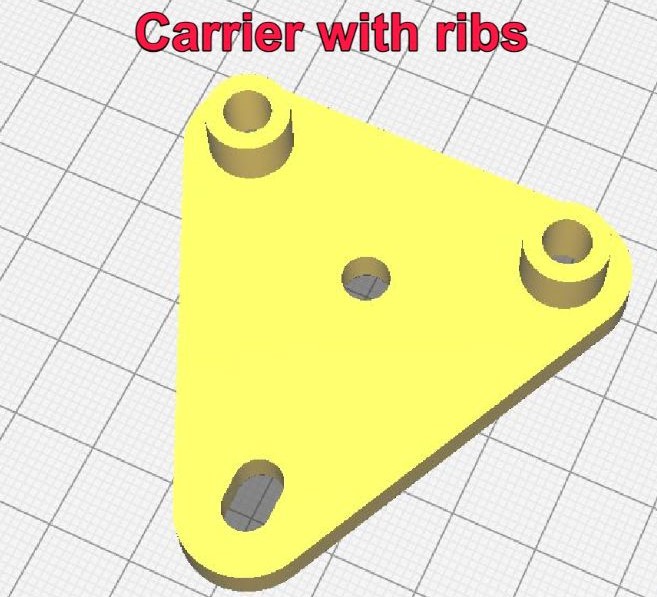
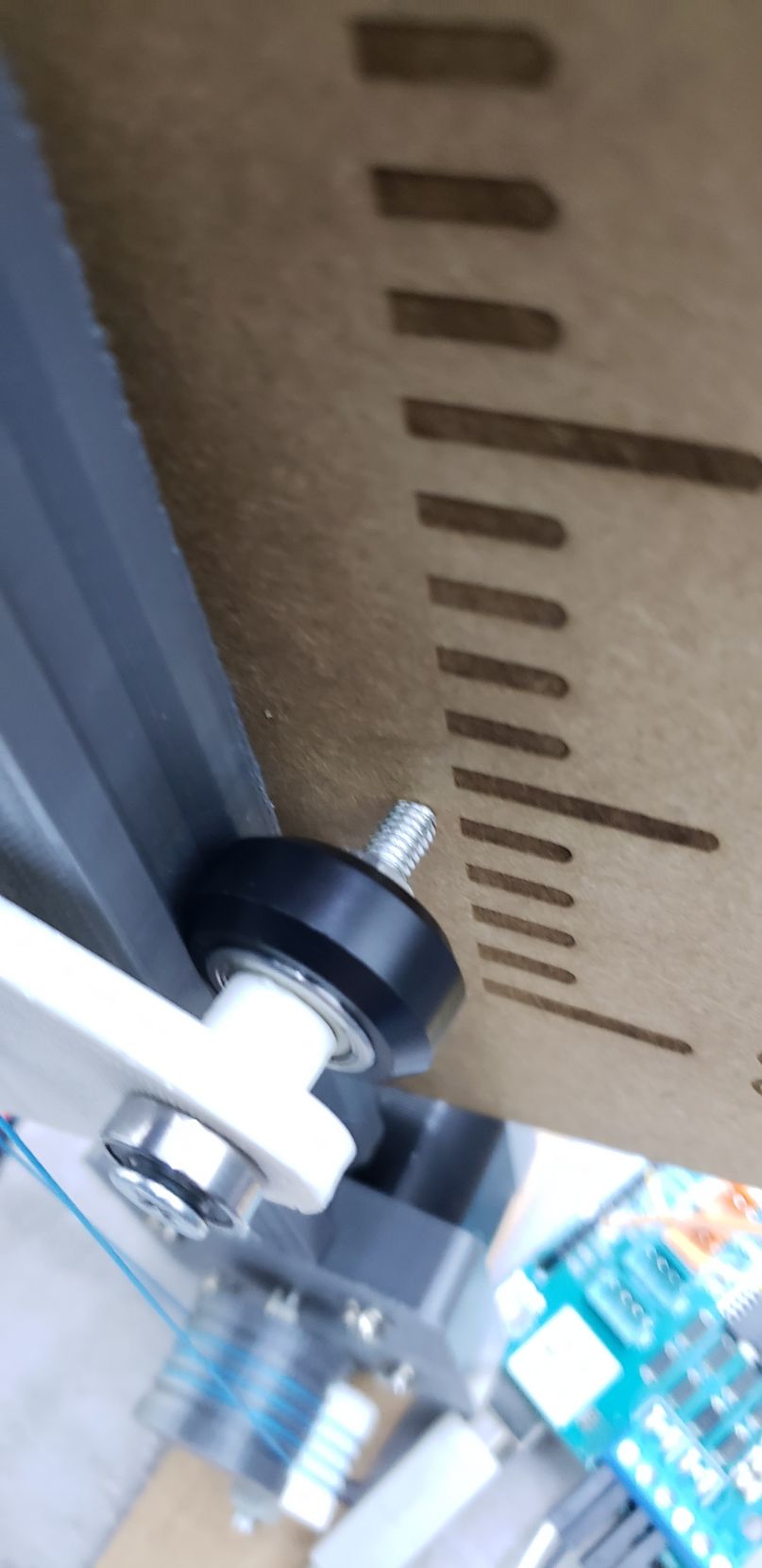
The second mistake that we noticed, was that on the part that goes the top screw of the Carrier with ribs will not advance smoothly, due to the contact between the screw and the carton.
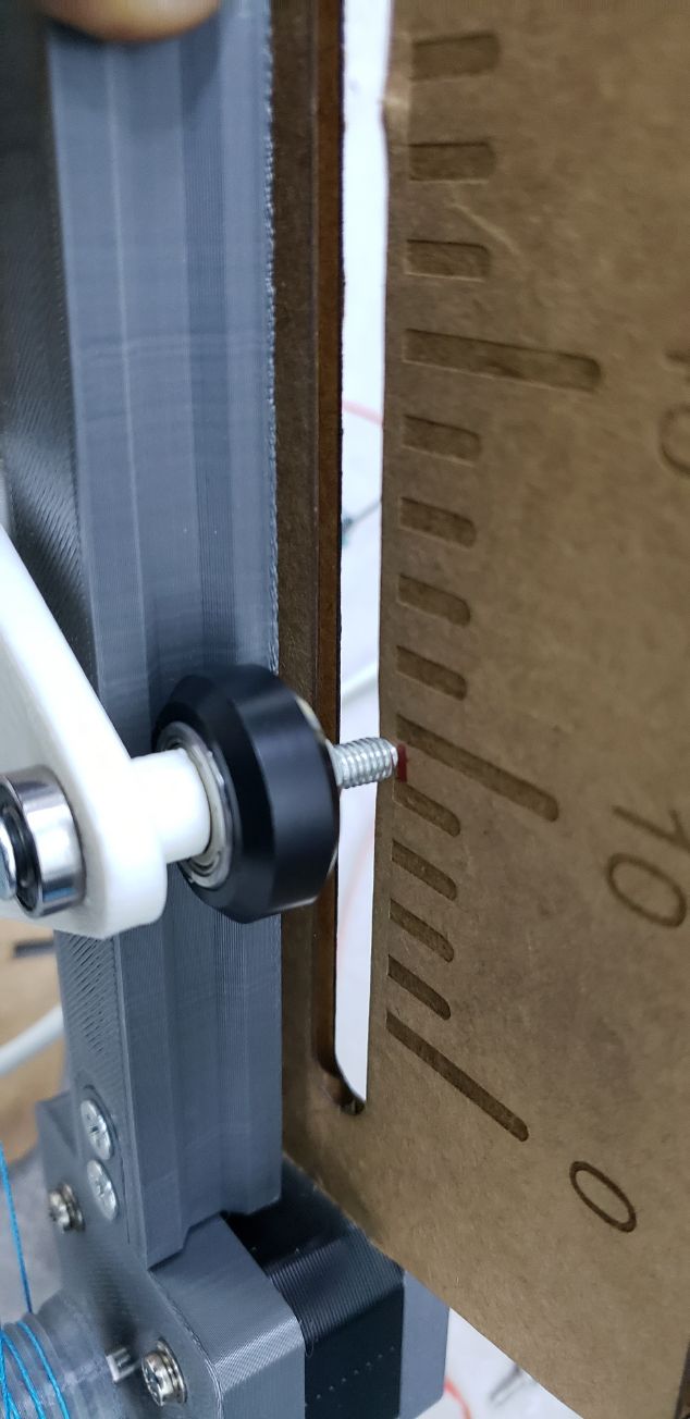
Fail 5
We did a hole, but again, strangely the measure was incorrect. The screw was still touching a part of the carton.
But because of this, we also noticed that we would have to do the same cuts in the carton where the bottom screws are.
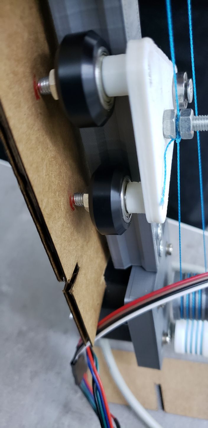
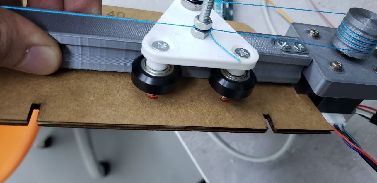
And not only because of the carton, but because of the legs that the design will have.
Fail 6
We had to cut as well the part where the motor goes, as it doesn’t fit that well in the laser cut carton design.
So far this is what we had:
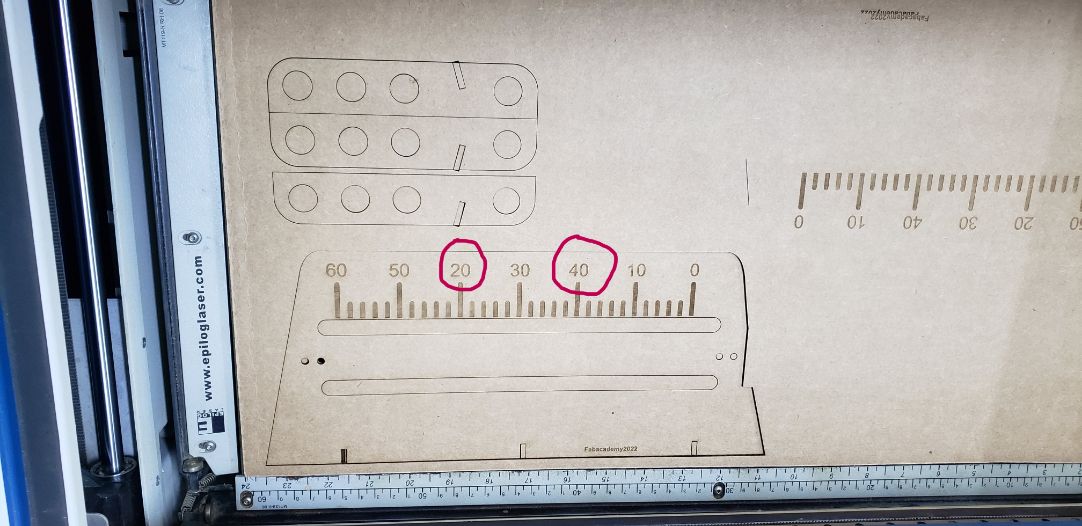
Fail 7
Everything was perfect now, and the design was good, and we actually printed everything.
Until we realise about a tiny mistake.
As we had to change everything, and we even had to move the numbers, accidentaly we put the numbers wrongly.
5.2 Veni, vidi, creatus
To make things tidier, we created a cardboard using a very cool website called MakerCase, that allows people to generate a box. This website is totally customizable, and it allows you to increase the joints, the size and it even gives you the kerf
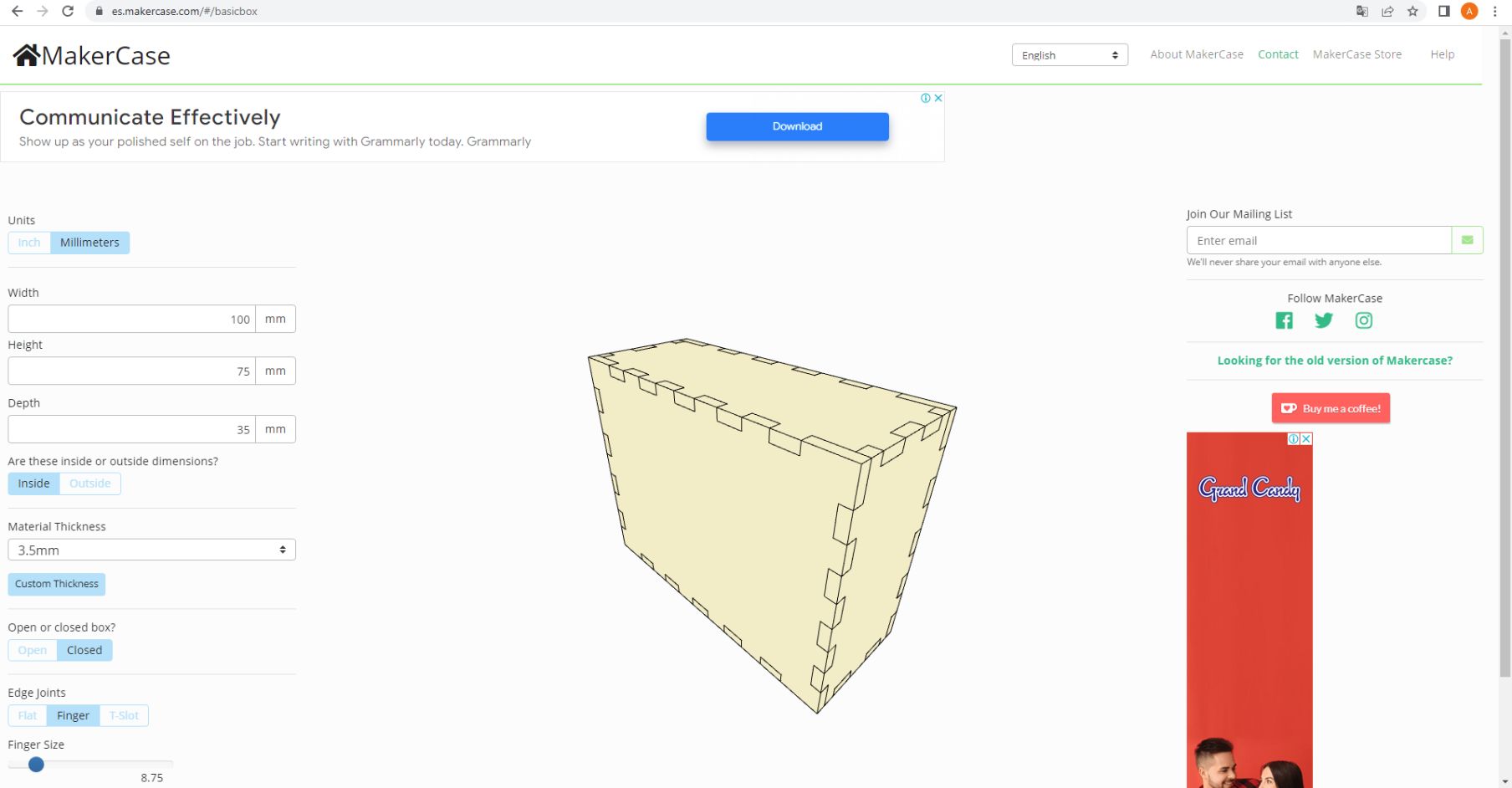
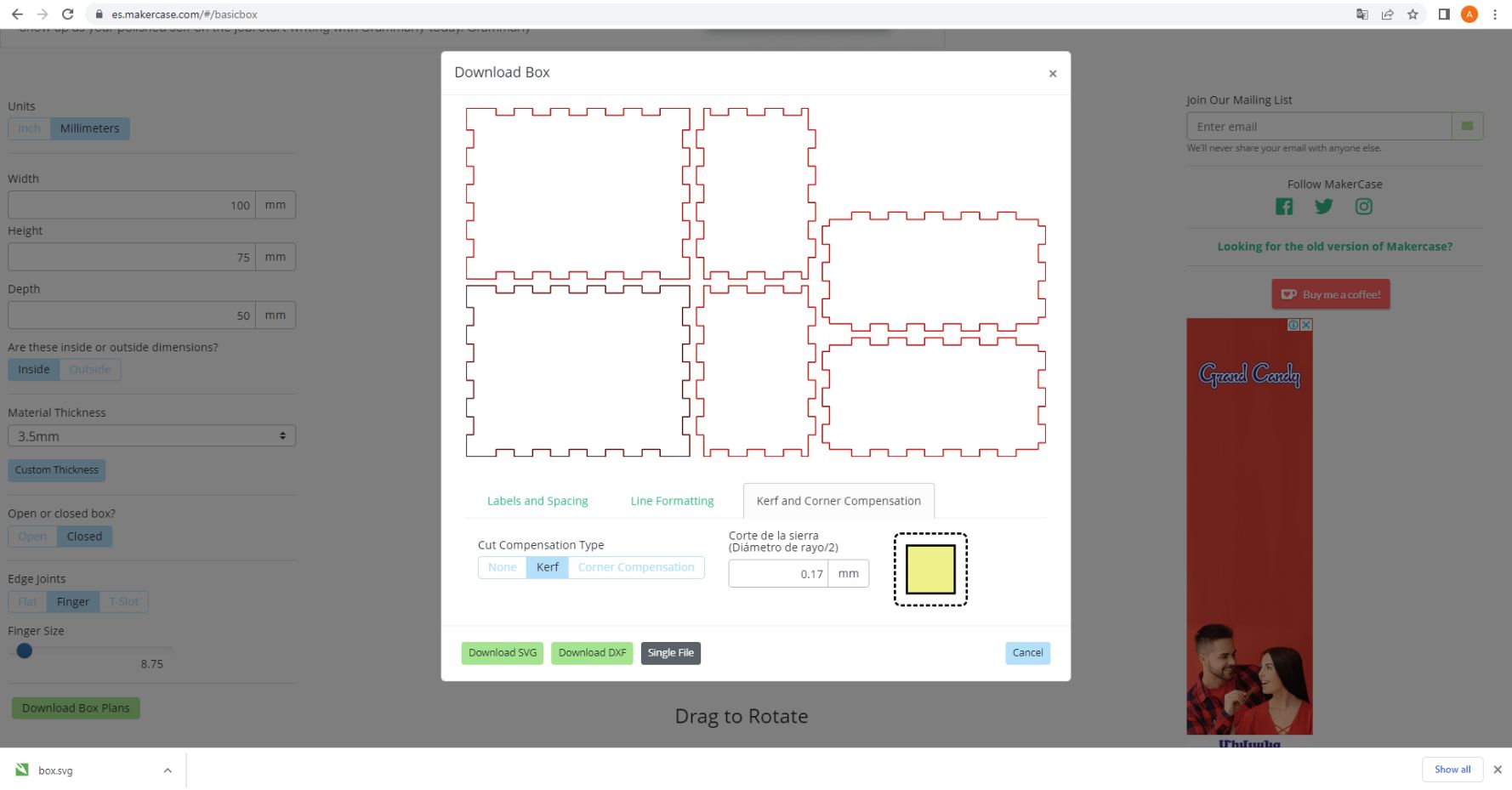
The download file is .svg type.
Note
We had an issue, that whenever that the Carrier with ribs reached the end, the entire machine gently swang to the right (the side where the motor is) beacause of the weight. For this reason we had to separate the legs a little bit one from each other.
As well, we didn’t have to cut anymore a slide of our carton, because what we did, was to create a hole to fit our motor there. It was a success!
After a long path of failures, we got a result like this:
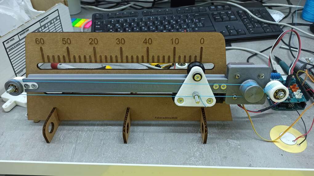
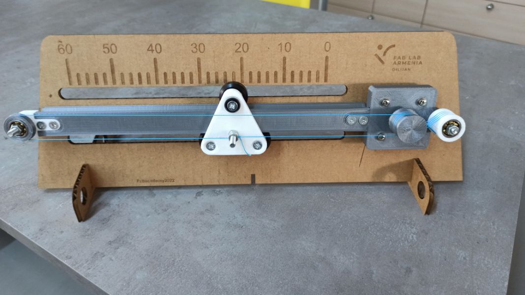
And this is our final machine with the case:
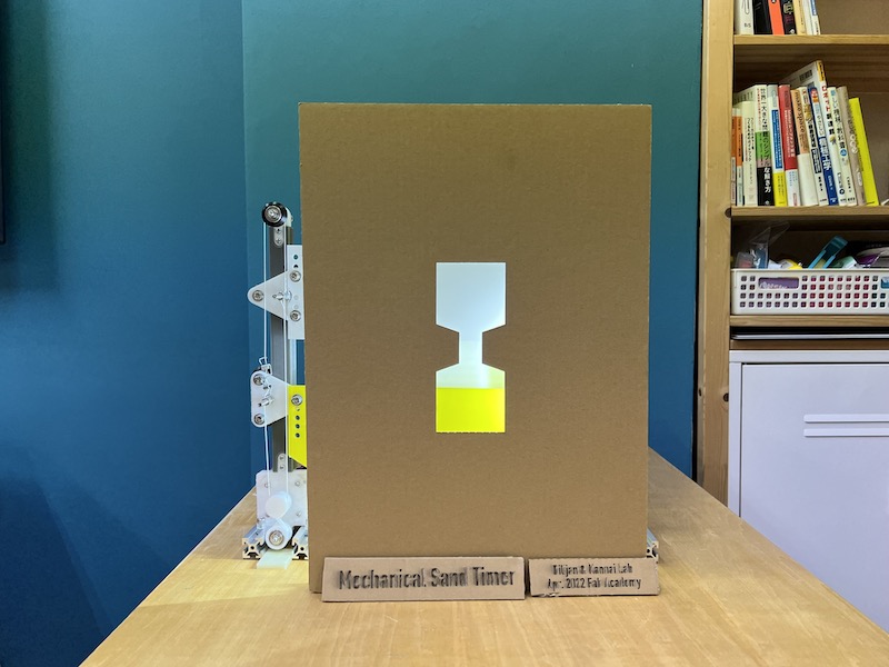
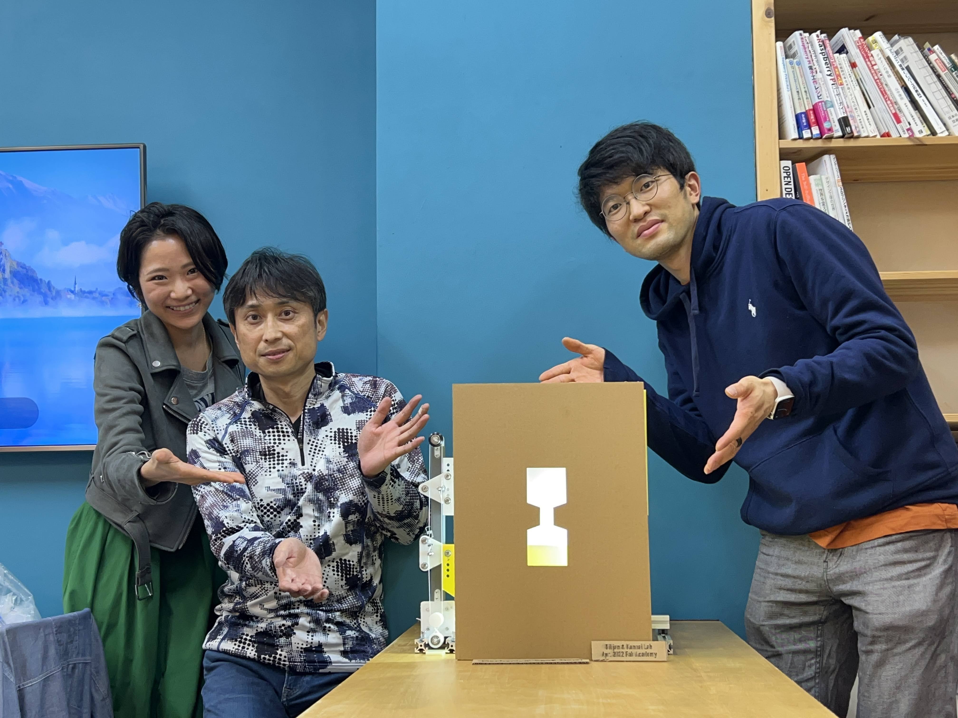
Mechanical Sand Timer (Kannai’s machine)
Final
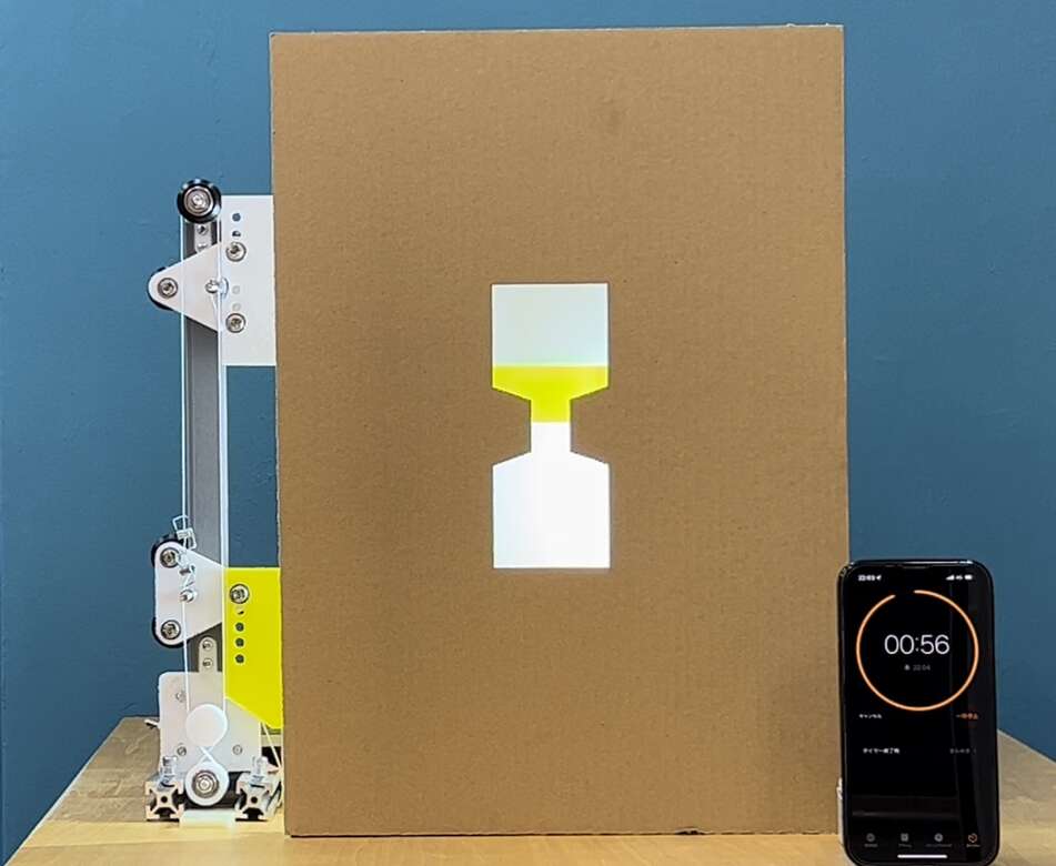
Kannai Machine
Design Process
It was decided that the 1 liniar axis moving parts to be output by 3D printing would be common parts with the lab. We decided to use that common component to build a timer that would measure one minute in each of the two labs.
Yukiya’s individual page is here. The following is content that was worked on independently by Fablab Kannai lab, so the same content can be found on my personal page.
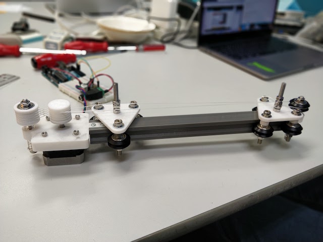
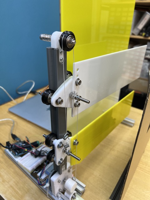
Building Process : Common parts
- Our common parts of 1-axis linear between in Dilijan lab and in Kannai lab
- We usedCommon axis parts by 3d printer
Extrusion Rail (Meshed)_250mm.stl
Carrier with ribs (Meshed).stl
Due to the size limitation of the 3D printer
Extrusion rails only 280mm → 250mm
Transform 3d data to g-code by Cura
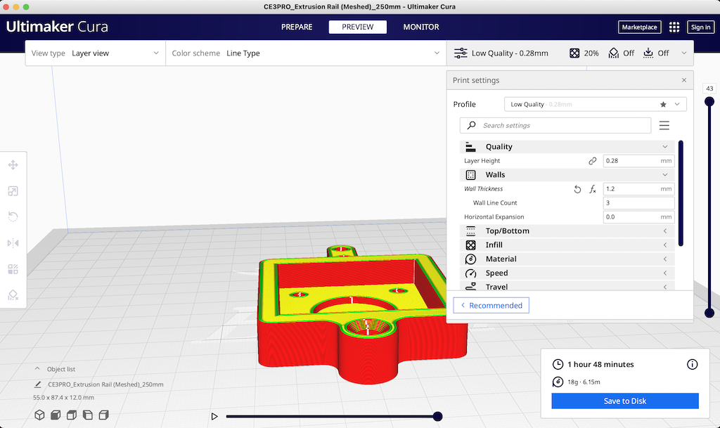
Low quality
Walls Wallthickness 1.2mm
Infill 20% cubic
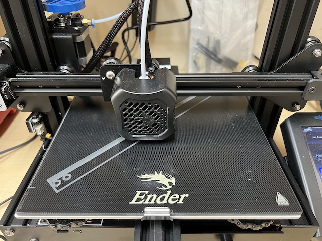
- 3D printed to make parts by Ender
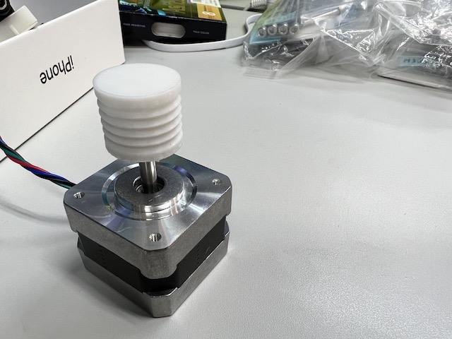
- stepper motor
We decided to use this stepper motor
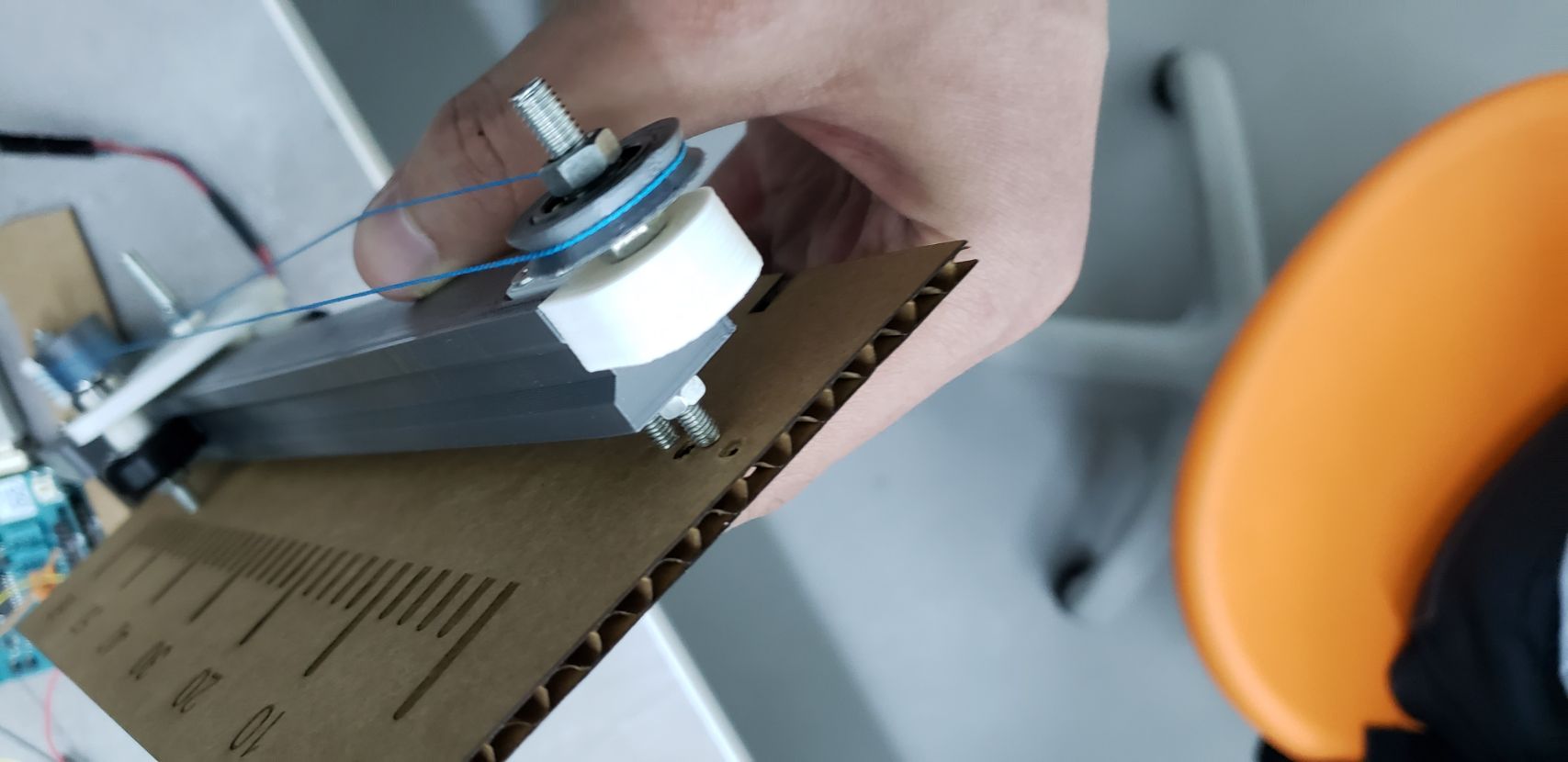
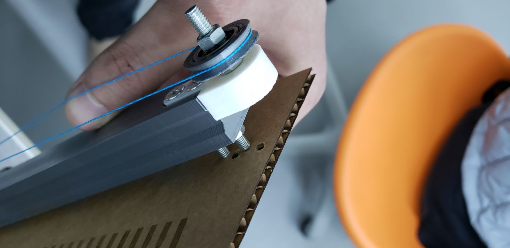
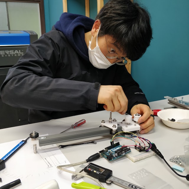
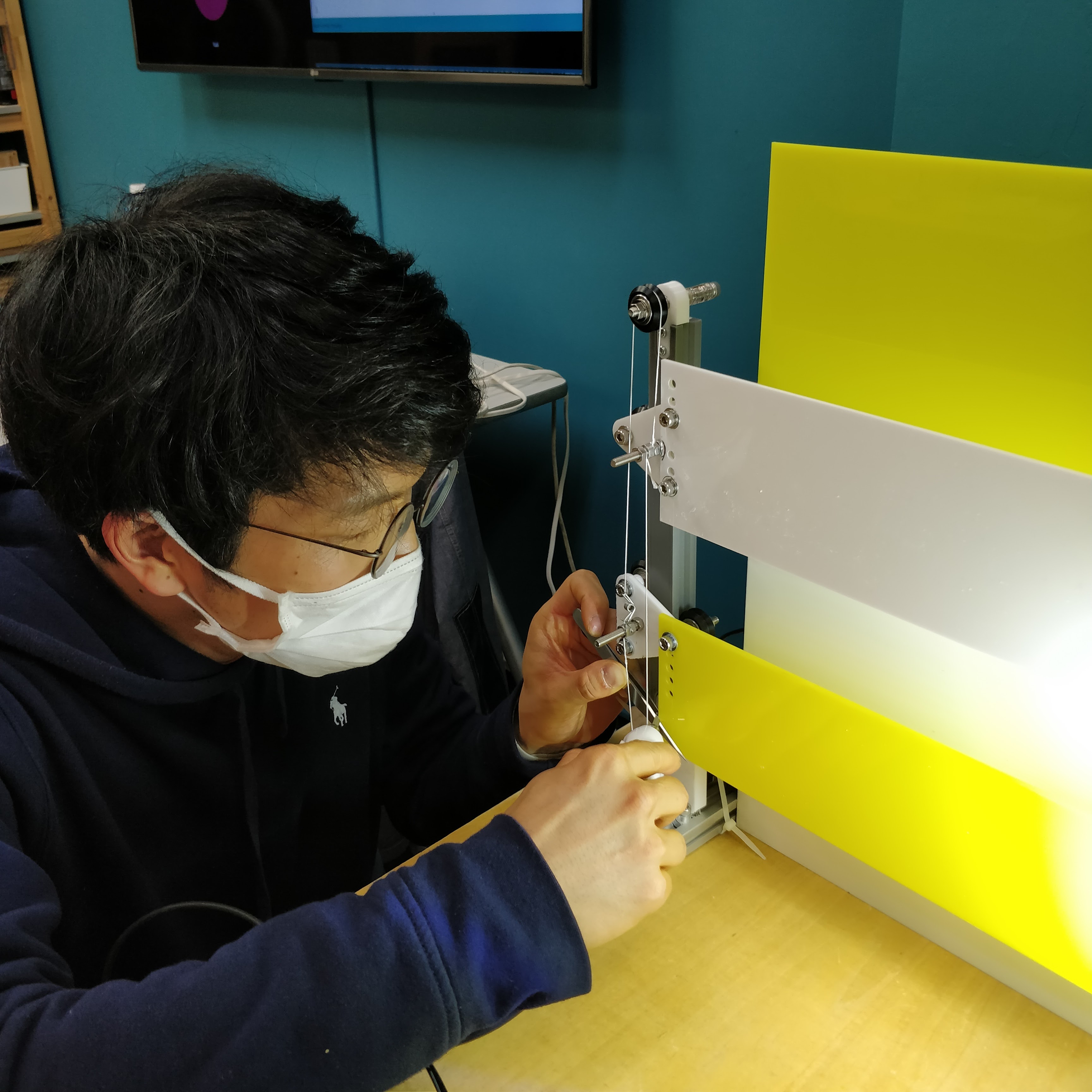
- Assembling
The kite string was wired to create the mechanism carefully.
-
finish to make the common parts with Dilijan Lab
-
Moving Test
Programming
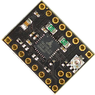
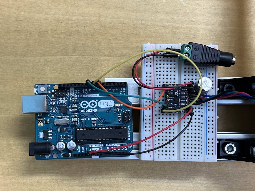
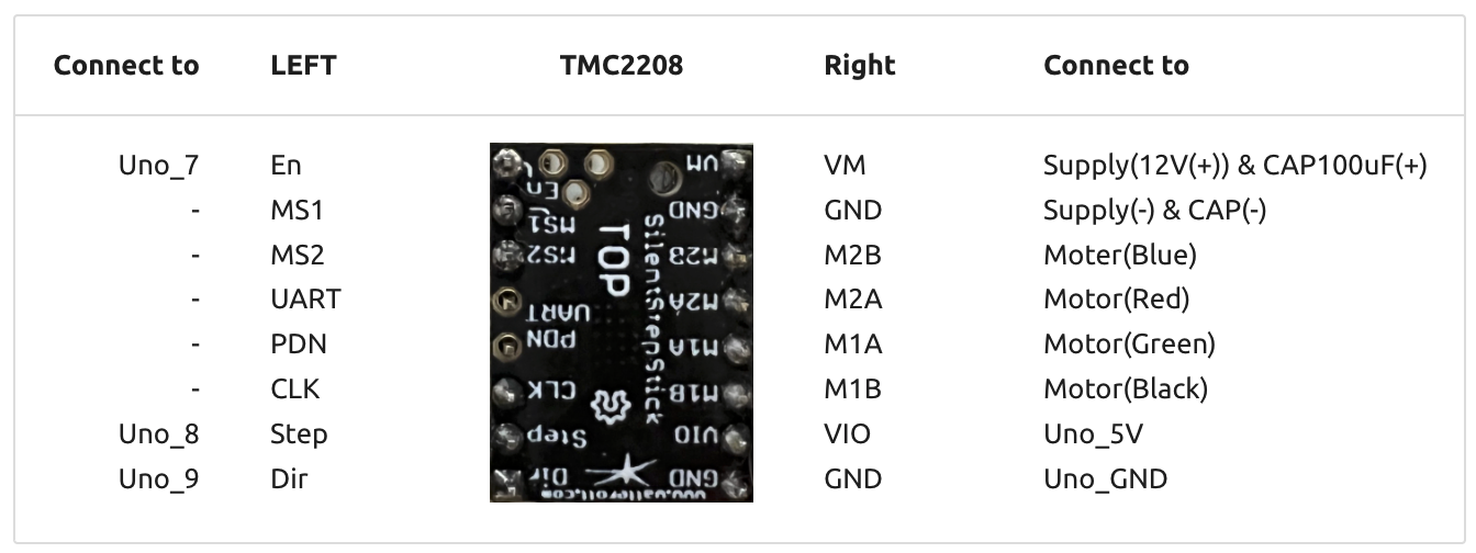
We decided to use Arduino Uno to control the move of the stepper motor. To use it, I connected Arduino Uno to Stepper Motor Driver TMC2208 refering to this Kannai Lab’s instruction Page.
Arduino uno
Stepper motor Driver TMC 2208
Connection
Test 1 : Move to 1 direction
Ref. GitHub project page
Download TMC220X.ino from here
/*
  SilentStepStick TMC2208/TMC2209 Example
  Rsense: 0.11 Ohm
  Other examples/libraries can be found here:
  https://github.com/teemuatlut/TMCStepper
  https://github.com/trinamic/TMC-API
  https://github.com/manoukianv/TMC2208Pilot
  Example source code free to use.
  Further information: https://learn.watterott.com/license/
*/

// Note: You also have to connect GND, 5V/VIO and VM.
//       A connection diagram can be found in the schematics.
#define EN_PIN    7 //enable (CFG6)
#define DIR_PIN   8 //direction
#define STEP_PIN  9 //step

void setup()
{
  //set pin modes
  pinMode(EN_PIN, OUTPUT);
  digitalWrite(EN_PIN, HIGH); //deactivate driver (LOW active)
  pinMode(DIR_PIN, OUTPUT);
  digitalWrite(DIR_PIN, LOW); //LOW to CCW
  //digitalWrite(DIR_PIN, HIGH); //HIGH to CW
  pinMode(STEP_PIN, OUTPUT);
  digitalWrite(STEP_PIN, LOW);

  digitalWrite(EN_PIN, LOW); //activate driver
}

void loop()
{
  //make steps
  digitalWrite(STEP_PIN, HIGH);
  delay(2);
  digitalWrite(STEP_PIN, LOW);
  delay(2);
}
It worked well.
Test 2 : Move back and forth
arrange code
/*
  SilentStepStick TMC2208/TMC2209 Example
  Rsense: 0.11 Ohm
  Other examples/libraries can be found here:
  https://github.com/teemuatlut/TMCStepper
  https://github.com/trinamic/TMC-API
  https://github.com/manoukianv/TMC2208Pilot
  Example source code free to use.
  Further information: https://learn.watterott.com/license/
*/

// Note: You also have to connect GND, 5V/VIO and VM.
//       A connection diagram can be found in the schematics.
#define EN_PIN    7 //enable (CFG6)
#define DIR_PIN   8 //direction
#define STEP_PIN  9 //step

void setup()
{
  //set pin modes
  pinMode(EN_PIN, OUTPUT);
  digitalWrite(EN_PIN, HIGH); //deactivate driver (LOW active)

  pinMode(DIR_PIN, OUTPUT);
  //digitalWrite(DIR_PIN, LOW); //LOW to CCW
  digitalWrite(DIR_PIN, HIGH); //HIGH to CW

  pinMode(STEP_PIN, OUTPUT);
  digitalWrite(STEP_PIN, LOW);

  digitalWrite(EN_PIN, LOW); //activate driver
}

void loop()
{

  for (int i = 0; i <= 255; i++){
  digitalWrite(DIR_PIN, LOW); //LOW to CCW
  //make steps
  digitalWrite(STEP_PIN, HIGH);
  delay(2);
  digitalWrite(STEP_PIN, LOW);
  delay(2);
  }

 for (int i = 0; i <= 255; i++){
  digitalWrite(DIR_PIN, HIGH); //HIGH to CW
  //make steps
  digitalWrite(STEP_PIN, HIGH);
  delay(2);
  digitalWrite(STEP_PIN, LOW);
  delay(2);
  }


}
It worked well.
Test 3 : Experiment about how to proceed
Since the time to turn the axis = the width of movement is controlled by changing the value of i, I set the value of i appropriately and observed how many centimeters the axis moved.
/*
  SilentStepStick TMC2208/TMC2209 Example
  Rsense: 0.11 Ohm
  Other examples/libraries can be found here:
  https://github.com/teemuatlut/TMCStepper
  https://github.com/trinamic/TMC-API
  https://github.com/manoukianv/TMC2208Pilot
  Example source code free to use.
  Further information: https://learn.watterott.com/license/
*/

// Note: You also have to connect GND, 5V/VIO and VM.
//       A connection diagram can be found in the schematics.
#define EN_PIN    7 //enable (CFG6)
#define DIR_PIN   8 //direction
#define STEP_PIN  9 //step

void setup()
{
  //set pin modes
  pinMode(EN_PIN, OUTPUT);
  digitalWrite(EN_PIN, HIGH); //deactivate driver (LOW active)

  pinMode(DIR_PIN, OUTPUT);
  //digitalWrite(DIR_PIN, LOW); //LOW to CCW
  digitalWrite(DIR_PIN, HIGH); //HIGH to CW

  pinMode(STEP_PIN, OUTPUT);
  digitalWrite(STEP_PIN, LOW);

  digitalWrite(EN_PIN, LOW); //activate driver
}

void loop()
{

  delay(5000);

  for (int i = 0; i <= 1600; i++){
  digitalWrite(DIR_PIN, LOW); //LOW to CCW
  //make steps
  digitalWrite(STEP_PIN, HIGH);
  delay(2);
  digitalWrite(STEP_PIN, LOW);
  delay(2);

  }

  delay(5000);

}
When i=500, it moved 20.8 mm.
i=500 *4 millsec =2 sec
Since moving 1.8 degrees is 1/8 microsteps, I calculated how many times it should be repeated
1.8 / 8 * i [steps] = 360
i = 1600 [steps] should be one revolution. The diameter of the gear is 20.6 mm, so the circumference is 3.14 * 20.6 mm * 1 round = 64.684 mm
When we actually measured the distance moved, the distance moved was exactly as it should be. So to count “1 sec”, I set “i=800”.
Final code : Programs that measure a minute
/*
  SilentStepStick TMC2208/TMC2209 Example
  Rsense: 0.11 Ohm
  Other examples/libraries can be found here:
  https://github.com/teemuatlut/TMCStepper
  https://github.com/trinamic/TMC-API
  https://github.com/manoukianv/TMC2208Pilot
  Example source code free to use.
  Further information: https://learn.watterott.com/license/
*/

// Note: You also have to connect GND, 5V/VIO and VM.
//       A connection diagram can be found in the schematics.
#define EN_PIN    7 //enable (CFG6)
#define DIR_PIN   8 //direction
#define STEP_PIN  9 //step

void setup()
{
  //set pin modes
  pinMode(EN_PIN, OUTPUT);
  digitalWrite(EN_PIN, HIGH); //deactivate driver (LOW active)

  pinMode(DIR_PIN, OUTPUT);
  digitalWrite(DIR_PIN, LOW); //LOW to CCW
  //digitalWrite(DIR_PIN, HIGH); //HIGH to CW

  pinMode(STEP_PIN, OUTPUT);
  digitalWrite(STEP_PIN, LOW);

  digitalWrite(EN_PIN, LOW); //activate driver
}

void loop()
{

 delay(3000);

  for (int i = 0; i <= 800; i++){  // center to xx cm in 30 sec

  digitalWrite(DIR_PIN, HIGH); //LOW to CCW
  //make steps
  digitalWrite(STEP_PIN, HIGH);
  delay(2);
  digitalWrite(STEP_PIN, LOW);
  delay(73);

  }

  delay(3000);

}
Original Parts in Kannai
What to create with a mechanism that measures one minute.
- Ideation
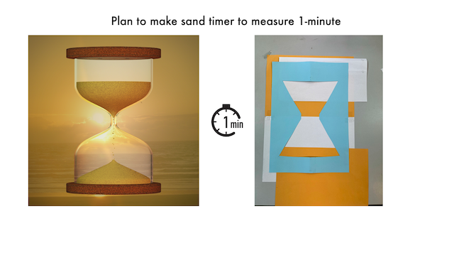
- Prototype of sand timer by 1-axis linear
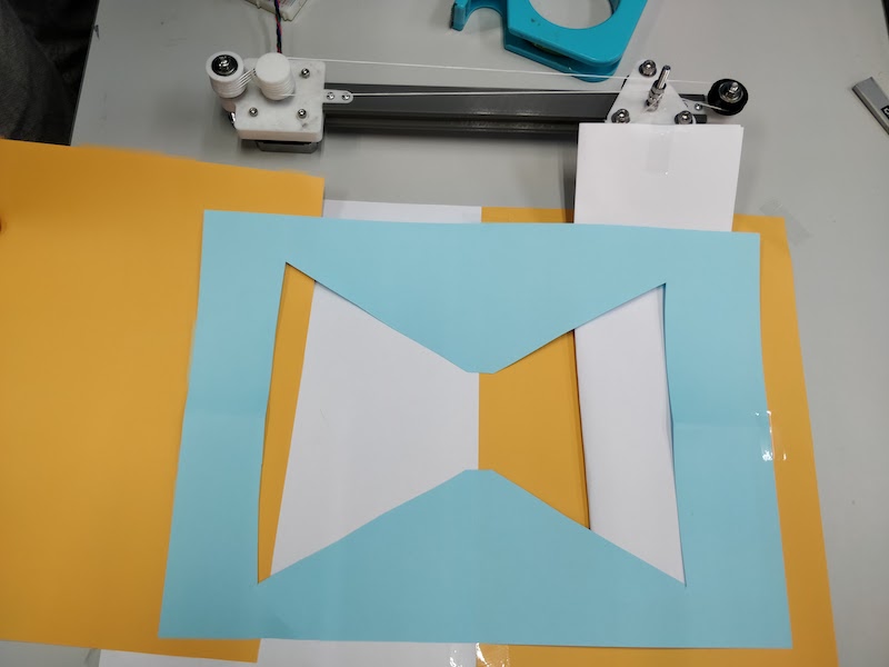
Prototype the use of two moving boards to see if an hourglass movement can be achieved.
- Finish to make the structure of vertical 1-axis linear
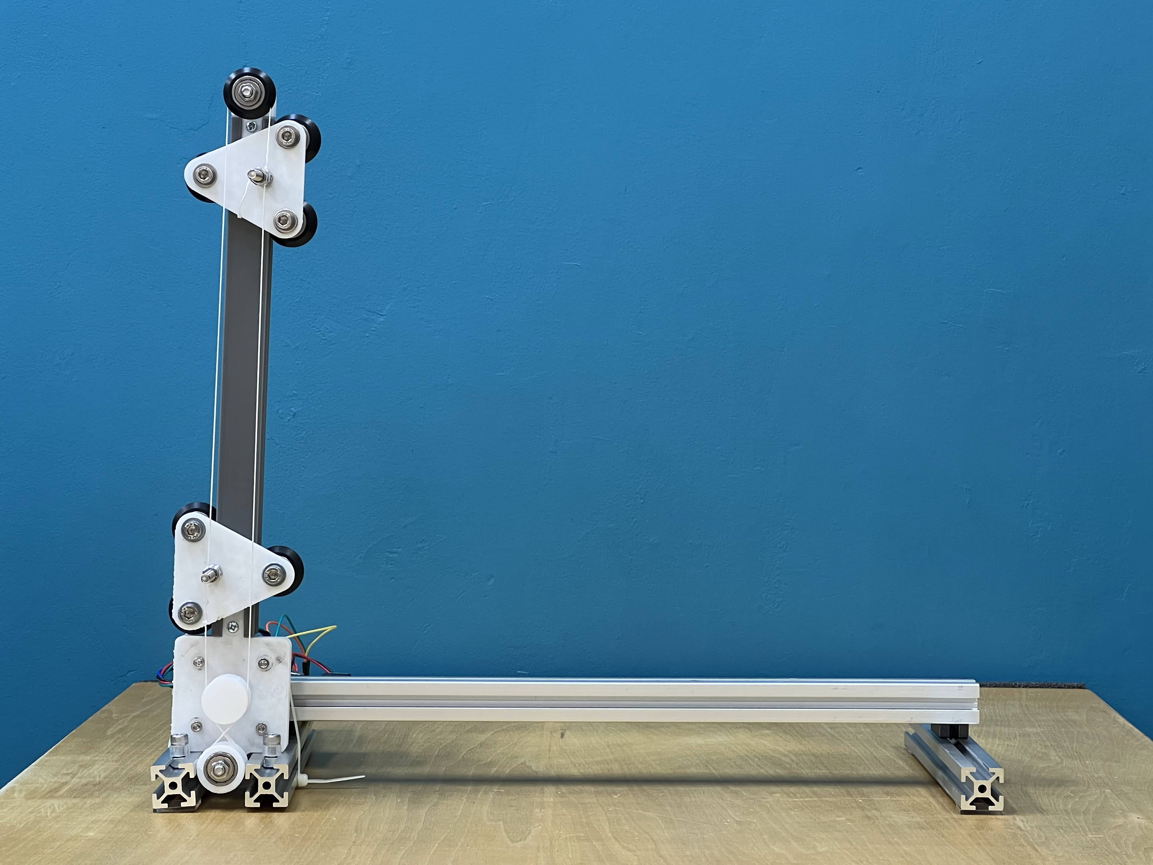
- embed programming
1 minute count programme
/*
  SilentStepStick TMC2208/TMC2209 Example
  Rsense: 0.11 Ohm
  Other examples/libraries can be found here:
  https://github.com/teemuatlut/TMCStepper
  https://github.com/trinamic/TMC-API
  https://github.com/manoukianv/TMC2208Pilot
  Example source code free to use.
  Further information: https://learn.watterott.com/license/
*/

// Note: You also have to connect GND, 5V/VIO and VM.
//       A connection diagram can be found in the schematics.
#define EN_PIN    7 //enable (CFG6)
#define DIR_PIN   8 //direction
#define STEP_PIN  9 //step

void setup()
{
  //set pin modes
  pinMode(EN_PIN, OUTPUT);
  digitalWrite(EN_PIN, HIGH); //deactivate driver (LOW active)

  pinMode(DIR_PIN, OUTPUT);
  digitalWrite(DIR_PIN, LOW); //LOW to CCW
  //digitalWrite(DIR_PIN, HIGH); //HIGH to CW

  pinMode(STEP_PIN, OUTPUT);
  digitalWrite(STEP_PIN, LOW);

  digitalWrite(EN_PIN, LOW); //activate driver
}

void loop()
{

 delay(3000);

  for (int i = 0; i <= 800; i++){  // center to xx cm in 30 sec

  digitalWrite(DIR_PIN, HIGH); //LOW to CCW
  //make steps
  digitalWrite(STEP_PIN, HIGH);
  delay(2);
  digitalWrite(STEP_PIN, LOW);
  delay(73);

  }

  delay(3000);

}
-
cut acrylic boards by laser cutter and set up them
mechanism of sand timer.
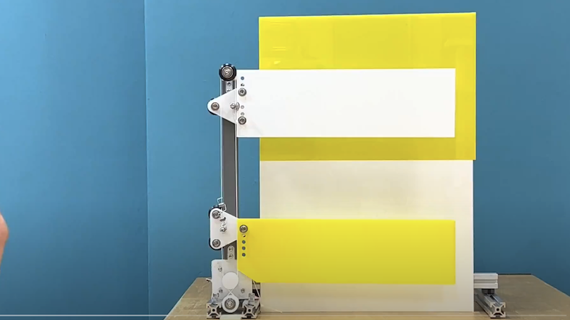
- mechanism test
-
cut cardboard by laser cutter and put the acliryc board on the cardboard
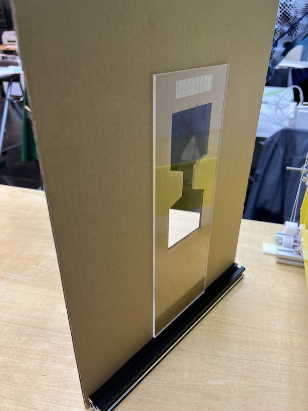
-
hero shot
BOM
| Parts | quantity | cost | source |
|---|---|---|---|
| Stepper motor | 1 | 1,100 yen | https://akizukidenshi.com/catalog/g/gP-14604/ |
| V Slot Model Pulley | 7 | 1482 yen | www.amazon.co.jp/dp/B078M191YS |
| Alminium frame | 3 | 469 yen x 3 | https://us.misumi-ec.com/vona2/detail/110302683830/ |
| Kite thread | - | - |
Files
3D print parts
Extrusion Rail (Meshed)_250mm.stl
Carrier with ribs (Meshed).stl
final code