6. Electronics design
nueval
- Startd
- April 13: break, midterm
- first half in nueval
- final project plan reviewed and site started
daylight savings time
Global
- March 13 US daylight savings time
- Mar 09 computer-controlled machining
- 23:00JST
- Mar 14 recitation: programming
- 22:00JST
- Mar 09 computer-controlled machining
Asian Review
- 21:00JST (no change)
Preparation for next week
Computer-Controlled Machining
group assignment
do your lab’s safety training
test runout, alignment, speeds, feeds, materials, and toolpaths for your machineindividual assignment
make (design+mill+assemble) something big (~meter-scale)
extra credit: don’t use fasteners or glue
extra credit: include curved surfaces
Hamamatsu
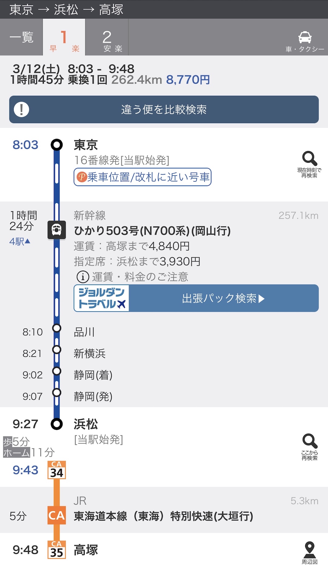
- message me when on board
- Rendezvous point: Tokaido line platform
- Ms.Takemura will wait us at Takatsuka Sta. of North entrance
Preparation
- Read Assessment
How big is big?
Answer: Life size, big enough to show you understand many of the possibilities of CNC machining - drill, pocket, dogbones, nesting, etc.
Neil: “at least one dimension should be larger than 1m”!?
-
material
- 910x1820mm x2 (Group x1, Individual x1)
- shop stock 2017
-
Read Tips
-
Finish Parametric Design in Fusion360
- Material Thicness
- is not exact number in written
- may sold out
- may change your mind in store
- Dogbone
- Material Thicness
- Online Local session
- Thursday or Friday
- You should have
- Gloves (you and some from lab and 5F)
- Eye protection (from Lab)
- Caliper (from my home)
- Sander (from 5F)
- for packaging to home
- Lunch
Mystery of Bootloader
Arduino Bootloader
What’s a Bootloader?
Microcontrollers are usually programmed through a programmer unless you have a piece of firmware in your microcontroller that allows installing new firmware without the need of an external programmer.
This is called a bootloader.
From Instructor and Staff group
both SAMD and AVR can work without bootloader. For SAMDs, the role of the bootloader is to accept firmware uploads through serial over USB, without any additional hardware. Hence you only need a programmer connected to it the first time you flash the bootloader. But if you wish, you can also keep using the programmer and edbg every time you upload, it’s simply a lot less convenient. Arduino stores its binary in a hidden folder before uploading, so you could simply find it and upload it with edbg instead.
For the AVR, uploading through UPDI requires some USB-serial programmer connected to it, because the AVR itself doesn’t support USB. Optiboot is an optional bootloader that can take uploads through a regular serial port of the AVR instead of the UPDI port. But you will still need a USB-serial adapter next to your AVR. This is similar to how Arduinos (ATmega type) work too, they have a serial USB adapter onto the board, connected to one of the serial ports of the ATmega, and take firmware uploads through there.
| FamilyMCU | Interface | upload programwithout bootloader | upload programafter burned bootloader |
|---|---|---|---|
| Original AVRATmega328P | ISP | Via programmer(fab ISP) | serial over USB with external Serial-USB board |
| AVR-13216 | UPDI | Via programmer(USB-Serial board & Serial-UPDI board) | serial over USB with external Serial-USB board |
| ARMSAMD11C | SWD/JTAG | Via programmer(freeDAP board) | serial over USB with internal Serial-USB function |
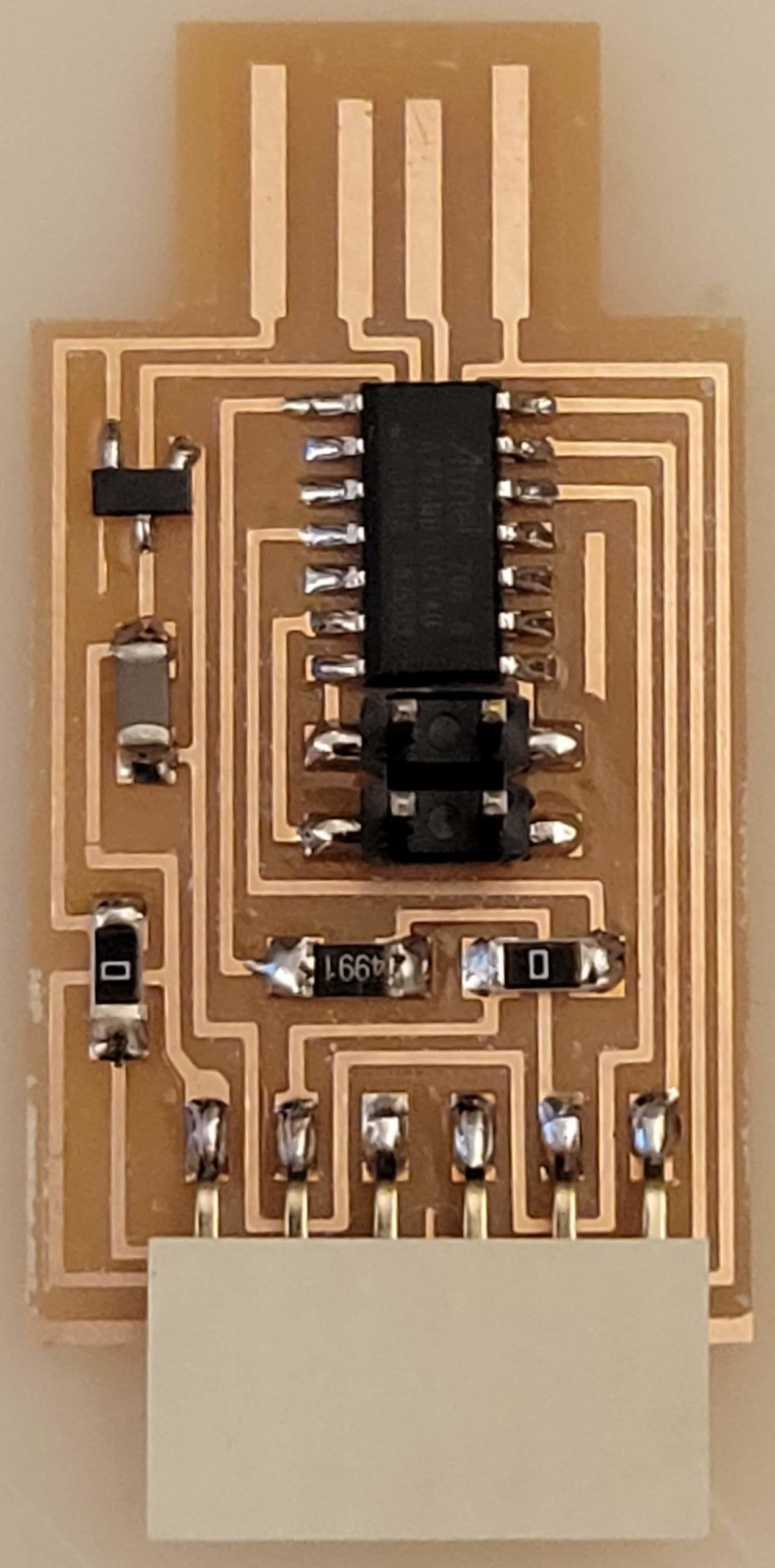
Group Assignment
use the test equipment in your lab to observe the operation
of a microcontroller circuit board
test equipment
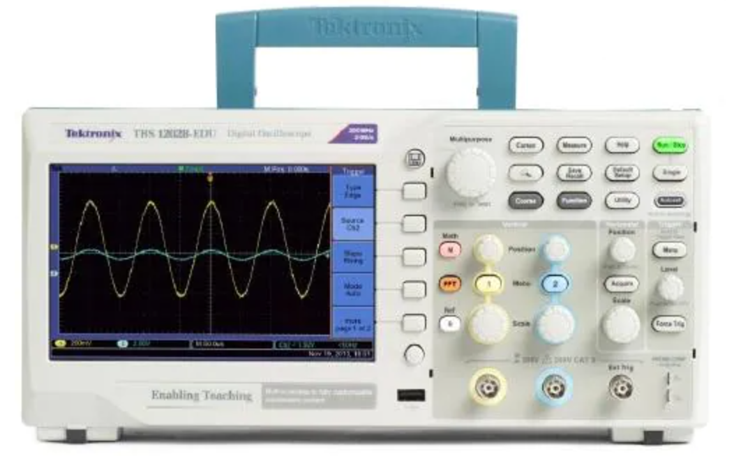
Oscilloscope
- TektronixTBS1052B
Note
Screenshot(Setup the button)
Insert USB memory
Utility > Options > Printer Setup
Ink Saver On > Off
Save/Recall(on Front panel button)
Action > Save Image > Select Save option
Note
Screenshot
Save/Recall (on Front panel button) > Action
Save All > Print button > Saves Image to File
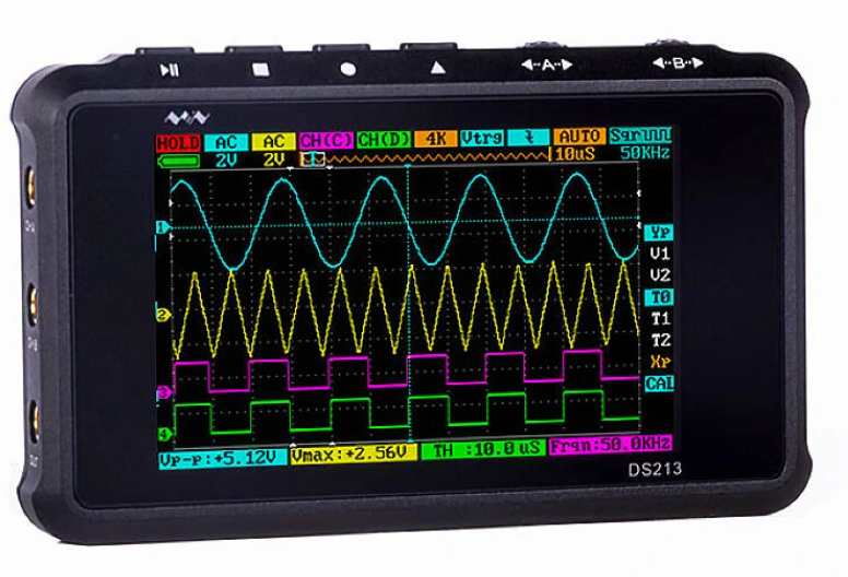
- Mini DSO DS213
Multimeter
ToDo
Multimeter
- Measure Voltage between IC2 IN and GND
- USB 5V
- Measure Voltage between IC2 OUT and GND
- IC2: 3.3 Regulator
- IC REG LINEAR 3.3V 100MA SOT23-3
- SAMD11C
- Check Connection
- soldered (Connected)
- short (should not be connected, but connected)
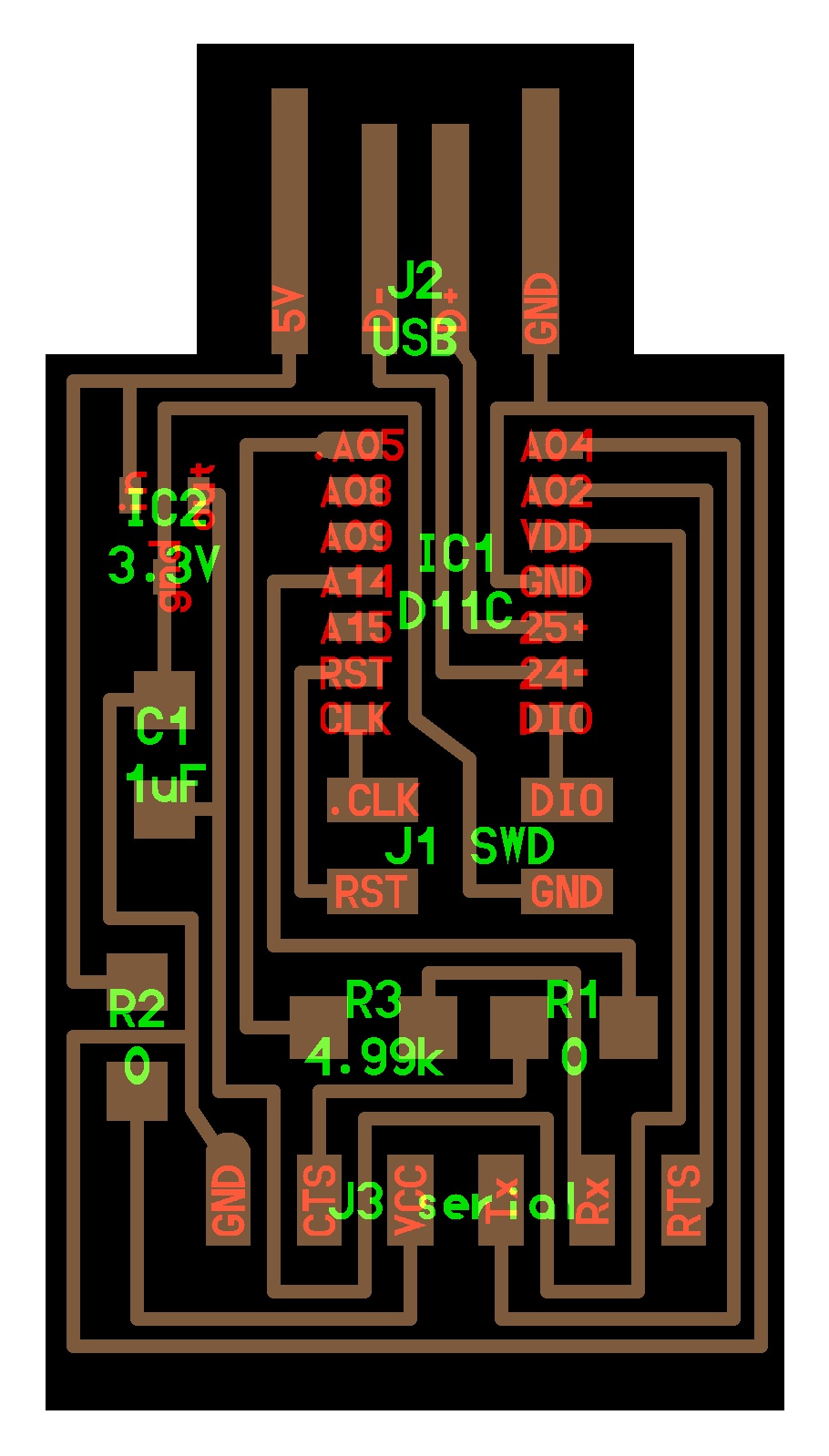
Oscilloscope
- Read Oscilloscope
- upload echo program to 3216 breakout board
-
Probe TX, RX line (and GND)
- TX(Transmitter): USB-Serial-D11C(3.3V) -> t3216(5V)
- RX(Receiver): t3126(5V) ->(R3_4.99k)-> USB-Serial-D11C(3.3V)
- Open Serial Monitor in Arduino IDE and send Character (1-9. A-Z, a-z… )
- Data bits Will be send from LSB (least significant bit)
- ASCII
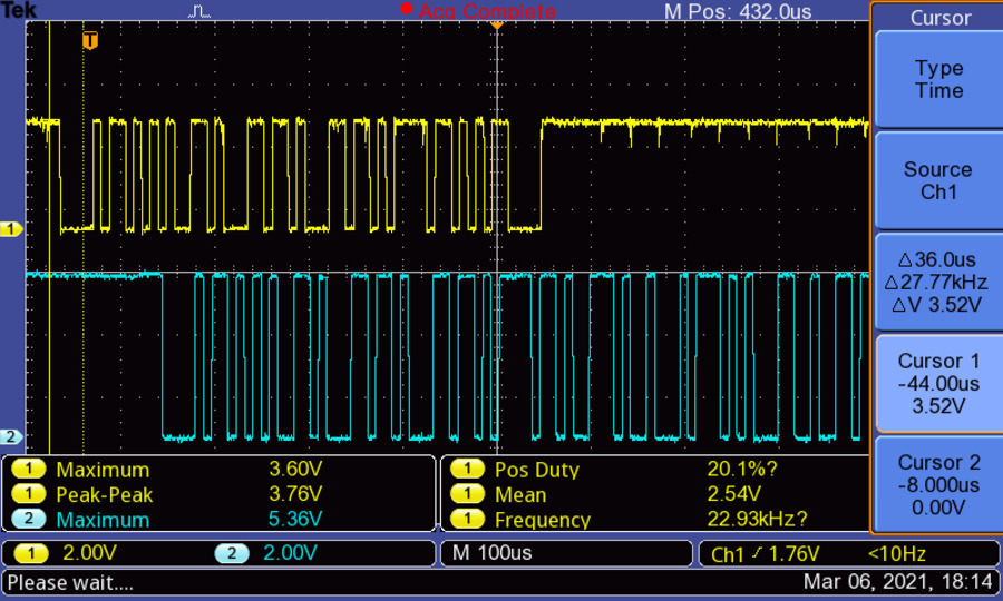
-
Probe RX line
- between before 4.99k register (t3216 side) and GND
- between after 4.99k register (D11C side) and GND
-
Probe RX_t3216_side line and RX_D11C_side line
- may see voltage drop 1.7V(= 5-3.3V)
Note
Ref. Quentin_2020
The UART connector is directly wired to the RX and TX of the serial 0 on the D11C. On the RX pin, the 1.2 kΩ resistor offers some protection in case the other device is talking in 5V serial. The internal protection of the D11C saturates inputs to VDD+0.6V, but can only accept a small injection current. According to the datasheet, we should be safe in this case. Let’s compute the current when RX is at 5V:

which is below the reported limit. When enabling the UPDI mode with the jumper, the RX and TX pins are simple shorted together, along with a 4.7 kΩresistor. This resistor limits the current to the TX pin, which is low impedance as it is configured as an output on the D11C. The value of this resistor is not critical, you can also use 5 kΩ.
Note
Level Shift 5V to 3.3V

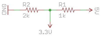
Ref. How to Level Shift 5V to 3.3V
Echo.ino
void setup() {
  Serial.begin(115200);
}

void loop() {
  if(Serial.available() > 0){
    Serial.write(Serial.read());
  }
}
Result of last year
Individual Assignment
redraw an echo hello-world board,
add (at least) a button and LED (with current-limiting resistor)
check the design rules, make it, and test that it can communicate
extra credit: simulate its operation
components
Button / Tactile switch

ちなみに、タクトスイッチには4つ足がついていますが、足が向かい合っているところは元からつながっています。 こんな単純な仕組みなのに、たまに「どっちだっけ?」って思ってしまうのが人間というものです。 なので私は、確実に導電していない斜め向かいに線を繋げるようにしています。頭いいな〜。
- normally open
- open may mean parts missing
- normally close
LED
-
polarized
- anode(+)
- cathode(-): cathode line
- cathode(en)
- Kathode(de)
-
- Voltage - Forward (Typ) VF = 2.1V
- Current - Test = 10mA
Attention
Ohm’s law
V=IR
R=V/I
Resistor
- size
- 1206
- 0.12” x 0.06”
- 3216(Metric)
- 3.2mm x 1.6mm
- 1206
- value
- 4991 = 499 x 10^1 = 4990 = 5k[ohm]
- 4990 = 499 x 10^0 = 499 = 500[ohm]
- color code
- APP
- current-limiting resistor
- Ref. LED Basic_JP
- R = (E -VF)/IF = ( 5[V]-2.1[V] )/10m[A] = 2.9[V]/10m[A] = 290[Ohm]
- E: electromotive force
- Pull up / Pull down resistor
- Ref. here_JP
pinMode(2, INPUT);

pinMode(3, INPUT_PULLUP);
IC
- AVR-1
- 412
- 4: 4KB Flash memory
- 1: AVR-1
- 2: 8 pins
- 1614
- 4: 14 pins
- 3216
- 6: 20 pins
- 412
- Ref. 3216 datasheet Figure 1-1.
- pinout
Todo
Eagle
- download site
- Library
-
tips
-
Design roule
- Eagle: DRC
- 16mil = 16 milli-inch = 0.4064 mm
- Eagle: DRC
Test
- echo
- class page
- Flash sound
- buzzer
- Step Response / CapacitiveSensor