Registers
Attention
resistor[ruh_zi_str] : electrical component that implements electrical resistance
register[reh_juh_str] : a memory location within the actual processor that work at very fast speeds
n-ary numbers
- 1 byte = 8 bits = 2^8 = 256 = [7:0]
-
1 B = 8 b
JP EN usable 15 255 255 2進数 Binary 0,1 0b1111 0b11111111 B11111111 10進数 Decimal 0,1,2,3,4,5,6,7,8,9 0d15 0d255 255 16進数 Hexadecimal 0,1,2,3,4,5,6,7,8,9,A,B,C,D,E,F 0xf 0xff $f
Note
1kB = 1 [kilo] byte = 1000 B
1KB = 1 [ke̞ː] byte = 1024 B = 2^10 B = 1KiB = 1 [kibi] byte
1 bps = 1 [bits per second]
pinout
Datasheet
5. I/O Multiplexing and Considerations
5.1 Multiplexed Signals

Pin names are of type Pxn, with x being the PORT instance (A, B) and n the pin number. T``
16 . PORT - I/O Pin Configuration
16.1 Features
General Purpose Input and Output Pins with Individual Configuration:
– Pull-up
16.2 Overview
The I/O pins of the device are controlled by instances of the PORT peripheral registers. Each PORT instance has up to eight I/O pins. The PORTs are named PORTA, PORTB, PORTC, etc.
Each PORT pin has a corresponding bit in the Data Direction (PORTx.DIR) and Data Output Value (PORTx.OUT) registers to enable that pin as an output and to define the output state. For example, pin PA3 is controlled by DIR[3] and OUT[3] of the PORTA instance.
16.4 Register Summary - PORTx
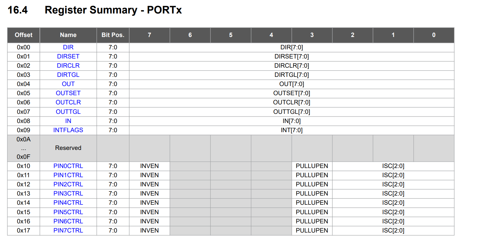
16.5.1 Data Direction
Name: DIR
This bit field controls the output driver for each PORTx pin.
| Value | Description |
|---|---|
| 0 | Pxn is configured as an input-only pin, and the output driver is disabled |
| 1 | Pxn is configured as an output pin, and the output driver is enabled |
16.5.5 Output Value
Name: OUT
This bit field controls the output driver level for each PORTx pin.
| Value | Description |
|---|---|
| 0 | The pin n (Pxn) output is driven low |
| 1 | The Pxn output is driven high |
16.5.9 Input Value
Name: IN
This bit field shows the state of the PORTx pins when the digital input buffer is enabled
| Value | Description |
|---|---|
| 0 | The voltage level on Pxn is low |
| 1 | The voltage level on Pxn is high |
Program
Arduio Sketch
void setup() {
  pinMode(8, OUTPUT);
}
void loop() {
  digitalWrite(8,HIGH);
  delay(500);
  digitalWrite(8,LOW);
  delay(500);
}
void setup() {
  PORTA.DIR |= 0b00000001;//ポートAの0番ピン(Arduinoの11番ピン)をOUTPUT
}
void loop() {
  PORTA.OUT |= 0b00000001;//ポートAの0番ピン(Arduinoの11番ピン)をHIGH
  delay(500);
  PORTA.OUT &= ~0b00000001;//ポートAの0番ピン(Arduinoの11番ピン)をLOW
  delay(500);
}
AVR
void setup() {
  DDRB |= 0b00000001;//ポートBの0番ピン(Arduinoのn番ピン)をOUTPUT
}
void loop() {
  PORTB |= 0b00000001;//ポートBの0番ピン(Arduinoのn番ピン)をHIGH
  delay(500);
  PORTB &= ~0b00000001;//ポートBの0番ピン(Arduinoのn番ピン)をLOW
  delay(500);
}
Ref. Arduinoで入出力を高速化する方法
Hint
代入
a = 0; //初期値 代入
b = a + 1; //代入
a = a + 1; //加算代入
a += a; //加算代入
OR
PORTB.DIR = 0b00000001; //初期値
PORTB.DIR = PORTB.DIR | 0b00010000 //OR
PORTB.DIR |= 0b00010000 //OR
<!-
DDRB = 0b000000; //初期値
DDRB = DDRB | 0b00000001; //OR
DDRB |= 0b00000001; //OR
->
Bitwise Operators (bit演算子)
| 機能 | 演算子 | 使用例 |
|---|---|---|
| OR | | |
指定bitのセット |
| AND | & | 指定bitの取り出し, NOTと併用した指定bitのクリア |
| XOR | ^ | bit反転 |
| NOT | ~ | bit反転, bitクリア |
| ビットシフト(右) | >> | ビットシフト |
| ビットシフト(左) | << | ビットシフト |
Note
operand: 被演算子
OR
0  0  1  1    operand1
0  1  0  1    operand2
----------
0  1  1  1    (operand1 | operand2) - returned result
NOT
0  1    operand1
-----
1  0   ~operand1
AND
0  0  1  1    operand1
0  1  0  1    operand2
----------
0  0  0  1    (operand1 & operand2) - returned result
See example below
ref. Arduino Language Reference
Example
void setup() {
  PORTA.DIR |= 0b00010001; //Set PA4 and PA0 to OUTPUT
}

void loop() {
  PORTA.OUT |= 0b00000001;  //Set PA0 to HIGH...(1)
  delay(500);
  PORTA.OUT |= 0b00010000;  //Set PA4 to HIGH...(2)
  delay(500);
  PORTA.OUT &= ~0b00000001; //Set PA0 to LOW ( Remaining PA4 setting )....(3)
}
What to work in (1)(2)(3)
(1) OR
0000 0000   operand1_1
0000 0001   operand1_2
---------
0000 0001   (operand1_1 | operand1_2) - returned result1

(2) OR
0000 0001   operand2_1 (returned result1)
0001 0000   operand2_2
---------
0001 0001   (operand2_1 | operand2_2) - returned result2

(3)
(3-1) NOT
0000 0001   operand3_1
---------
1111 1110   ~operand3_1

(3-2) AND
0001 0001   operand3_2 (returned result2)
1111 1110   ~operand3_1
---------
0001 0000   (operand3_2 & ~operand3_1) - returned result3