Output Devices 
Assignment
Individual assignment
- Add an output device to a microcontroller board you've designed,
- and program it to do something
Group assignment
- Measure the power consumption of an output device
See more info and recording of the lecture here.
Neil's board
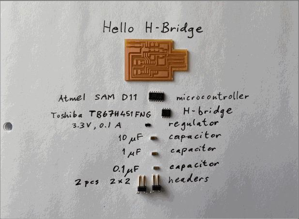
I first made Neil Gershenfeld's Hello H-Bridge D11C board without modifications. I simply downloaded the traces and interior PNG files and used them to generate G-code to mill the board. After milling, I removed the extra copper around the USB connector, to avoid a short-circuit.
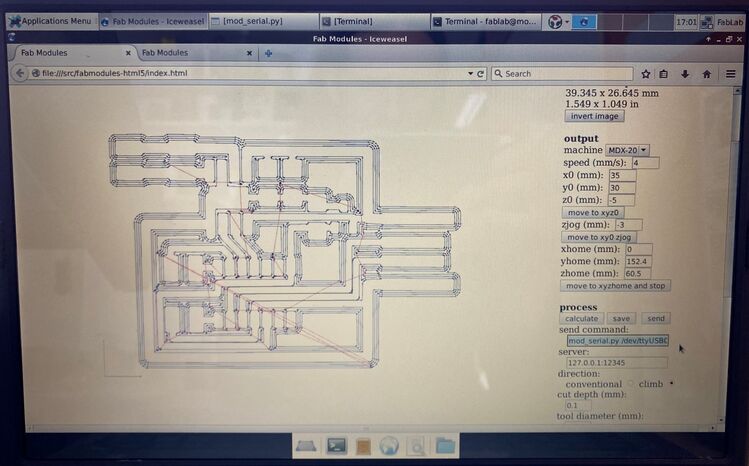 Neil's board in Fab Modules.
 I like soldering. Maybe you can tell.
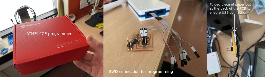
I like the fact that the SAMD11 is a capable ARM microcontroller that still comes in a package that is easy to solder. After soldering, I plugged the USB connector on the board into my computer and hooked the SWD pins up to the Atmel-ICE programmer. I followed this tutorial from Fab Lab Kannai to try to upload a bootloader to the chip.
 Trying to program the ATSAMD11C with the official ATMEL-ICE programmer.
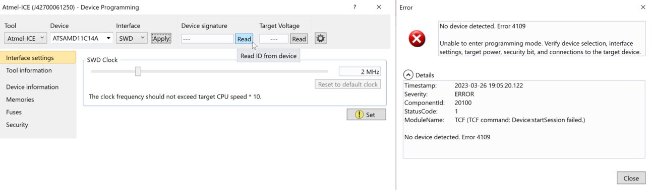 The microcontroller was not detected.
The Microchip Studio software couldn't find a connected device. I tried again, and got a low voltage warning. It said that the operating voltage was 1.5 volts but needed to be 1.6 to 3.8 volts. Well, that's an improvement! Now I have a useful error message that I may be able to do something about. Later.
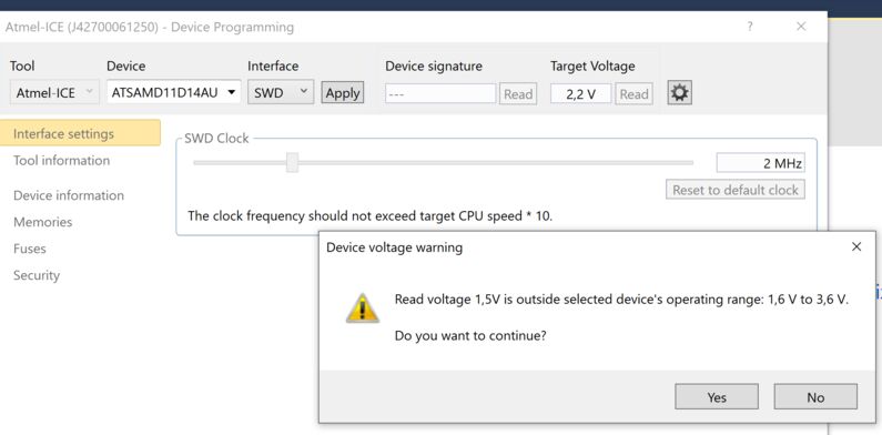 At least the computer is detecting something.
2024 update
I used Yuichi's guide to using the Xiao SAMD21 as a programmer. Yuichi's documentation is usually really good, and this guide is no exception.

I set the Xiao SAMD21 to bootloader mode and dragged the CMSIS-DAP firmware into the folder that opened. That was enough to make the Xiao a programmer. Then I connected the pins as shown in the guide and used the Generic D11C14A board definition in the Fab SAM core for Arduino. Remember to select TWO_UART... Tools->Serial Config and choose CMSIS-DAP as the programmer. Then burn the bootloader.
Then you can disconnect the Xiao and the SAMD11 board. When you reconnect the SAMD11 board it gets recognized and you can now program it over USB! So convenient with such a small and cheap chip!
Only a year later, it works!
I couldn't get the SAMD11-based programmer to work until I tried connecting the target board to a USB power brick instead of the computer. If the target board has already been programmed, then it shows up as a COM port and that can confuse the computer.
 The SAMD11 programmer from Fab Fest Bali is now working.
I also bought thirty Raspberry Pi Pico W boards for my students to use. I tried using one of them as a programmer and it also works, when I connect the target board to a USB power brick. Now I have no shortage of programmers for the SAMD chips.
 Raspberry Pi Pico W being used as a programmer.
Here is a summary of the Fab Academy programmers.
Stepper control board
Fusion 360 PCB export woes
For my own design, I decided to go an easier route. I used the Xiao RP2040 module, which I know how to program. After the incredible fireworks show in the Monday recitation, where the Fab Lab machine builders showed their projects, I looked into the Urumbu boards and Modular Things. Urumbu is based on work at a Fab event in Kerala, where it was discovered that you can connect several stepper control boards directly to a computer and send them synced commands via USB and have them act as a single machine. Modular Things grew out of that project, and they include a convenient web editor to program the boards with a few lines of JavaScript.
I looked at the Urumbu boards and found that they used the DRV8428 stepper controllers. We only have two of them, and they are currently unavailable at Digikey. However, the latest Modular Things boards use a Xiao RP2040 for control, which I'm comfortable with, and the stepper board uses two A4950 motor controllers, which we have at our Lab. Alright! These boards are designed in Fusion 360 and I want to make some modifications to it. I opened the stepper board in Fusion 360 but I couldn't make heads or tails of the interface of the electronics environment.
So I started going through a friendly five video tutorial series on Fusion 360 PCB design and milling. The first video covers making a new design, getting the libraries you need and opening the PCB layout. The video was made only a year ago but the interface has already changed since then. But I was able to follow it. In the second video you make your own library component from scratch. I needed to change the default grid units from mils to millimeters first. That is a global setting, so I should now see millimeters everywhere in the electronics design environment. In the third video, you make a more complicated component from the manufacturer's 3D CAD file and technical drawing. When I made a new component, I had to set the grid units to mm again. Annoying.
I followed step 5 on this Fab Academy site to export the circuit as a PNG. That worked well for the traces, but no matter what I tried, I couldn't export the outline of the board. It's always visible in the viewport, even when I turn off all the layers. So instead, I tried opening the 3D PCB and exporting the PCB sketch as a DXF and then turning that into a black and white SVG in Inkscape. That works, except I need to draw a frame around it, so that the milling bit has space to traverse the whole outline. But then, how do I make the frame for the traces? I tried to export them as a DXF, but that didn't work. For that, I would need to create another sketch inside the 3D PCB environment and project the traces into it, but that environment only allows you to make one sketch.
Then I tried to make an engineering drawing. Only the board outline and the pads appeared but not the traces. And not the frame around the board, because it only exists in a sketch. Then I changed the settings for the model view from Visible Lines to Visible with Hidden Edges, and the traces appeared! But they had broken lines. So I right-clicked the Document Settings at the top of the model tree on the left and looked at the View settings. The hidden lines were drawn with HIDDEN2. I changed that to Continuous, and now I had nice and continuous traces. I exported the drawing as a PDF and opened it in Inkscape. I deleted the CAD drawing frame, which I don't need to make production files. Now I just needed to do some editing to combine the traces with the pads and make one file with only the traces and another one with only the holes and the board outline. I made all the lines red and 0.02 mm wide, just because that's what we usually do before laser cutting and vinyl cutting. I'm used to looking at things like that.
I tried turning on Fill, but that didn't come out well. So I had to do some editing. I selected Object -> Ungroup twice to separate all the lines. I thought that I was getting close to production. But a lot of the lines weren't connected. Sigh. I can't use this.
Next I tried exporting the CAD drawing as a DXF and opened it in Inkscape, in the hope that it would be more precise. It is more precise, but the lines are still all seperate. The pads and traces aren't objects that I can combine. I tried turning Fill on, but had no better luck than with the PDF.
To make the background, I made a rectangle with black fill and no stroke, and had it snap to the corners of the broken sketch outline.
 Nicely milled stepper control board.
When I was looking through the Arduino code for the stepper H-bridge RP2040, I found the pin that sends a reference voltage to the Toshiba driver. It was in the stepperDriver.cpp file. Connected to the pin was a somewhat cryptic slice_num variable, but from the RP2040 datasheet I remembered that the PWM generators are called slices. From the following lines of code, it seemed that the PWM duty cycle was 15/128, or 12%:
cpp
  // PWM duty cycle over 128
  pwm_set_chan_level(slice_num_a, channel_a, 15);
  pwm_set_chan_level(slice_num_b, channel_b, 15);
If I assume that the maximum output voltage of the RP2040 is 3.3V, then 12% of that is 0,396V. I can try to implement this with the Arduino library function analogWrite(pin, value), where value takes a number from 0 (always off) to 255 (always on). 12% of 255 is 31.
The DC motor hummed, but didn't move. So I tried 50/255. Then it moved a tiny bit. Next, I tried 80/255. The motor spins! And I don't seem to be overloading the USB port. But the motor is very weak. Let's try 100. Now 120. Now 150. Now 180. Now 200. Now 220. I won't dare to go above that for now.
Two DC motors, VREF 80. Works! Let's try 120. I tried 150, 180 and finally 220.
I also tried PWM on both motors at the same time. That worked well. Now I'm gearing up for a BLDC motor. But that requires a boost converter to get the voltage from 5 to 12 V.
Final project spiral 1
Yuichi's board
Then I tried Yuichi Tamiya's Modular Things stepper board.
 Yuichi Tamiya's Modular Things stepper board from the 2023 instructor bootcamp in Amsterdam.
This is the last board that Andri made in Machine week with the help of our instructors. It worked, so immediately after I got back to Ísafjörður I made one of my own:
OMG, it's so smooth and quiet!
 Þórarinn found me all excited when he came to work. Fig rolls and the trusty Tandy 102 by my side, and a candle lit on my desk to keep my father with me as I work. He would have loved this.
Design file
Download Stepper H-bridge RP2040 Modular Thing Arduino code
Spiral 1 3D design
I was so excited to see a motor moving that I immediately started to design 3D printed parts for spiral 1 of my robot arm.
 I bought two sizes of brushless motors, thinking that I would use a bigger motor in the base. I based the shape of the board on that.
A few days after I designed the shape, I decided to change the orientation of the arm from vertical (regular robot arm) to horizontal (SCARA arm). Then there's no strain on the motors when the arm is stationary and I don't need to use the bigger and more expensive brushless motor. I also decided to keep the stepper in the base, not because I wanted to use a stepper but simply because I had a working stepper. Spiral development!
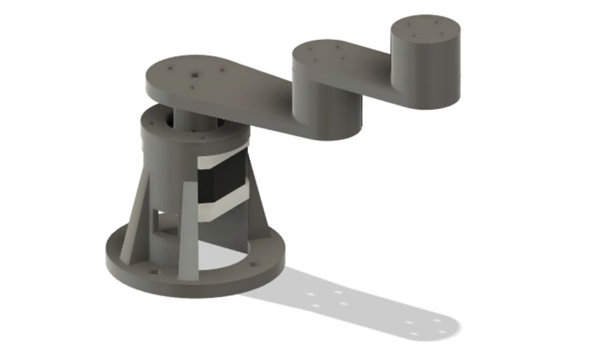 This Fusion 360 model is named stepper_festing, which means stepper_bracket. I only meant to design a fixture for the stepper, but it quickly turned into a whole robot arm.
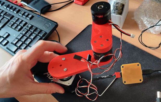 Assembling spiral 1 of my robot arm.
Robot base
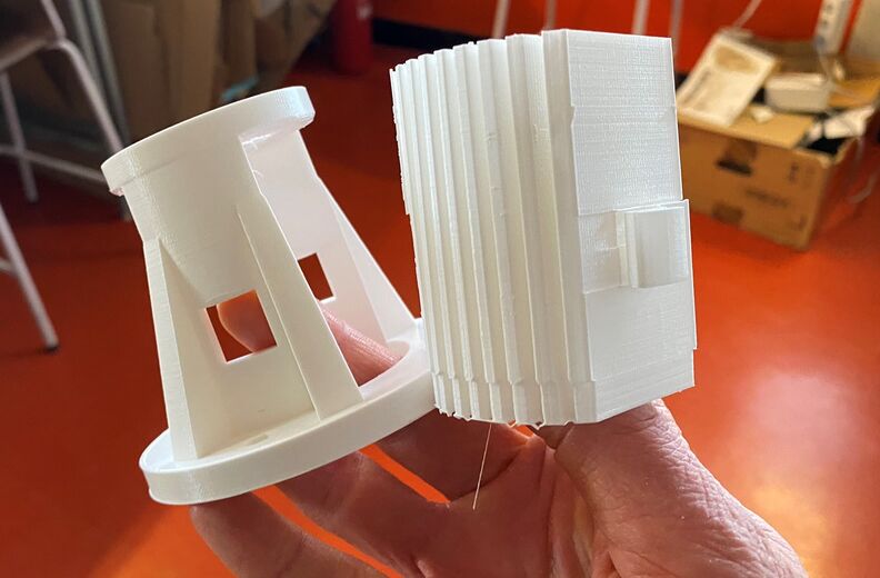 The 3D printed base for spiral 1 of my robot arm. The support material came easily away from the part in one piece. Neat!
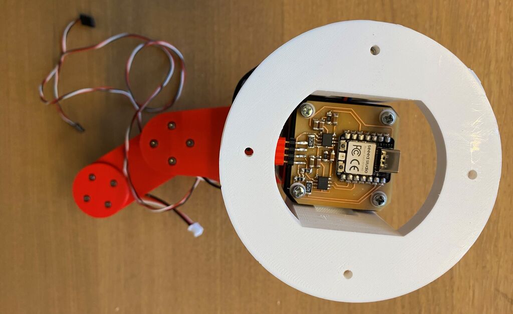 Here's the Stepper RP2040 Modular Thing that I made for the stepper in the base of the arm. Look closely and you'll see the tiny white TPU washers that I made avoid making contact between the screws and the traces.
Spiral 1 assembly
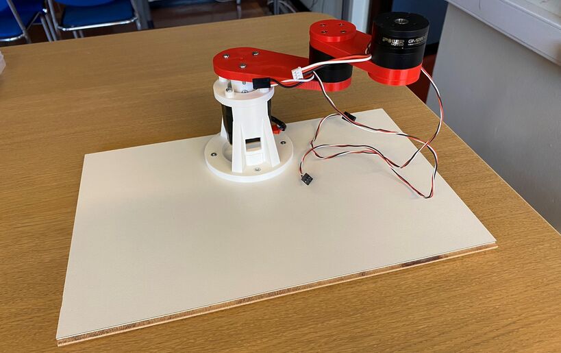 Robot arm spiral 1.
Design file
Download robot arm spiral 1 Fusion 360 model
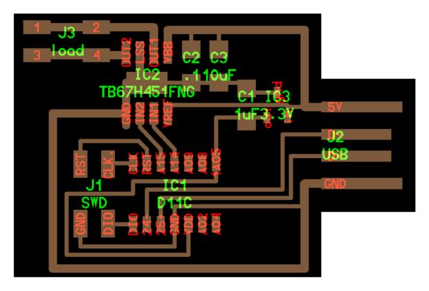
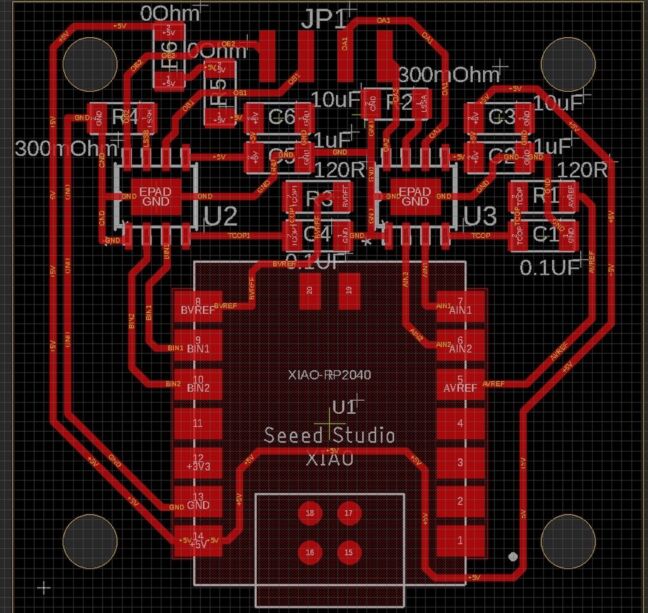
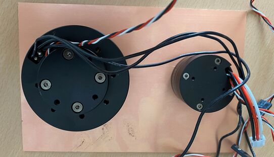
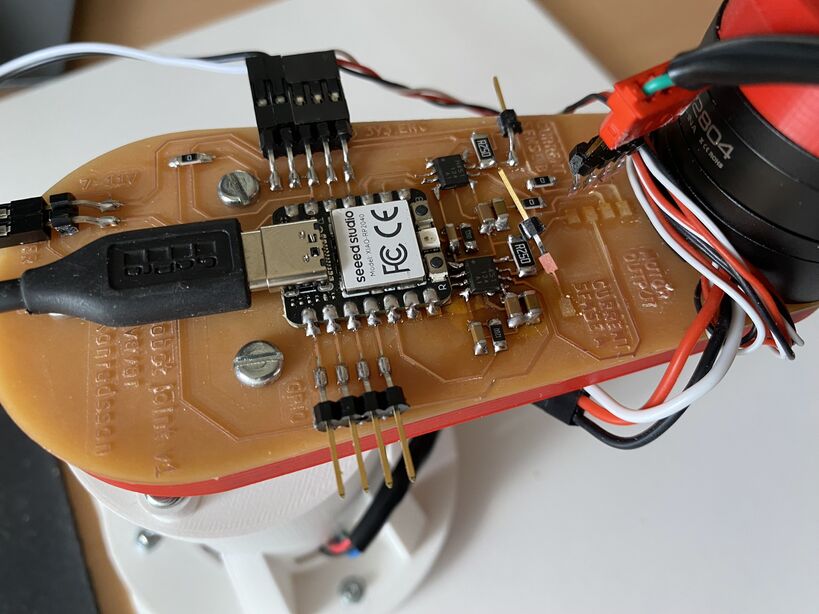
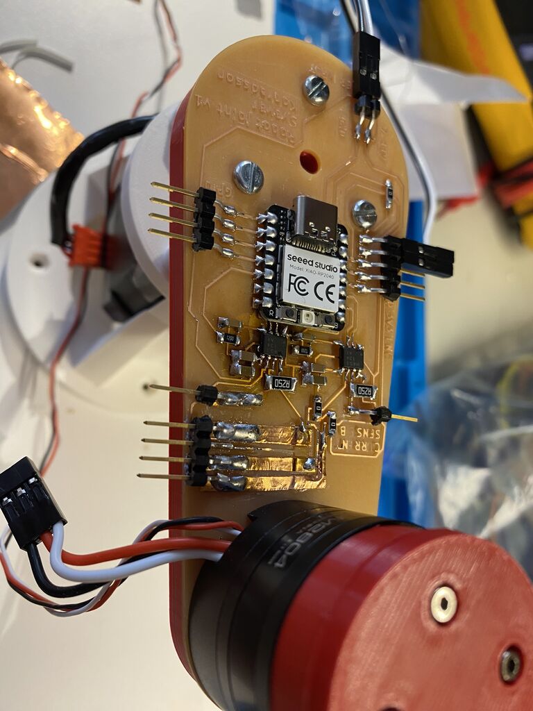
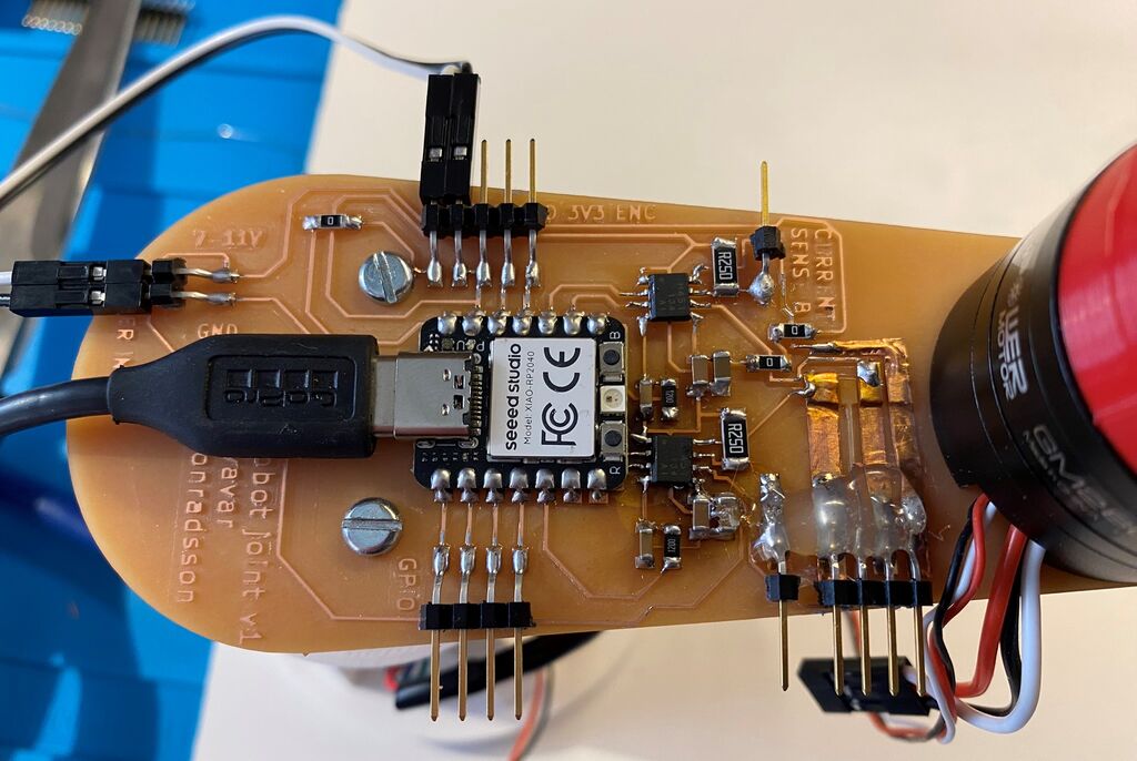
My PCB design
I heavily modified Yuichi's board, changing the shape and adding header pins, so that I could use all the Xiao RP2040's pins. I can now connect the brushless motor to the two H-bridges (it needs one and a half H-bridge) and I can connect the encoder to 3.3 V, ground and a digital pin on the Xiao.
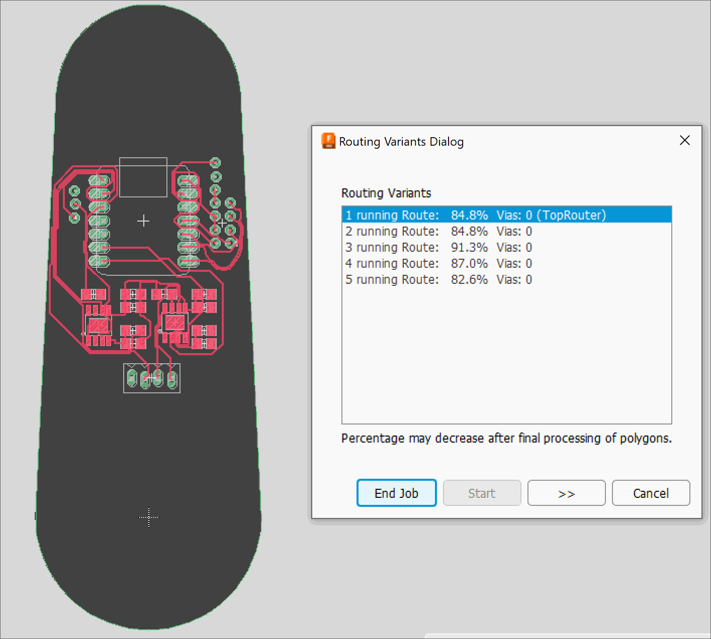 Trying the Autorouter in KiCAD. I ended up routing everything manually.
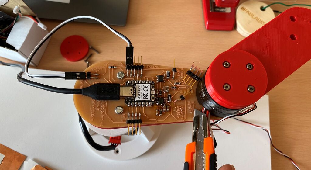
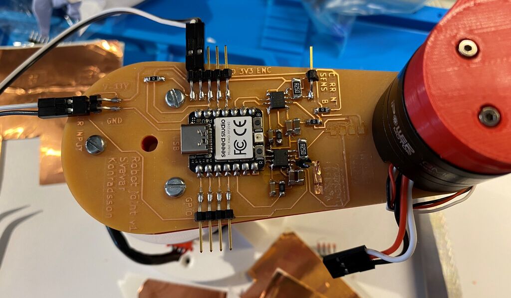
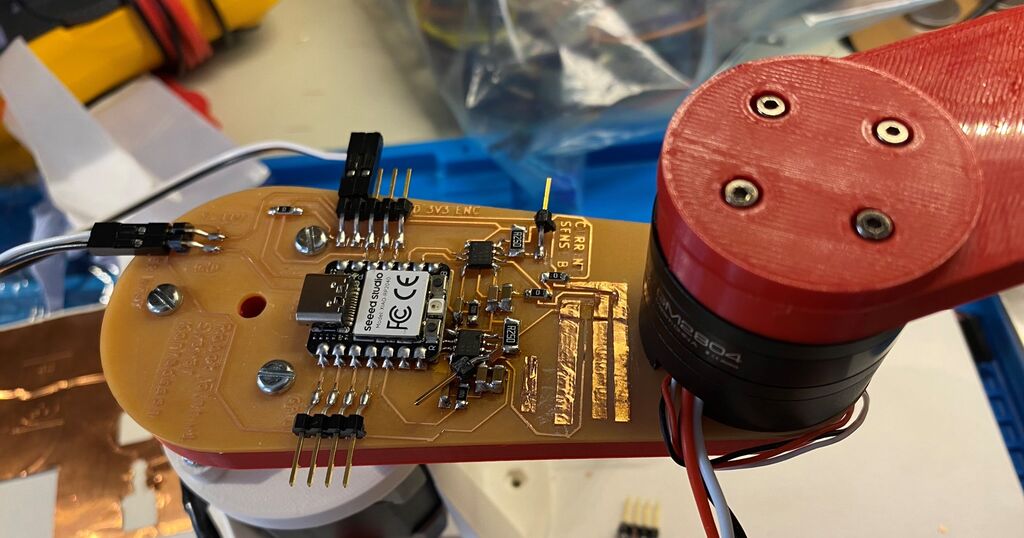
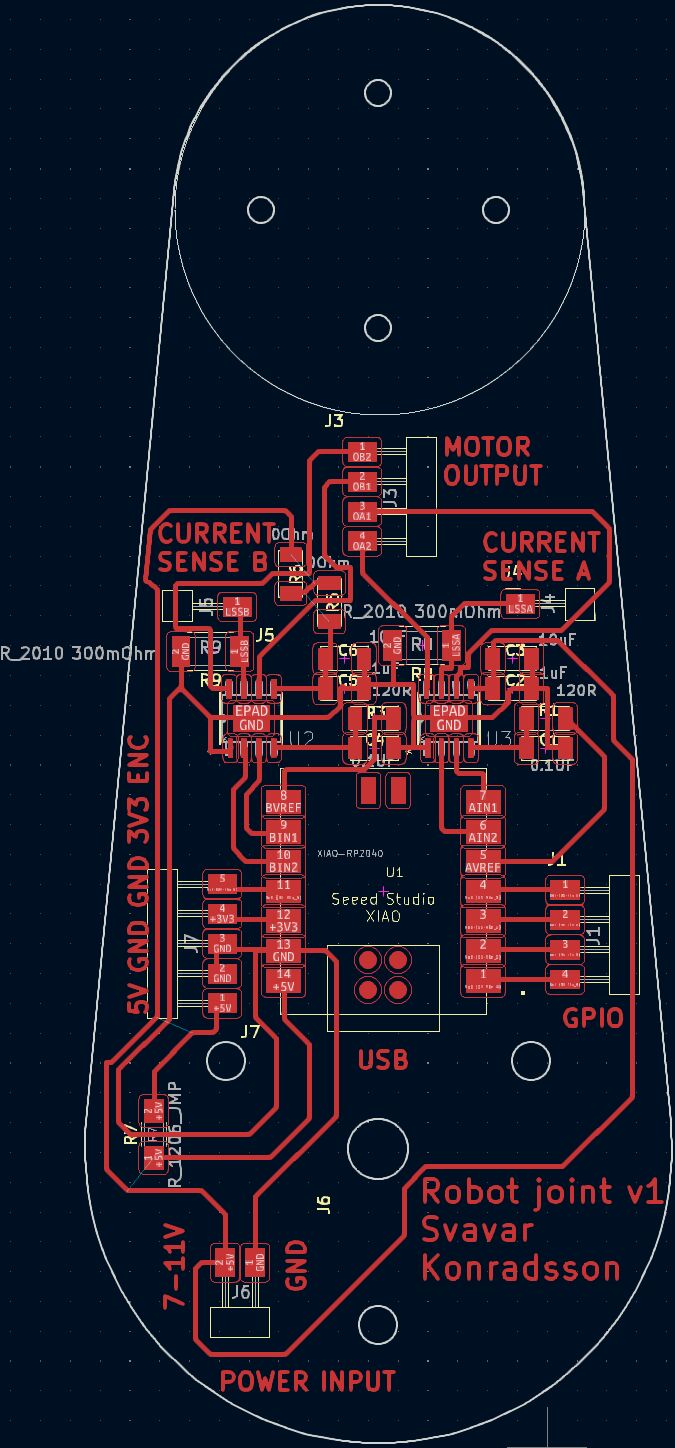 My robot joint v1 PCB.
I also added one header pin to the current sense resistor, hoping that I can read the current going into the motor. That would be very useful, because it's a way to prevent the H-bridges from overheating (I burned a motor driver on a commercial robot arm once and I want to make it impossible on my arm) and I can also use the measured current as a way to measure the force on the joint. Current sensing is not available on any hobby robot that I know of, so if this works, then it will be a great feature!
I also added a 7-11V power input for the brushless motor. Yuichi's stepper board uses the 5V USB pin to power the stepper, but my brushless motor needs a higher voltage. I will just be using a lab power supply for now. I will figure out the arm's power supply later. Does it make sense to add a boost converter? I don't know, converting 230V AC into 5V and then converting 5V into 11V sounds a bit messy to me.
Design files
Download Robot joint v1 KiCAD project
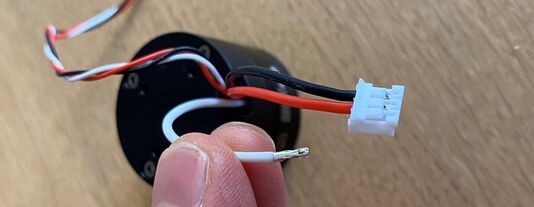
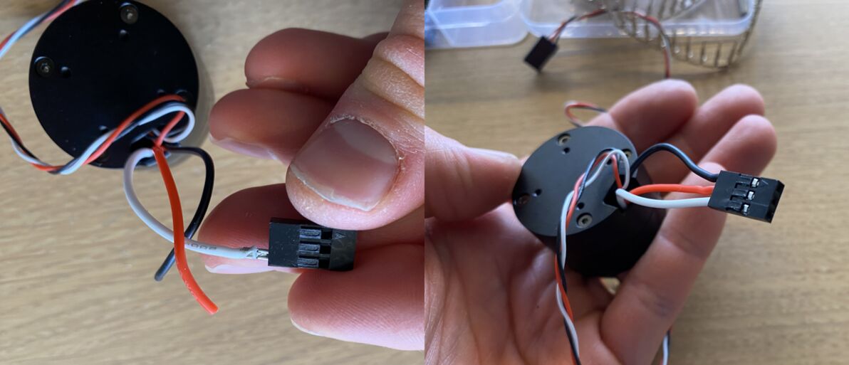
Putting Dupont connectors on the motor
The power connector that came with the motor is too small for the standard 2.54 mm pin headers in the Fab Lab Inventory, so my instructor Þórarinn showed me how to crimp Dupont connectors onto the wires.
 Small connector.
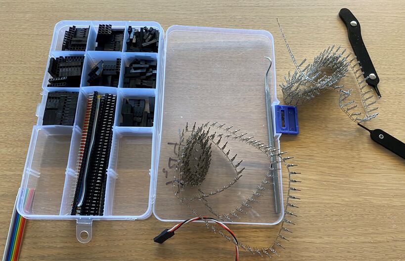 Þórarinn's Dupont connector kit.
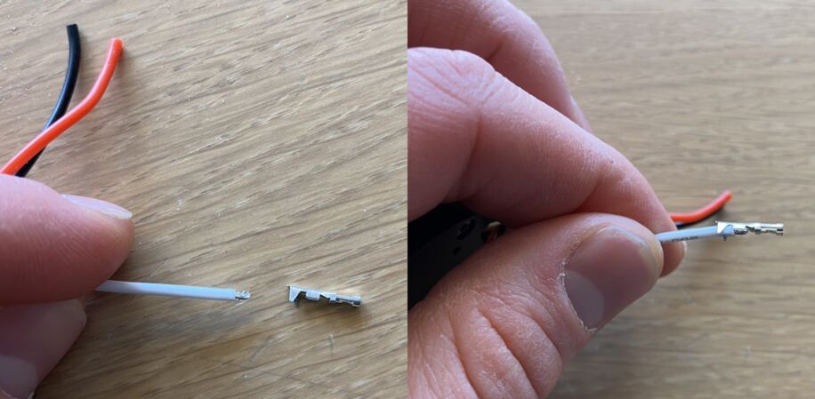 Aligning a female Dupont connector to the wire. The first crimp connection grabs the plastic cover and the second one grabs the bare wire and secures an electrical connection.
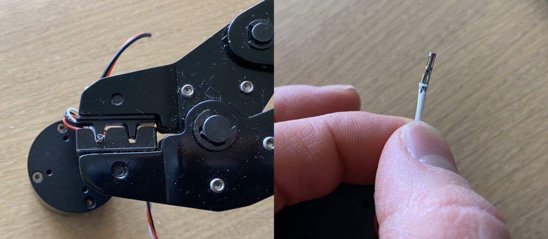 Crimping the connector onto the wire. More recently I've started to use narrow nose pliers instead. Then I can control exactly how the crimping goes and I don't waste as many Dupont connectors.
 Triple Dupont connector, ready for service.
PCB production
 Under
Under number of offsets (off screen) I typed -1, to have the milling machine clear all the excess copper off the board. I thought this was the safest move, since I'll be putting a BLDC motor with an aluminum chassis onto the board.
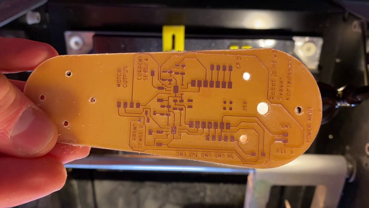 That's a nice-looking board.
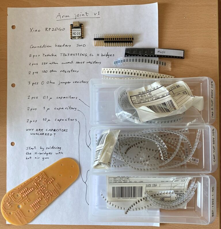 The components for arm joint v1, with a general comment on component labeling.
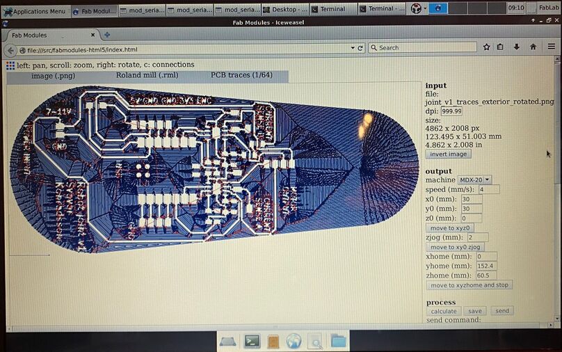
Scaling problem
The holes for the brushless motor screws were too far apart. How could that be? I exported the arm profile with the holes directly to DXF from Fusion 360, imported them into KiCAD and then exported to SVG without modifications. My instructor Þórarinn suggested that my DPI settings in Inkscape and Fab Modules might be off. If you check the Fab Modules image, you'll see that the resolution was automatically set to 999.99 dots per inch, instead of 1000.
Oh no, torn motor pins!
I tore the motor pins off the board when I was trying to insert the connector. The copper also came off the board.
 This was a design lesson: you have to put the connectors all the way at the edge of the board! I don't know what I was thinking.
This was very frustrating. I had to stop working, cool off and come back the next day. With a level head, I thought that I might actually be able to save this board using the adhesive-backed copper sheet that I use on the vinyl cutter.
The fix
 First I cut the
 MOTOR OUTPUT and CURRENT SENSE letters off the board with a box cutter.
 Then I tried cutting a strip of copper sheet and I successfully glued it onto the board.
 Copper sheet added for the other three motor phases.
 Then I carefully soldered the horizontal header pins onto the copper sheet and made a solder bridge from the sheets to the traces on the board.
 Finally I added some hot glue to add a little bit of strength.
Stepper control with my board
Driving a stepper from the Modular Things web interface using my arm joint control board.
When testing my arm joint v1 with a stepper motor, I accidentally ripped the stepper motor pin header off the board and took some of the traces along with it. A current sense header pin also fell off the board. I decied to call it quits with making stuff for the day, went to the Heimabyggð coffe house and wrote up my experiences. With fresh eyes (and a fresh espresso) at the lab the next morning, I thought of a way to fix the board. I would cut strips of adhesive-backed copper sheet and glue new traces onto the board. I soldered them to the remains of the old traces on one end and to the header pins on the other end, and after a bit of troubleshooting, the board worked!
I've tried 247, 427, 274, 472, 742, 724 - that covers all possible \(3! = 6\) combinations.
I'm getting PWM output on Xiao pins 0, 2 and 4.
Now I know that the right pins are 7, 2 and 4. I get good PWM output for the motor from pins 2 and 4 but I get the strange sawtooth output from pin 7.
Design files
Download Stepper H-bridge RP2040 Arduino code
Download Svavar stepper Modular Things JavaScript code
LED PWM test
Before trying to move the brushless motor, I checked whether I was getting a sinusoidal PWM on three output pins. I did this by outputting the motor control signals to the RGB LED that is built into the Xiao RP2040 board. I used Adrian's pinout image of the Xiao RP2040 many, many times because it contains the Arduino pin numbers:
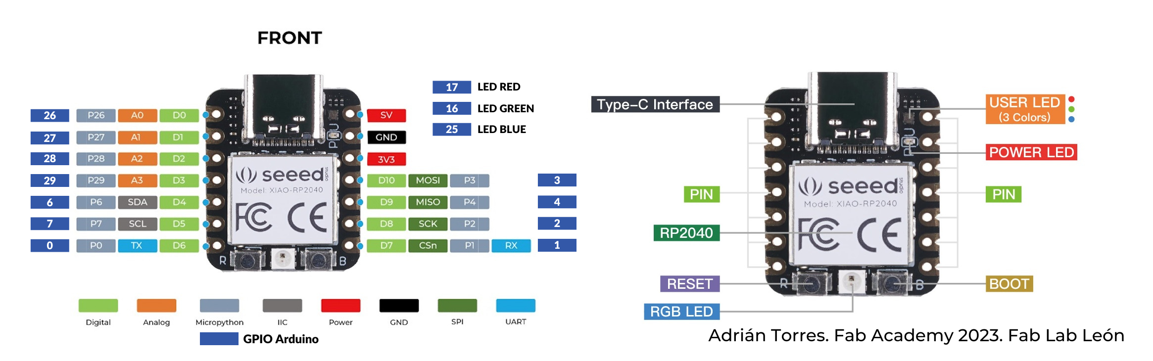 This image has been a very useful reference. To make the sinusoidal PWM motor control signals go to the RGB LED, I defined pins 17, 16 and 25 as the output pins.
Seems to be working!
Design file
Download sinusoidal PWM for RGB LED Arduino code
BLDC control with my board
Here I'm controlling the BLDC with sinusoidal PWM signals:
Getting some erratic behavior. This same code worked with the L298N stepper driver. After trying a few different speeds and voltages, I finally got the motor to spin around in circles in the last shot.
Design files
Download sinusoidal L298N brushless control Arduino code
Debugging
The brushless motor moved erratically no matter what I tried. I wondered if I had soldered the wrong capacitors onto the board. I tried to measure them with a component tester:
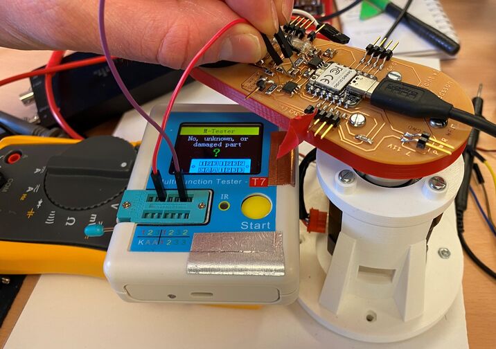 Trying to measure a capacitor with a component tester.
I couldn't get a reading with the component tester. Eventually I decided that I must have put the right capacitors on the board because I was so systematic and methodical in soldering the board.
Finally, I tried lowering the power supply voltage to 5V. The motor still worked. Then I switched the motor over to Yuichi's Modular Things stepper driver and found erratic behavior there too. It seems that this Toshiba motor driver just doesn't cut it. I then connected the motor to the ancient L298N double H-bridge and it worked! OK, so the Toshiba H-bridge is out and I need to look for an alternative.
Looking at the signals from the H-bridges. The board can control a stepper just fine. When trying to control a brushless motor, one H-bridge is a problem. It's the one that has only one pin connected. It seems that these motor drivers don't have independent half-H-bridges, which is what I need for brushless motor control. I'm going to abandon this board.
I also noticed a lot of compliance in the structure. It seems to stem mostly from the stepper coupling that I designed. This is something I can improve in the next spiral. See the arm bending here:
Measuring the power of an output device
I measured the power use of an OLED screen.
First, I measured the voltage over the component. That means that one lead of the multimeter is on the "hot" side of the component and the other lead is connected to ground on the other side. The OLED must be powered on for the voltage measurement to work.
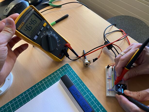 Measuring the voltage that the OLED screen gets.
Then I measured the current that the OLED screen uses. I needed to break the circuit and insert the multimeter into the circuit on the "hot" side, in order to measure the current flowing through the OLED. Inside the multimeter is a resistor with very low resistance. The multimeter measures the voltage drop over the resistor and uses that value and the resistance to calculate the current using Ohm's Law.
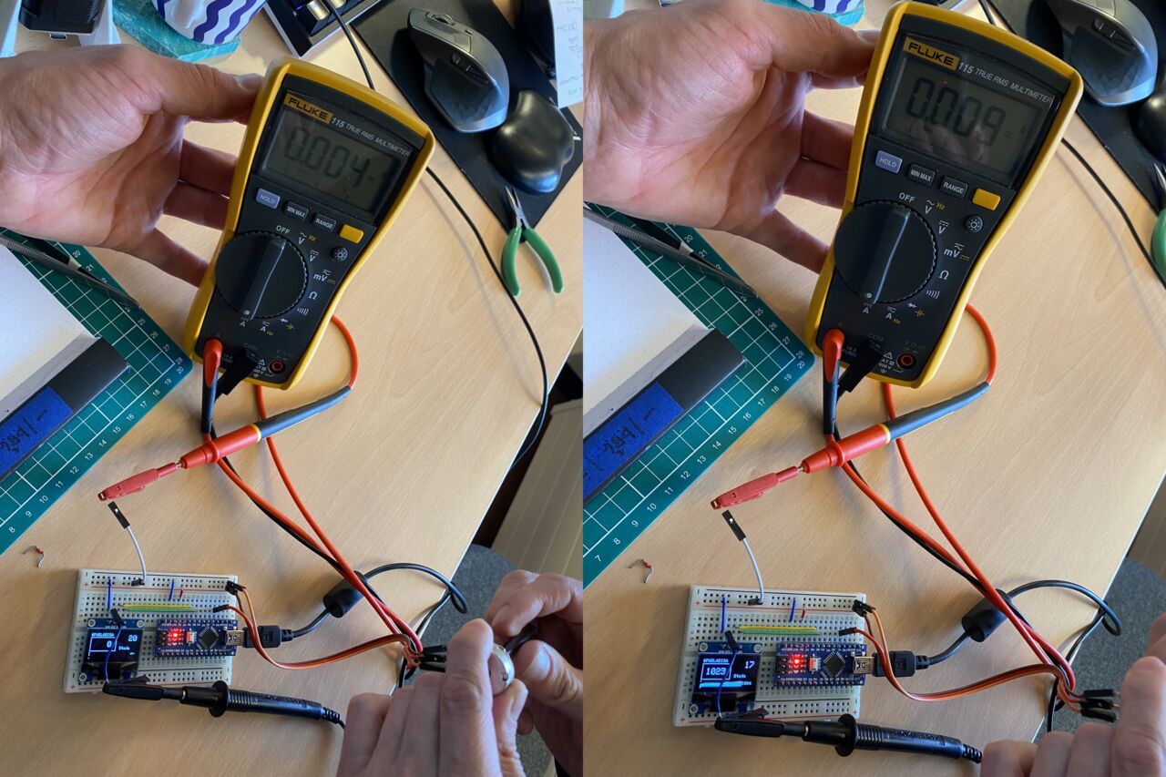 On the left, the potentiometer is turned all the way down, so the bar is black. On the right the pot is turned all the way up, so the bar is white. There is a clear difference in the current reading.
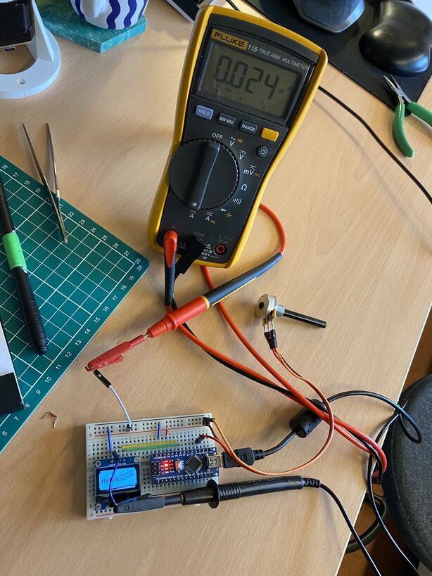 Measuring roughly the maximum current that the OLED screen uses. About 90% of the OLED screen is is illuminated here.
To calculate the power consumption, I'll use the power formula:
Potentiometer set to 0%:
Potentiometer set to 100%:
Maximum OLED power consumption: