Electronics Design 
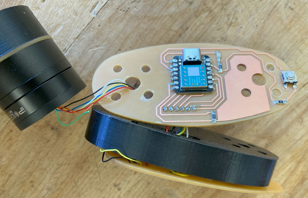
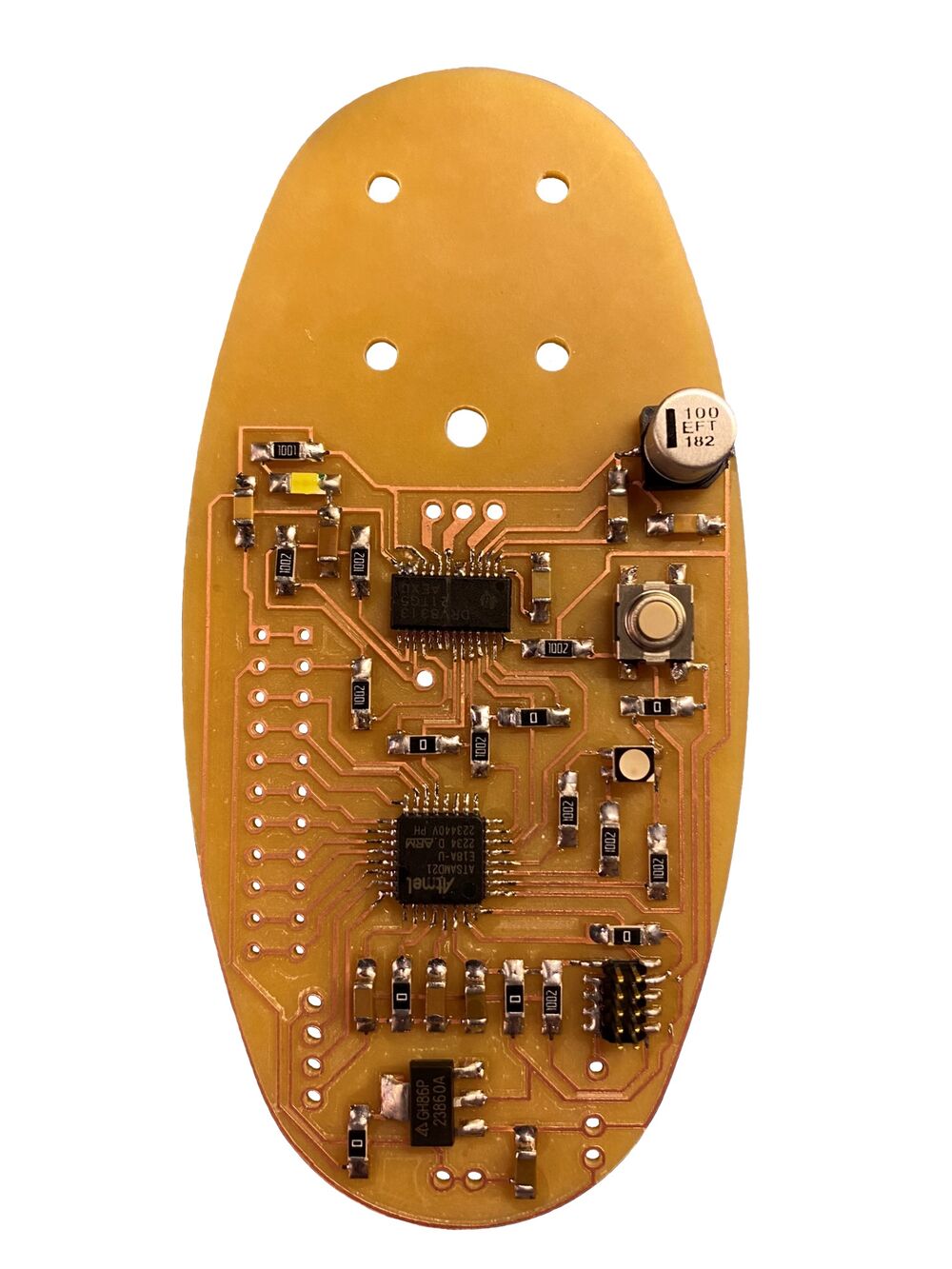 A completed Baksi board.
Since both the SimpleFOC motor control library and the OSAP network layer library were able to compile onto the SAMD21 chip by pretending that it's an Arduino Nano 33 IoT, that's what I'm going with. Now I need to go into the schematic of this Arduino to see its pin definitions:
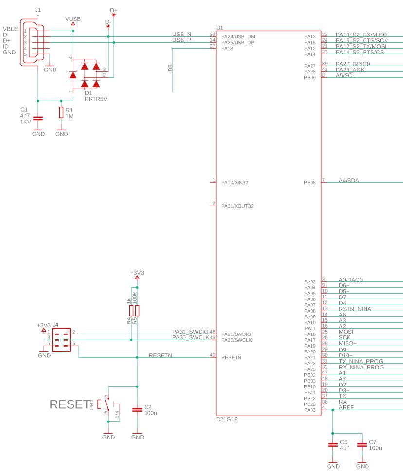 The Arduino 33 IoT schematic. Let's see what we have here.
The SPI communication wires from the AS5048 magnetic angle sensor are as follows:
black, pin 1, CSn
blue, pin 2, CLK
yellow, pin 4, MOSI
green, pin 3, MISO
red, pin 11, VDD5V
white, pin 13, GND
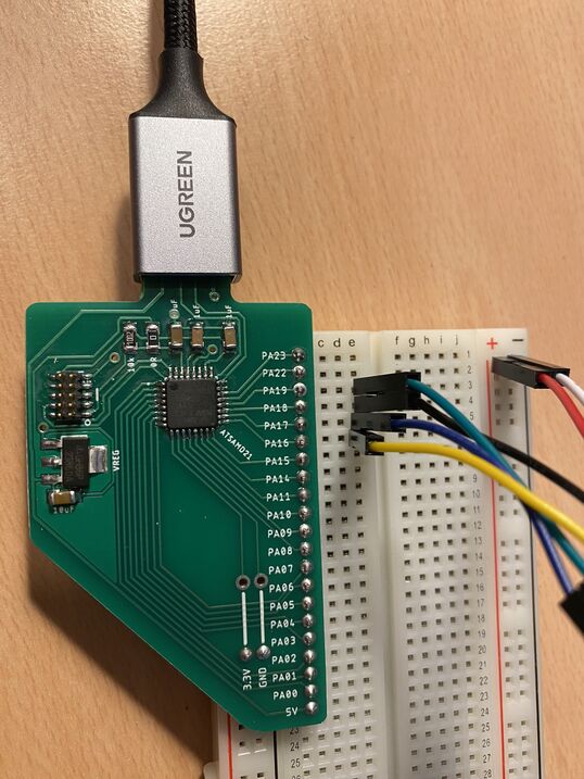 SPI connections to the breadboard Modular Thing.
Let's start with MOSI. That's pin PA16 on the Arduino Nano 33 IoT. I'll put the yellow wire there on the breadboard Modular Thing. Then MISO is pin PA19. I'll put the green wire there. Through all this tinkering I've learned that CLK is the same as SCK. That's pin PA17 and the blue wire goes there. Csn, or the chip select pin, can be assigned to any digital pin. I'll put on PA18 (the black wire). Then all that's left is +3.3 volts and ground.
And here's the test:
I'm getting an angle reading in the serial monitor! How cool is that?
OK, let's connect the motor driver. For that we need PWM. According to the schematic above, the PWM pins on the Arduino Nano 33 IoT are as follows:
| Arduino | 2 | 3 | 5 | 6 | 9 | 10 | 11 | 12 | 16/A2 | 17/A3 | 19/A5 |
|---|---|---|---|---|---|---|---|---|---|---|---|
| SAMD21 | PB10 | PB11 | PA05 | PA04 | PA20 | PA21 | Not on schematic | Not on schematic | PA11 | PA10 | PB09 |
On the the breadboard Modular Thing I only have access to PA pins. Let's try PA4, PA5 and PA10 for PWM and PA6 as the enable pin. In the Arduino code I'll set pins 6, 5 and 17 to output PWM and let pin 7 be the enable pin.
After uploading the angle_control.ino sketch, the motor twitched a little bit and I got the following messages in the serial monitor:
MOT: Enable driver.
MOT: Align sensor.
MOT: Failed to notice movement
MOT: Init FOC failed.
Motor ready.
I must have mixed up some of the motor driver pins. Let's add my LED testing board to the circuit:
 No PWM on the brown wire.
The enable pin turns on first (white wire) and then PWM starts on the yellow and orange wires. The brown wire (the third BLDC phase) gets no PWM signal. Aha! I still have digital pin 9 in the code, which applies to PA20! That's how I first wrote the code, but I then discovered that PA20 isn't broken out on the breadboard Thing. Alright, I'll change the third PWM pin from 9 to 17, which matches PA10, and see what happens.
Now I'm getting PWM signals on all three phases, but the motor shakes like crazy. I wonder if I accidentally wired the phases in the wrong order. Nope, that isn't helping. I'll try removing the LED test board, since I'm done with that for now. And that was all it took! I have a smooth, responsive servomotor controlled by a bare SAMD21 chip! I won't upload a video of that, because my repository is getting quite big.
This is it. Now I can design my board.
PCB schematic design
I added some electronic parts to a blank schematic. I used the RGBB Modular Thing as a reference design, to see which passive parts the microcontroller needs. I want to have an RGB status LED on the robot's 'forearm' and also a button to disengage the motors and record movements.
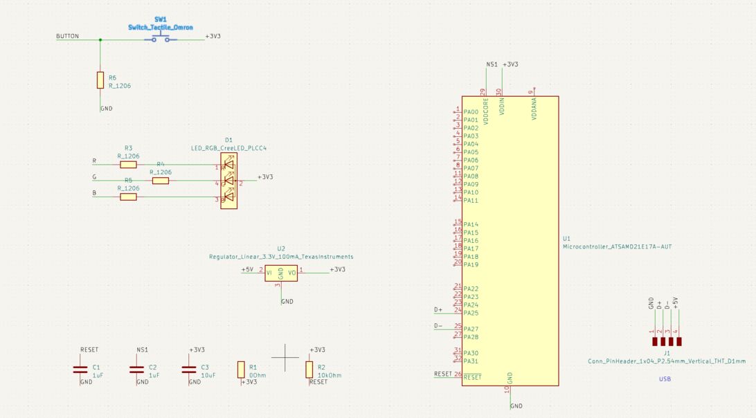
I can see that the Modular Things follow the SAMD21 datasheet and put a 10uF decoupling capacitor on VDDIN (the +3.3V input voltage) and a 1uF decoupling capacitor on VDDCORE (the 1.23V core logic voltage of the chip, provided by an internal regulator):
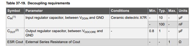 I don't know what decoupling capacitors do, but it's nice to verify the design using this table in the microcontroller datasheet.
Then I started on the motor controller. I used the SimpleFOC Mini as a reference design. One of the goals of the SimpleFOC Mini is to:
Make it in a way to be a minimal working example for users that are interested to build their own boards based on the DRV8313 chip.
-Antun Skuric, creator of the SimpleFOC library
The SimpleFOC Mini is a two-layer board, but I want to make a one-layer board. Fortunately I'm not using all the pins on the motor controller, so I can simplify the design:
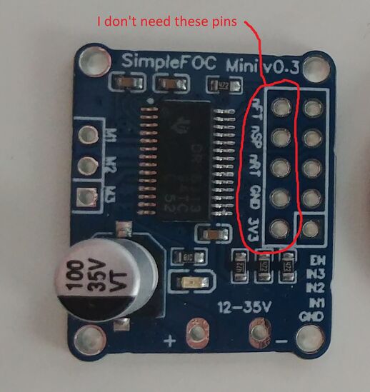 The DRV8313 motor driver has a 3.3 V regulator to run a microcontroller, but it only supplies 10 mA, which is not enough for me. So I'll skip that pin.
On second thought, after reading about the pins that I haven't been using, I'm changing my opinion. I would like to be able to
The DRV8313 motor driver wasn't in the KiCAD library or in the fab library, but I found it on SnapEDA. But I quickly ran into a problem with it:
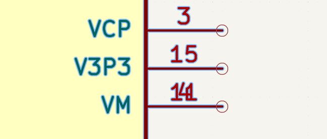
Pins 4 and 11 are superimposed. They are both VM, but on the SimpleFOC Mini schematic, they are connected differently. So I needed to right click the symbol and select Edit with Symbol Editor. Fortunately, all I had to do there was to move one of the pins:
I also moved the three superimposed GND pins apart, so that I could read the pin numbers.
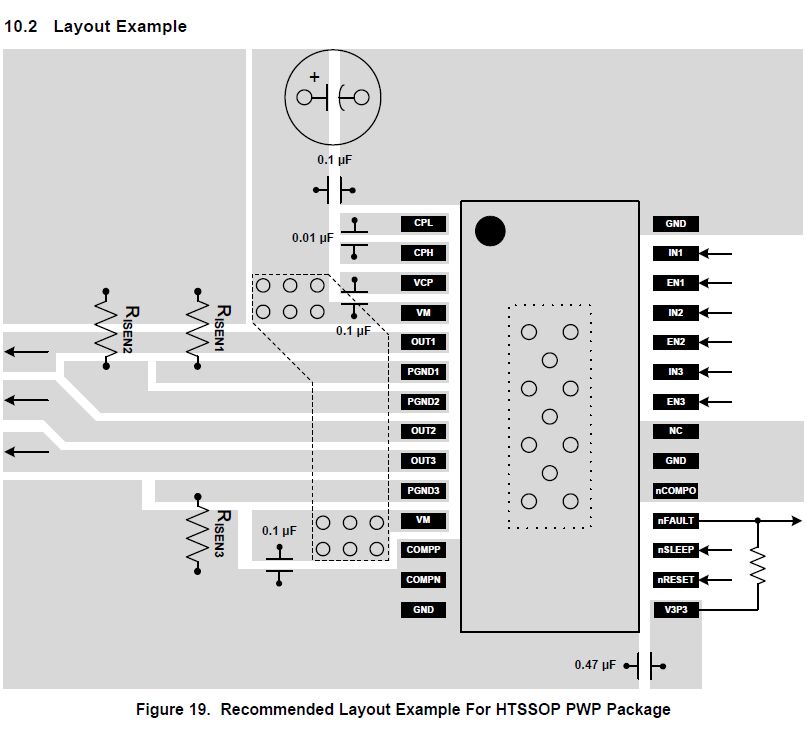
I used this layout example heavily when reviewing my design.
PCB routing
I had to put eight jumper resistors in order to route this board on one layer. I also route the USB, power and SPI wires through the 3D printed layer that is sandwiched between the two PCBs in each joint. I look forward to redesigning the board for manufacturing at a board house, with 2-4 layers. That should make things considerably easier. But I am glad that I managed to design a version of the board that can be made in any Fab Lab on a single-layer PCB, because not everyone is skilled at making double-layer PCBs (myself included).
 Let's just put a wire that goes on the back side of the PCB. No one will know.
PCB design review
Now let me go over the schematic and PCB layout and see if everything checks out:
Microcontroller
- USB (I didn't check whether the data lines are equally long. Let's hope for the best!)
- 3.3V regulator (PCB layout didn't match schematic, fixed now)
- Button
- RGB LED
- JTAG programming connector and associated passive components (Oh no: SWDCLK trace is routed under JTAG connector! Looking at the JTAG connector, this seems impossible. Time for another jumper resistor.)
- SPI connections to the magnetic angle sensor
- Decoupling capacitors for the microcontroller
- Rest of the microcontroller connections
Motor driver
- Motor power input
- Power indicator LED
- FAULT, RESET and SLEEP on the motor driver
- Bulk capacitor and bypass capacitors for motor (One bypass cap wasn't connected to ground! Fixed now.)
- PWM signal wires between microcontroller and motor driver
- ENABLE wires and resistor
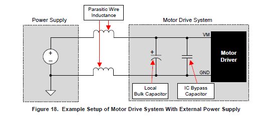
- Rest of motor driver connections (Two motor outputs routed under jumper resistor. Not good. The two VCC pins on the motor driver weren't connected together. They clearly need to be, according to the layout example. Fixed with a trace underneath the BLDC motor. Must remember to cut some vinyl to insulate the motor from this +10V power trace. The layout example has resistors going between ground pins. The SimpleFOC Mini schematic has no such resistors. It worked on the breadboard, so I'll skip the resistors. I've run out of room on the PCB! One more thing that I changed from the SimpleFOC schematic, is that I'm connecting COMPO to ground, as the motor driver datasheet shows. I also tried to connect NC to ground, but NC means Not Connected and it doesn't want to connect to anything. Both the datasheet and the SimpleFOC Mini schematic connect the +3.3V output from the motor driver to FAULT, RESET and SLEEP, to pull them up. I just don't have space for that. I'll just mill the PCB and if the 3.3V supply from the microcontroller doesn't do the trick then I'll just have to solder a wire to the board afterwards. Let's go!)
I had to stop milling the board and start again, because I forgot one of the comments I made in the last item on the Motor driver checklist. A very important comment that I've now italicized. So I fixed the PCB layout as follows:
 I realized that after going through the checklist and making the necessary changes, I didn't need those two jumper resistors anymore. I was also able to move the VCC track out from underneath the motor.
Final design
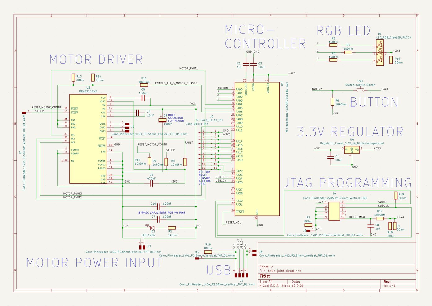 The baksi robot joint schematic.
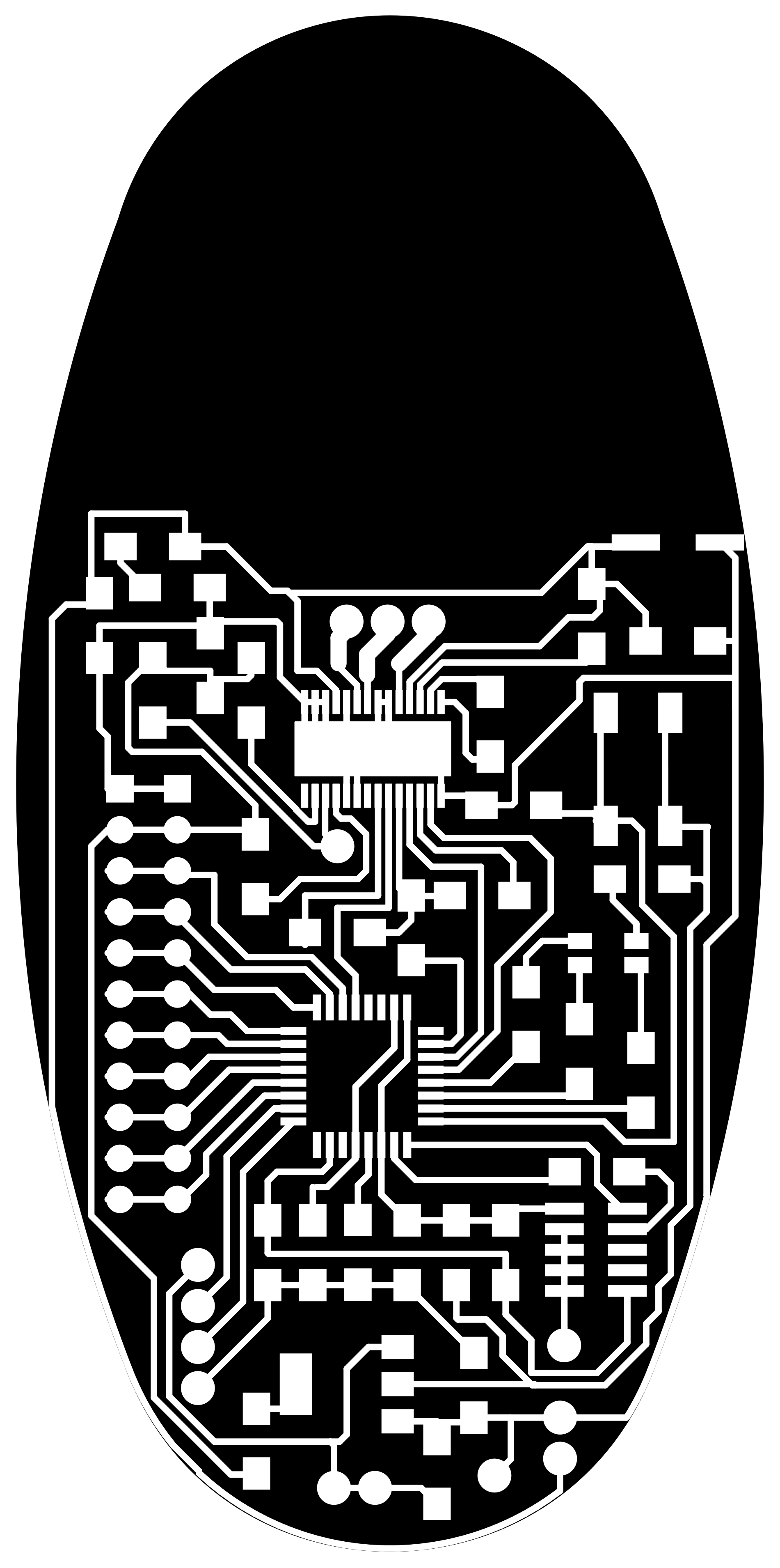
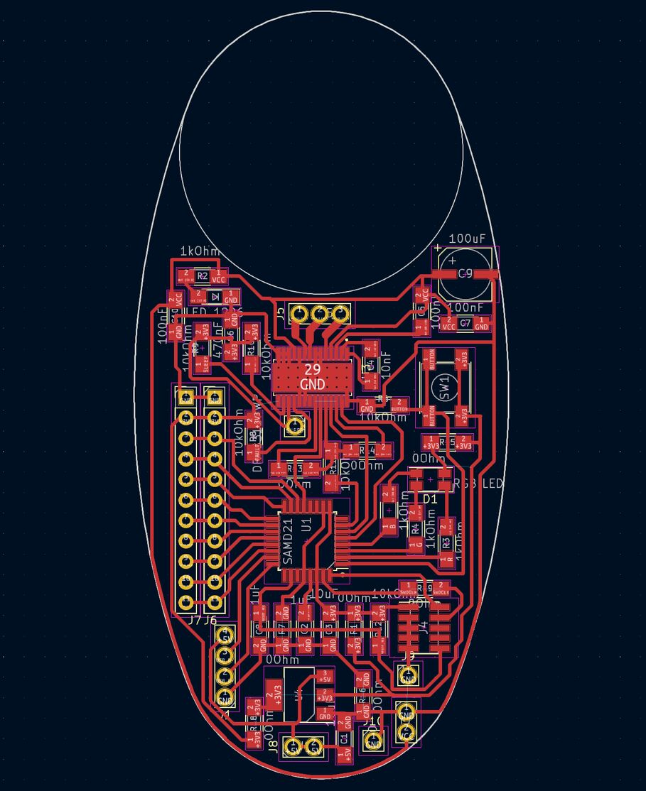 The baksi robot joint PCB layout.
PCB production
My first attempt at milling the PCB failed, and I broke the smallest end mill (the 0.01" one). I only have one left now. Looking back, I made the fundamental mistake of not making a small test of the most challenging aspect of the process. I'm going to try a V-bit now.
When soldering the teeny tiny DRV8313 motor driver onto my beautiful board, I found that its legs are very thin and flexible, and so when you've fastened the driver to the big ground plane with a heat gun, you can bend the legs into place, as long as they're close to their intended copper pad.
After soldering, I successfully put the bootloader on the SAMD21 chip and then programmed it with the SimpleFOC code. But I got no reading from the magnetic angle sensor and the serial monitor said that it detected no movement from the motor. The motor sounded weird.
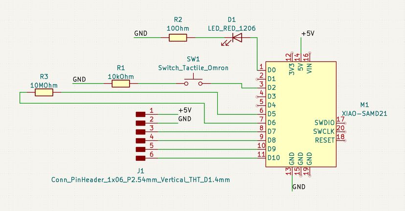
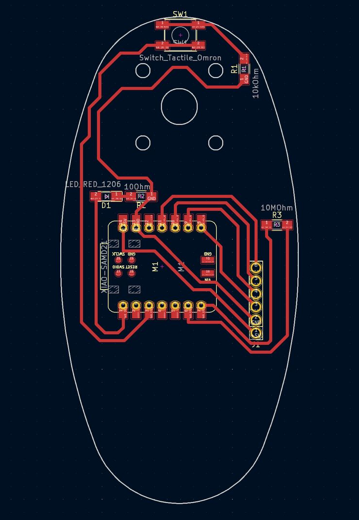
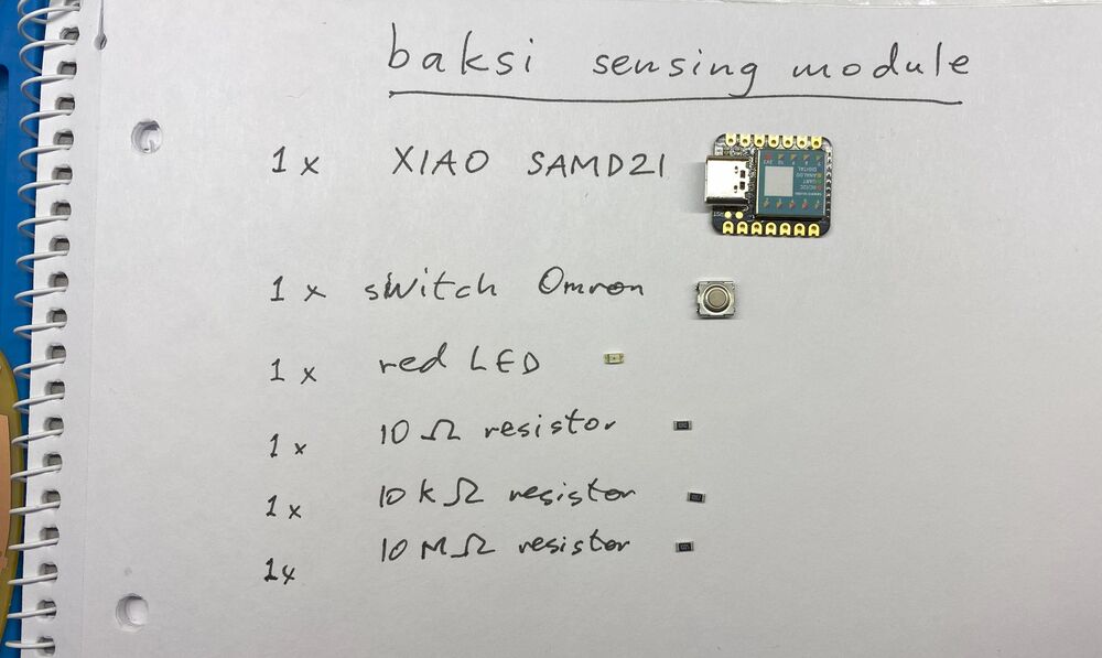
Sensing board
I also made a sensing board for Baksi. It contains an endstop button for the Z-axis as well as a capacitive step-response proximity sensor, so that it can sense when a human gets too close, and stop moving. The big copper area on the board is the proximity sensor. The board has a Xiao SAMD21 module, which has nice analog-to-digital converters.
I had a little trouble finding the right pin names for the Seeeduino Xiao SAMD21. In the first place, when I first connected it, it was set up as a Seeeduino Femto. I couldn't find much info on that online. I tried uploading an Arduino sketch to it as a Seeduino Xiao SAMD21, but it got bricked and didn't show up on my computer anymore. Not in the Arduino IDE and not in Device Manager either.
After a bit of Googling I found the solution to this problem. I shorted the connection between the RESET pads on one side of the Xiao's USB connector and it immediately appeared on my computer as a UF2 drive. I then tried uploading the same Arduino sketch to it as a Xiao Femto, and it worked.
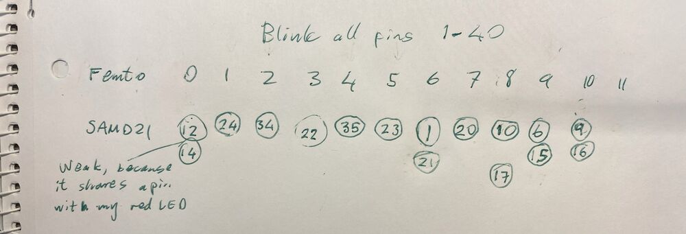
But what's the pinout of the Xiao Femto? I tried the Xiao SAMD21 pin numbers but they didn't work. I also tried my Blink all pins sketch, where I make every pin from 0 to 40 blink once and write its number to the serial monitor at the same time.
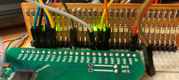
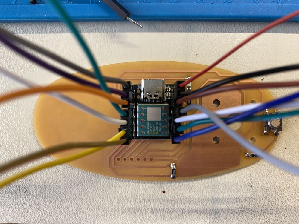 I connected each pin to an LED on my LED debugging board to discover the pin numbers.
But now the problem was that after uploading, the device disappeared and so I couldn't get data from it through the serial port. So I tried blinking the LED as many times as the number of the pin that I was testing, After a good wait, I counted twelve blinks on my red LED. Here's a video of my debugging method:
I've discovered pin number 6!
Here are all the pin numbers that I wrote down (I recorded a fourteen-minute long video and played it back to get all the pin numbers):
Is there a similarly simple way to find the pin numbers of my button and capacitive sensing pad?
The sensing board is integrated into Baksi but it doesn't turn on. I seem to have misunderstood how the power works on the Xiao module. I thought that I could power it through the 5V pin, but that seems to only offer 5V out. I probably need to change the connections and power the Xiao through the USB connector. This is where Baksi's sensing board stranded.
Design files
Download baks_joint2_traces.png