Computer-Controlled Cutting 
Assignment
Group assignment
- Characterize your laser cutter's focus, power, speed, rate, kerf, joint clearance and types
Individual assignment
- Cut something on the vinyl cutter
- Design, laser cut, and document a parametric construction kit,
- accounting for the laser cutter kerf,
- which can be assembled in multiple ways,
- and for extra credit include elements that aren't flat
See more info and recording of the lecture here.
Parametric construction kit
Design
I wanted to make a minimal parametric construction kit that was made up of only one piece. You can see the design taking shape in the hand-drawn sketches below as I was thinking about the design specifications. When I had decided on the specs, the design was fully defined. The piece can have no other shape.
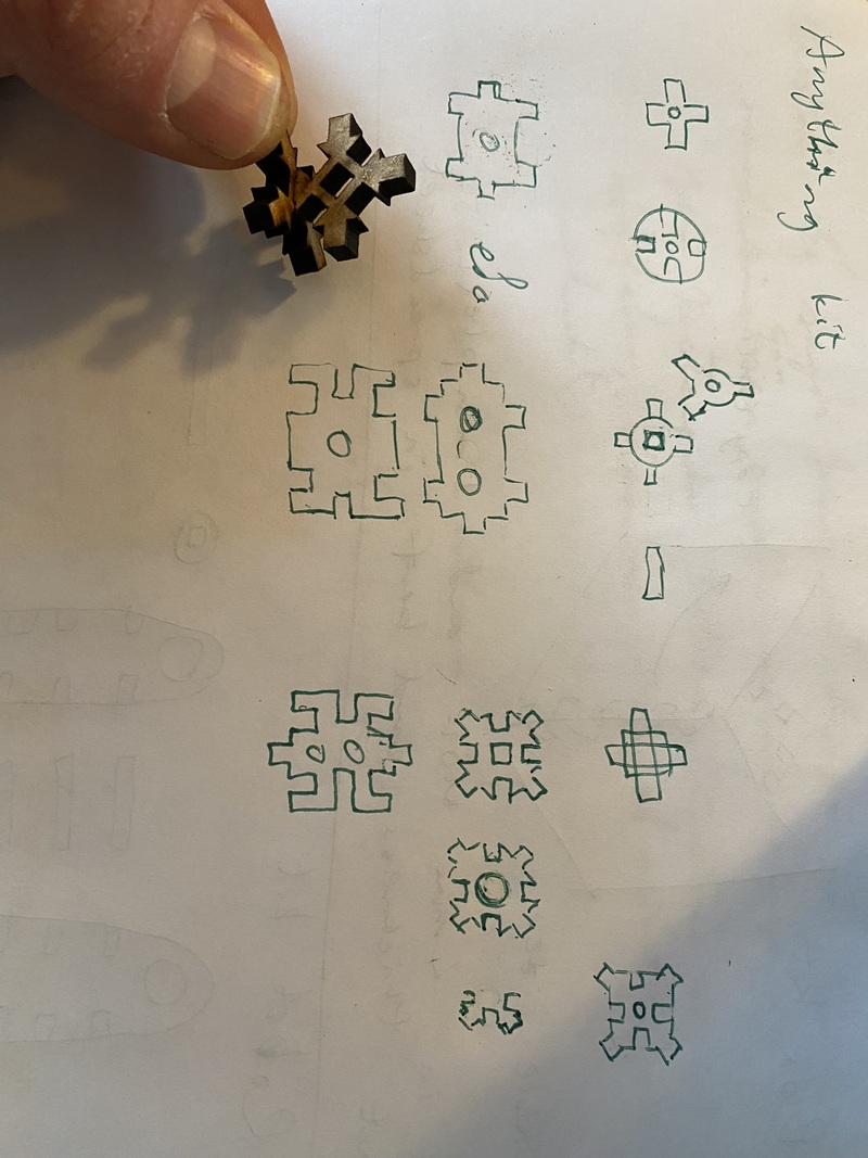
I wanted four pins and four pockets, so that defined the shape of the piece. The plan was to have the dimensions of the pins and pockets equal on all three axes, so that the pieces can be assembled every which way. This ultimately means that all the dimensions in the 2D sketch are controlled by the material thickness.
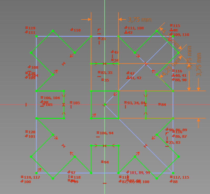
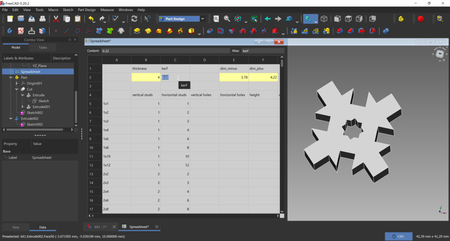
I made a sketch in FreeCAD and set up a spreadsheet inside the part file. In the spreadsheet I defined two main parameters that I use to control the design; the material thickness and the kerf. There I am editing the value of the kerf:
I made two test pieces (see the image at the top of the page) and decided to make the hole in the middle a star instead of a square. That way you can assemble the pieces at a 45° angle, which is necessary because the angle between every pin and pocket is 45°.
Laser cutting the pieces
Then I made a series of kerf tests, which was easy because I only needed to change one parameter. I wound up making the fit tighter than I usually do (kerf = 0.24 mm) because the fit is tighter when the pieces are assembled in-plane than when they are perpendicular to each other. The 90° perpendicular fits were always too loose and I didn't understand why.
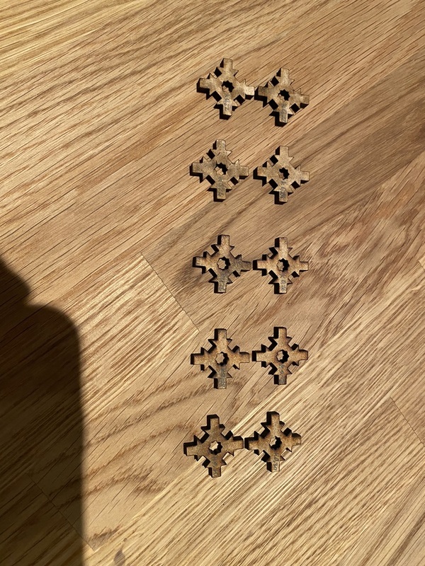 Kerf tests
Then I thought about the way that the kerf tapers, so that more material is removed at the bottom of the material than at the top surface. This is because the laser has only one focus point, which is set at the top surface of the material. Below that point, the laser beam diverges, causing the sides of the pieces to not be completely perpendicular to the surface of the sheet.
My instructor Þórarinn said that there isn't really anything we can do about that, so I tried setting the focus in the middle of the material, by focusing on a 2 mm thick sheet and then cutting a 4 mm thick sheet. I was hoping that the cut would have more of an hourglass shape than a simple taper, but it didn't work out that way. Changing the focus didn't make that much of a difference, but I ended up cutting all the pieces with it set in the middle of the material.
Here's a full plate of construction pieces, patterned by hand in Inkscape:
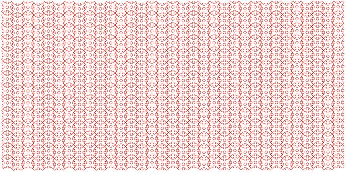
I used the Epilog Mini 24x12 laser cutter to cut my construction kit. In Inkscape, I set the line width to 0.02 mm and made the lines red (RGB 255,0,0). This is the code that the Epilog laser driver uses to determine that it should cut these lines. Then I export the drawing to PDF.
On the computer next to the Epilog laser cutter, I open the PDF document and select File -> Print.
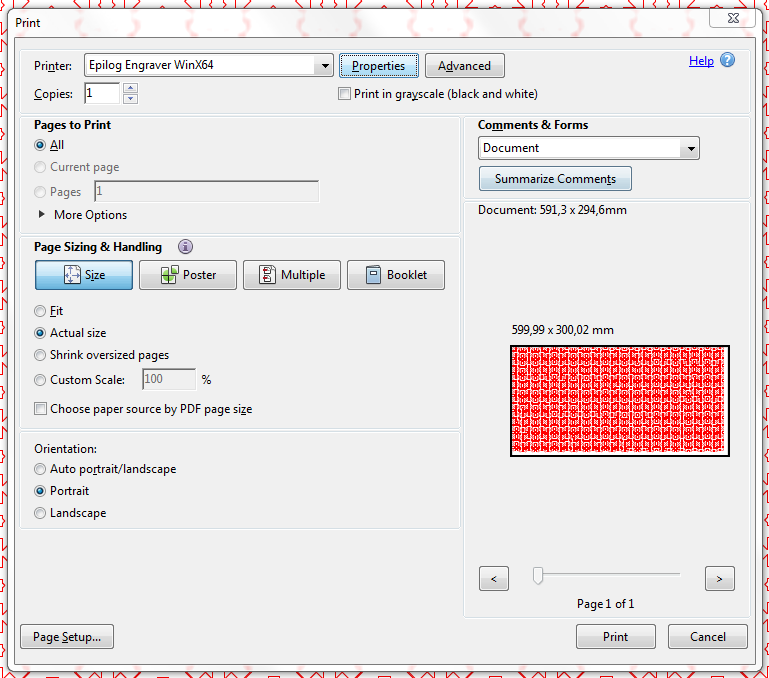 It doesn't really matter whether I select only Vector or Combined, because the document contains no raster (engraving) features. I set the Piece size to 600 by 300 mm. I only need to set the Vector settings in the bottom right corner because there is no rastering.
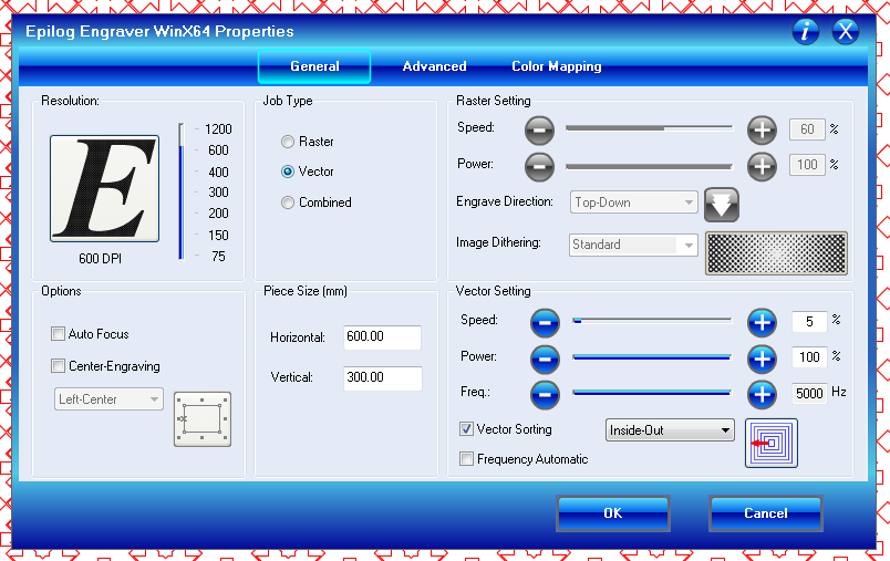 I used vector (cutting) settings of 5% speed, 100% power and 5000 Hz laser frequency.
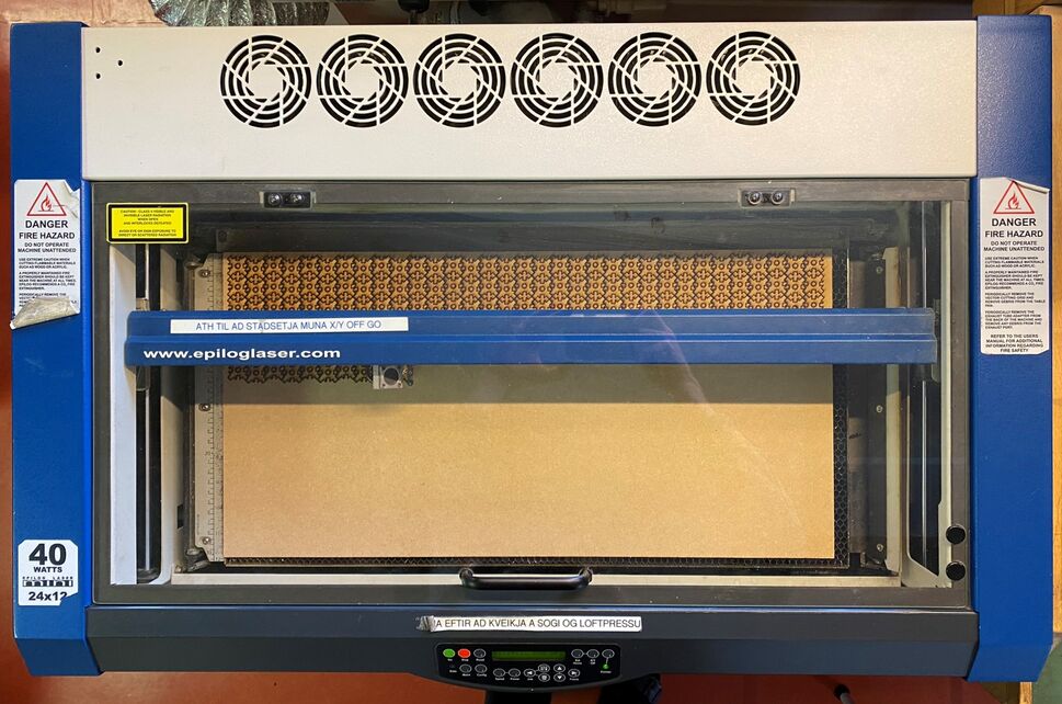 The Epilog Mini 24x12 hard at work.
Playtime
The construction kit was very well received by my family. After an evening of play, these are the resulting shapes. Wall-E, a drone, an axle with wheels, a cube, a coaster, a giraffe, a magic wand, an I-beam, and a tool to measure the curve of your spine. It works really well, it might be a handy tool for physiotherapists.
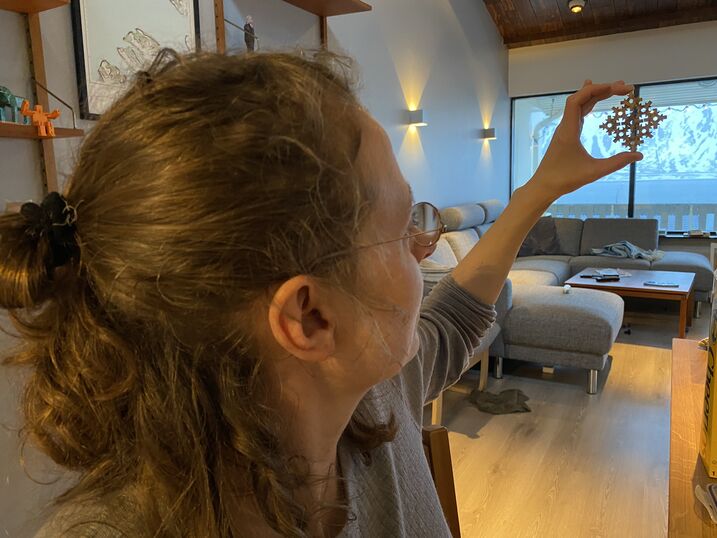
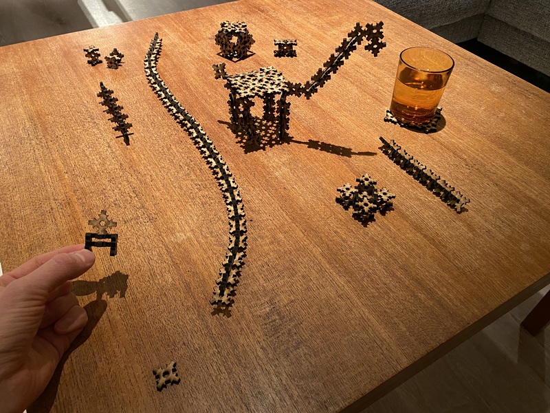 I'm holding up Wall-E, which my older son Ernir (4 years old) made.
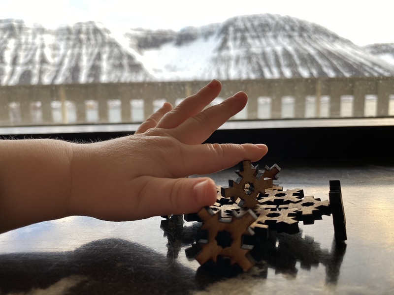 Here's Hjörtur's (1 year old) hand touching something that my wife Aðalbjörg made.
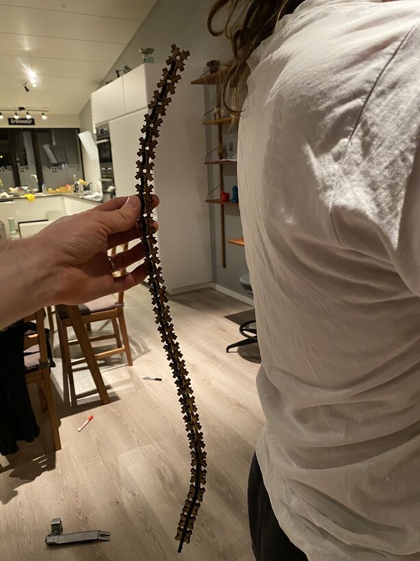 This could be a template to measure spine curvature.
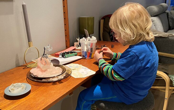 Ernir playing with the laser cut pieces and coloring some of them with a marker. Incidentally, I later melted down the rest of the Icelandic cat candle in this picture to make the FMCU button.
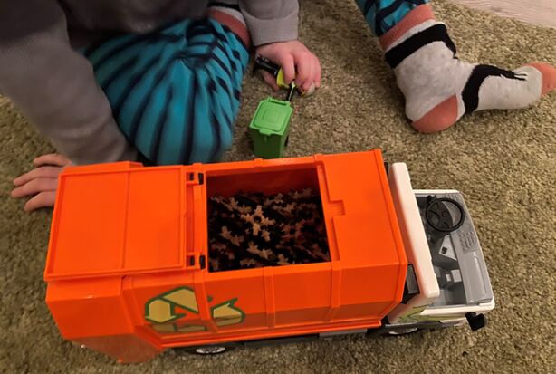 My son was also quick to start using the laser cut pieces with his beloved garbage truck.
 My wife looking through a sheet of laser cut pieces.
Design files
Download spreadsheet-driven FreeCAD design
Download SVG cutting file (462 pieces)
Download PDF cutting file (462 pieces)
Circuit cut with vinyl cutter
I wanted to cut a copper sheet and make a circuit in the vinyl cutter. This hasn't been done before at my lab. I wrote it up for my secondary school students in Icelandic and had them make vinyl cut sensors the week after I tried it myself.
I got the design for a simple step response sensor from Hafliði who was working at Fab Lab Reykjavík.
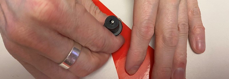
My instructor Þórarinn led me through the ins and outs of the vinyl cutter. He disassembled the knife to show me the tiny bearing that needs to be cleaned and lubricated when it jams:

Then he explained the way to adjust the knife. You start by retracting the knife fully and then cutting manually into the material. If nothing happens, you extend the knife a little bit and cut again. You want to cut fully through the material and scratch the backing, but you don't want to cut through the backing. Then you would damage the rubber that is underneath, and that's part of the machine.
You cut tabs like you see below and then bend the material and see if they come loose. When it looks like you're getting close, you start paying attention to the ticks on the knife. A course adjustment is two ticks, a fine adjustment is one tick. If the material comes loose when you bend it, but you're not cutting deep into the backing, you're golden:

Þórarinn suggested a methodology of testing to get good cuts in the copper. First I would adjust the knife as discussed above. The next step would be to vary the cutting force and the speed until I get a good result. However, after he adjusted the blade and the force for the regular vinyl, I made a test and it cut quite well through the copper! So the systematic testing ended up being just three tests.
The first test didn't work out because the copper was crumpled on top of the backing. The second test I cut with 90 grams of force and it was almost there. The third test I cut with 120 grams of force and it looked good.
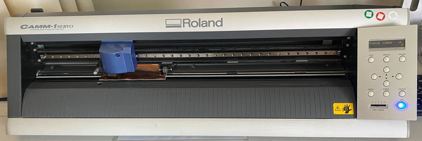 The Roland CAMM-1 Servo GX-24 vinyl cutter. I used a force setting of 120 grams to cut the copper sheet.
We use a very simple interface for the vinyl cutter; a printer driver. We export a PDF file from Inkscape with 0.01 mm thick red lines (RGB 255,0,0) and open it in Adobe Reader. I simply go into File -> Print to cut the file on the vinyl cutter. There's only one thing I need to adjust, which is the cutting area:
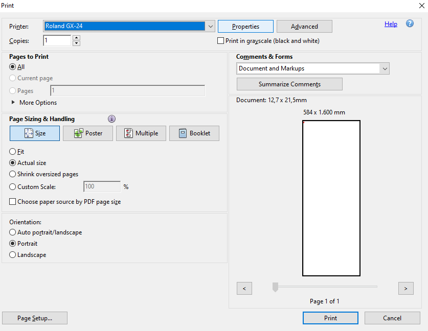 In the Print dialog, I click the Properties button at the top.
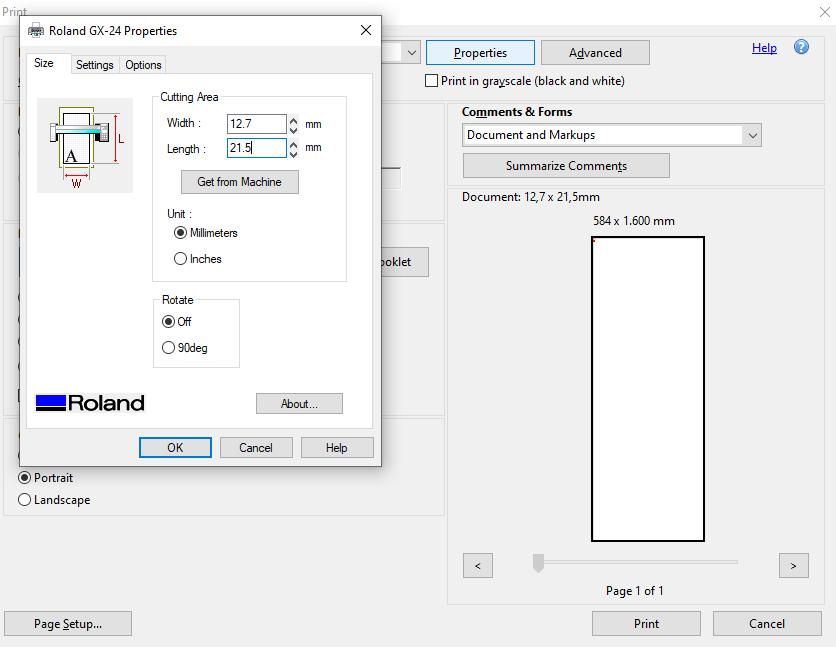 In Properties, I input the Document size which is under the Summarize Comments button. I need to enter the numbers with periods instead of commas, because this software is from the USA.
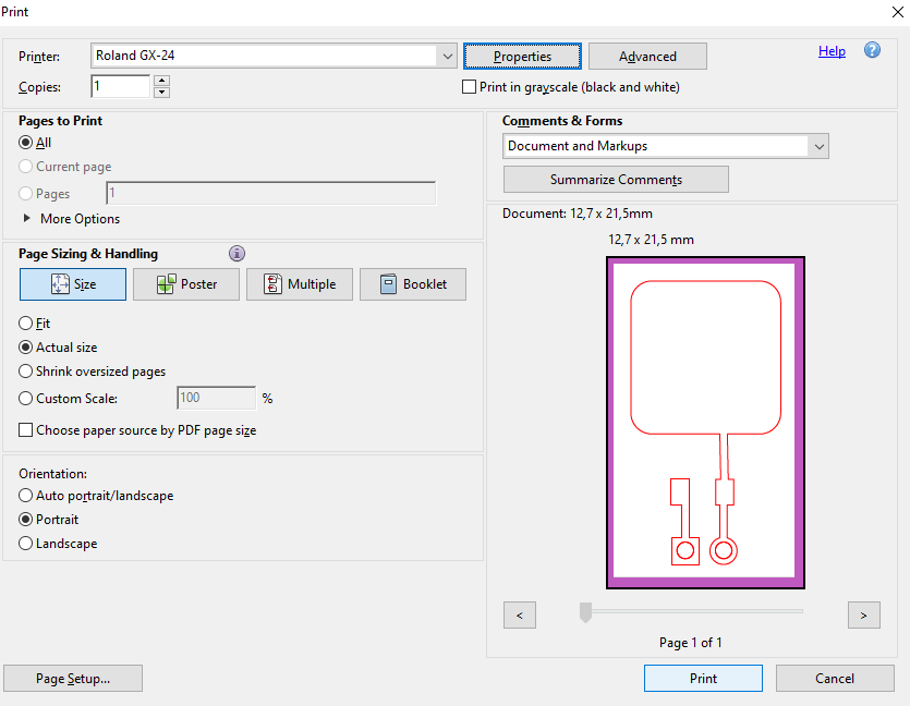 Now I can press print and the vinyl cutter makes an electronic circuit in under a minute!
Here's my first try at weeding copper sheet:
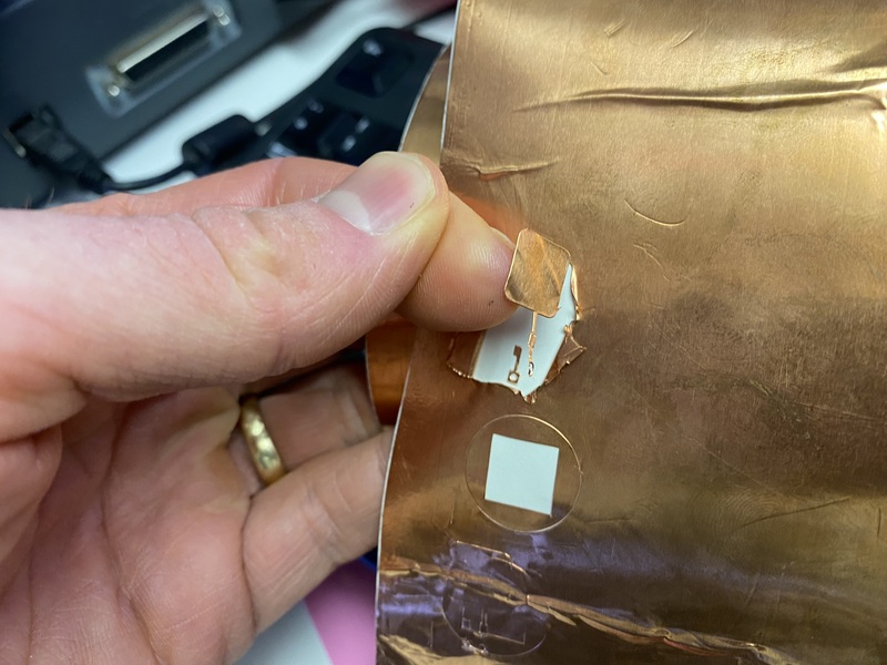 It worked, but could be better.
Neil recommended sticking everything to the final surface and then weeding. I will definitely try that next time. But this time I weeded first and then glued the copper pads to the laser cut acrylic. I forgot to add holes for pins, so I drilled them afterwards:
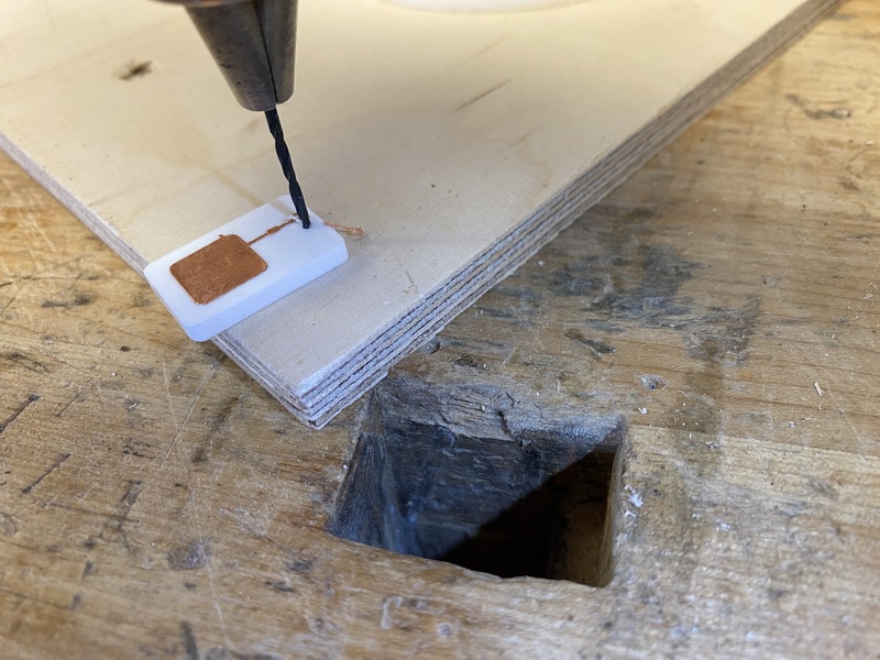 When I had my students make sensors like these, I added the holes to the laser cutting file.
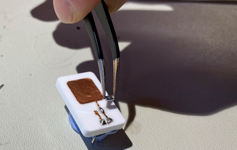 The only component on the board is a 10k resistor.
I grabbed a 10k resistor and soldered it to the pads. I'm surprised that the tiny pads survived my rough handling. Then I measured the resistance from one pin to the touch sensitive pad, to check if the solder connections were OK:
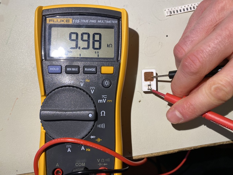
The soldering was fine, and the next step was to open a capacitive touch sensor example sketch in the Arduino IDE and connect my new sensor to a SparkFun RedBoard:
Note
I used
ffmpeg -i input_video -vcodec libx264 -crf 25 -preset medium -vf scale=-2:1080 -acodec libmp3lame -q:a 4 -ar 48000 -ac 2 output_video.mp4
Here's the Arduino sketch, which I modified a little bit (just commented out what I didn't need):
#include <CapacitiveSensor.h>

/*
 * CapitiveSense Library Demo Sketch
 * Paul Badger 2008
 * Uses a high value resistor e.g. 10M between send pin and receive pin
 * Resistor effects sensitivity, experiment with values, 50K - 50M. Larger resistor values yield larger sensor values.
 * Receive pin is the sensor pin - try different amounts of foil/metal on this pin
 */


//CapacitiveSensor   cs_4_2 = CapacitiveSensor(4,2);        // 10M resistor between pins 4 & 2, pin 2 is sensor pin, add a wire and or foil if desired
CapacitiveSensor   cs_4_6 = CapacitiveSensor(4,6);        // 10M resistor between pins 4 & 6, pin 6 is sensor pin, add a wire and or foil
//CapacitiveSensor   cs_4_8 = CapacitiveSensor(4,8);        // 10M resistor between pins 4 & 8, pin 8 is sensor pin, add a wire and or foil
int LEDpin =13;

void setup()
{
//   cs_4_2.set_CS_AutocaL_Millis(0xFFFFFFFF);     // turn off autocalibrate on channel 1 - just as an example
   Serial.begin(9600);
}

void loop()
{
    long start = millis();
  //  long total1 =  cs_4_2.capacitiveSensor(30);
    long total2 =  cs_4_6.capacitiveSensor(30);
   // long total3 =  cs_4_8.capacitiveSensor(30);

   // Serial.print(millis() - start);        // check on performance in milliseconds
  //  Serial.print("\t");                    // tab character for debug windown spacing

 //   Serial.print(total1);                  // print sensor output 1
    Serial.print("\t");
    Serial.println(total2);                  // print sensor output 2
   // Serial.print("\t");
   // Serial.println(total3);                // print sensor output 3

    delay(10);                             // arbitrary delay to limit data to serial port

 //   if (total3 > 40)
 //   {
  //    digitalWrite(LEDpin, HIGH);
  //  }
  //  else
  //  {
  //    digitalWrite(LEDpin, LOW);
  //  }
}
Design files
Download sensor vinyl cutting file
Download outline laser cutting file
Rubber stamp
For the rubber stamp engraving, I used this reference. I was able to cut through the rubber at 5% speed and 100% power with our 40W Epilog Mini 24x12 laser cutter:
The engraving test that looked cleanest to me was at 30% speed and 100% power. I then engraved the Fab Lab Ísafjörður logo with two such passes and cut out the outline:
As you can see, this makes for an awful stamp. I both forgot to mirror the logo and invert it, to make it stick out. I haven't had time to make a proper stamp yet, but the tests look promising.
Design files
Download failed rubber stamp logo
Download failed rubber stamp outline
Characterizing our vinyl cutter
We have a Roland CAMM-1 GS-24 vinyl cutting machine. It can cut with a force of up to 350 g. I've only gone up to 120 g with the copper sheets. The maximum cutting width is 584 mm and the maximum length is effectively unlimited (25 meters). It can cut up to 1 mm thick materials.
The vinyl cutter has optical sensors which it uses to measure the size of the sheet. It has a fast and powerful servomotor. It cuts really quickly, so it's a good machine to use when introducing a large group to the Fab Lab.
This vinyl cutter has an optical registration system, so you can for example print stickers, include some registration marks on the sheet, pop it into the vinyl cutter and have it cut the outlines of the stickers. I haven't tried this feature yet.
For those who want to dive deep into how computer controlled machines work, Fransisco Sanchez made a video on making machines move with mods CE. He starts with this vinyl cutting machine, which is a standard machine in the Fab Lab Inventory. I've watched part of it, it's really interesting. If you learn to speak the machine's language then you can make all sorts of new interfaces with it that don't exist today.
Characterizing our laser cutter
Our laser cutter is the 40W Epilog Mini 24x12. It's a CO2 laser with a 610 x 305 mm work area. It can cut up to 5 mm acrylic and MDF and engrave acrylic, MDF, glass and stone. I've also used it to mark metals using Laser Ink. I always open up this Instructable which Sun-Olkkonen wrote while she was an intern at Fab Lab Ísafjörður in 2018. Her guide has become quite popular.
It's important to watch the machine while it cuts, because it's always just seconds away from starting a fire if something goes wrong. And things do go wrong somtimes. And you must never laser cut any plastic material that contains chlorine, like PVC for example. When it vaporizes such a material, chlorine gas is created, which is deadly.
Kerf test
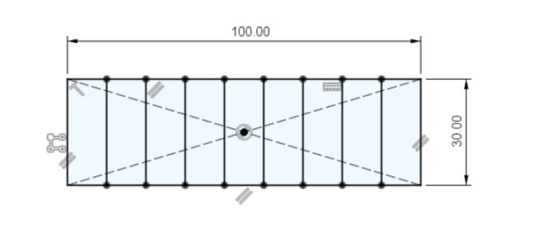
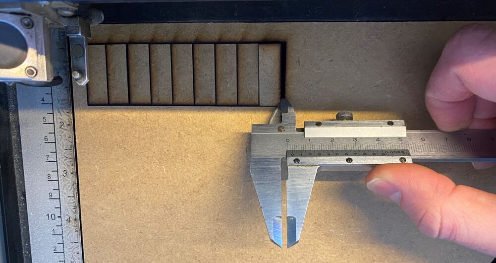
The missing width when I've laser cut these ten lines is exactly 2 mm. That means that the laser's kerf (or the diameter of the laser point) is
So when I design a press-fit joint, I need to offset all lines outward by 0.1 mm.
Design file
Raster test
I used the same raster test as I did with the rubber stamp. I set the laser power to 100% and the frequency to the maximum 5000 Hz. Then I enabled Color Mapping in the Epilog Laser settings within the Print dialog in the PDF viewer.
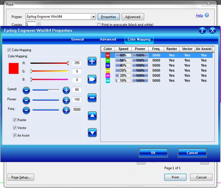 The Color mapping dialog. You press the triple arrow to save the setting.
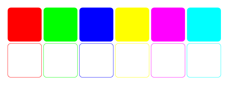 Red is 60% speed, green is 50%, blue is 40%, yellow is 30%, magenta is 20% and cyan is 10%. That goes for both rastering (top row) and cutting (bottom row).
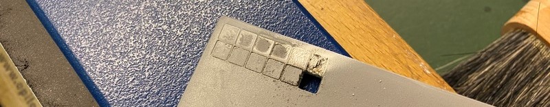
Here's how the 4 mm MDF reacted to these settings:
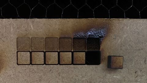 To get a clean raster, the speed must be above 30%. To cut through the material, the speed must be 10% or slower. I usually use 5% speed to make sure that the laser cuts through.