Electronics Production 
Assignment
Group assignment
- Characterize the design rules for your in-house PCB production process
- Send a PCB out to a board house
Individual assignment
- Make and test the development board that you designed to interact and communicate with an embedded microcontroller
- Extra credit: make it with another process
See more info and recording of the lecture here.
Vinyl cutting electronics
Making a vinyl cutting file in Inkscape
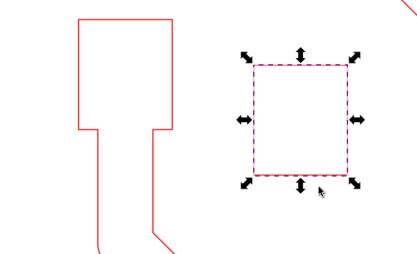
I had to go into Inkscape and do a bit of editing of the SVG that I exported out of KiCAD in Electronics Design week. The traces were only single lines, so I couldn't just set the line width to 0.02 mm and start cutting. I used a little trick; I converted the stroke to a path.
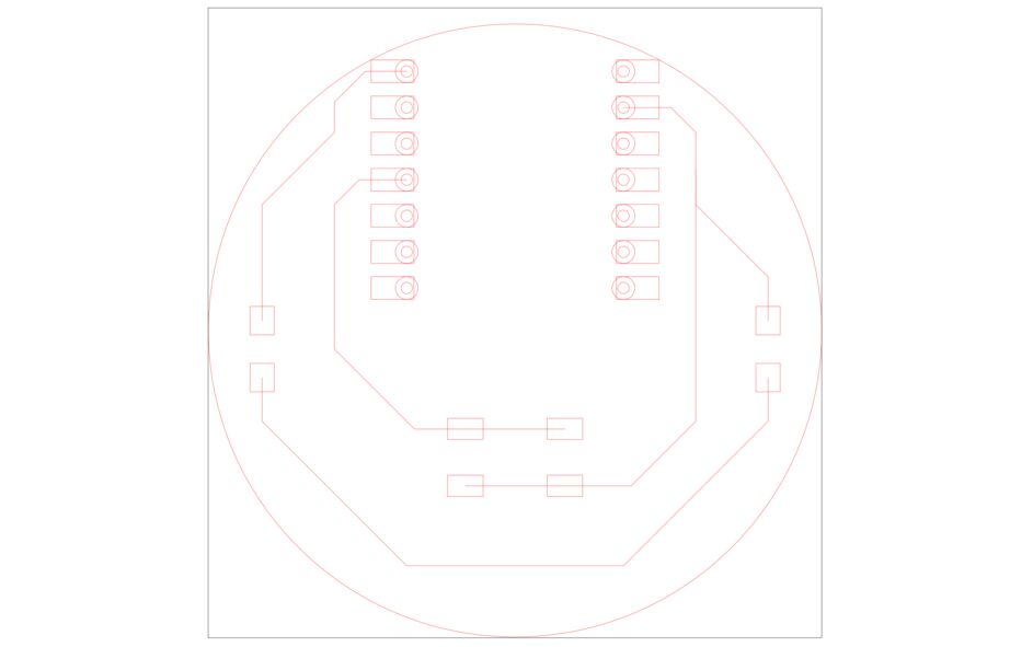 These lines won't work.
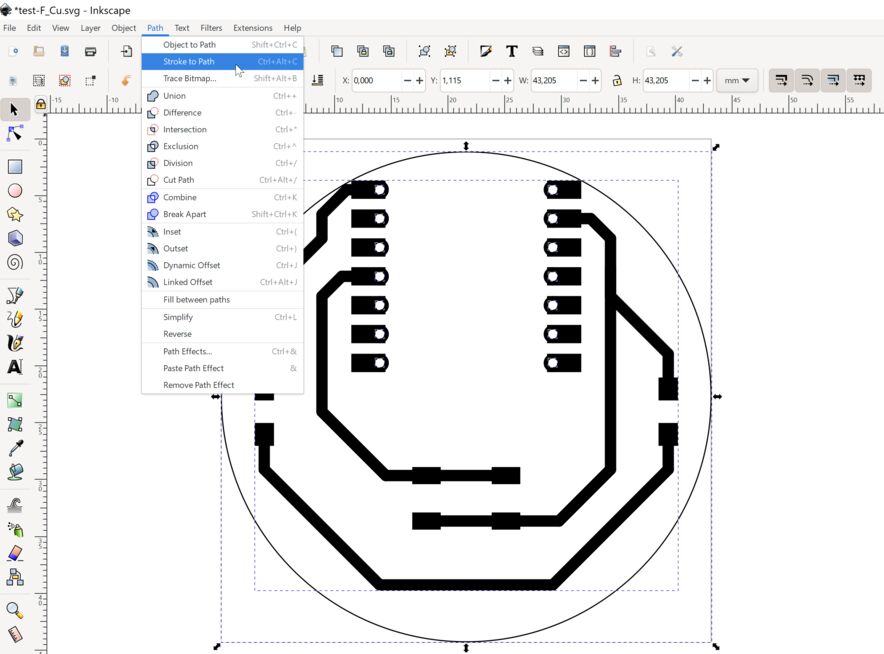 Stroke to Path.
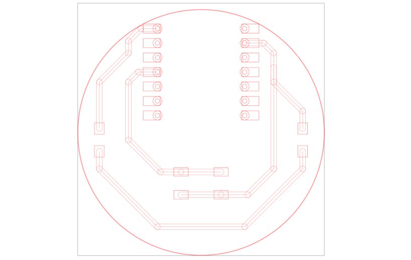 Now I have lots of lines. Too many, even. But I can work with these.
Now I had a lot of intersecting shapes, which I was able to combine using Path -> Union. After that, it was only a bit of cleaning up, since there was an extra rectangle left over on each pad.
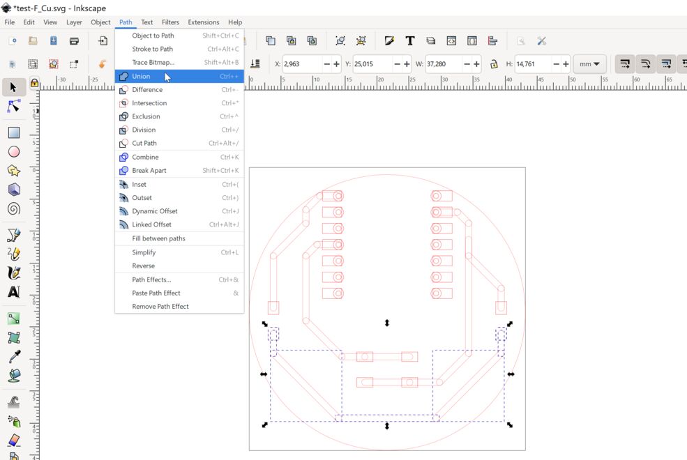 Path -> Union.
 Removing duplicate lines.
I made the lines red, set the line width to 0.02 mm and exported to PDF (File -> Save As and then select PDF as the output).
Cutting the circuit
Cutting the circuit didn't go perfectly. Some of the pads came loose when the cutter was cutting holes in them. Checking the design in Inkscape, I found that there was an extra circle on top of every hole. So each hole was cut twice. I also realized that I didn't need to solder pins onto the Xiao module, I could surface-mount it! So I deleted all the holes and cut again. This time the circuit came out perfect. I love making circuits on the vinyl cutter! It's so quick and easy.
I found a MicroPython blink program to run on the RP2040. All I had to do was to look at the pinout on the Xiao module to see which GPIO pin I had connected to the LED. That's pin 26. I substituted that into the program and pressed play. It works!
Here's the blink program in MicroPython:
from machine import Pin, Timer
led = machine.Pin(26, machine.Pin.OUT)
timer = Timer()

def blink(timer):
    led.toggle()

timer.init(freq=2.5, mode=Timer.PERIODIC, callback=blink)
I also tried programming it in C++ in the Arduino IDE. Here is my board with the button working:
And the Arduino code:
#define BUTTON_PIN 29
#define LED_PIN 26
bool status = 0;

void setup()
{
  Serial.begin(9600);
  pinMode(BUTTON_PIN, INPUT_PULLUP);
  pinMode(LED_PIN, OUTPUT);
}

void loop()
{
  status = digitalRead(BUTTON_PIN);
  Serial.println(status);
  if (status == 1) {
    digitalWrite(LED_PIN, LOW);
  } else {
    digitalWrite(LED_PIN, HIGH);
  }
  delay(100);
}
Design files
Here is the KiCAD project:
PCB milling
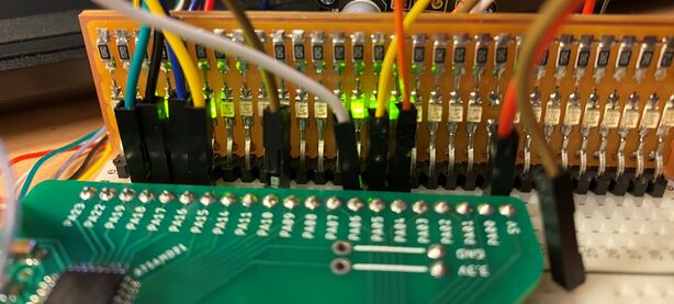
I decided to make an LED debugging board. I've wanted something like this for a while. Sometimes you just want to see if something is happening on the output pin that you've defined. Or you're not sure which pin is which. I think an LED board can help when you're figuring out if the problem is in the circuit or in the code. So I designed a board with 30 LEDs, which covers the whole length of my breadboard:
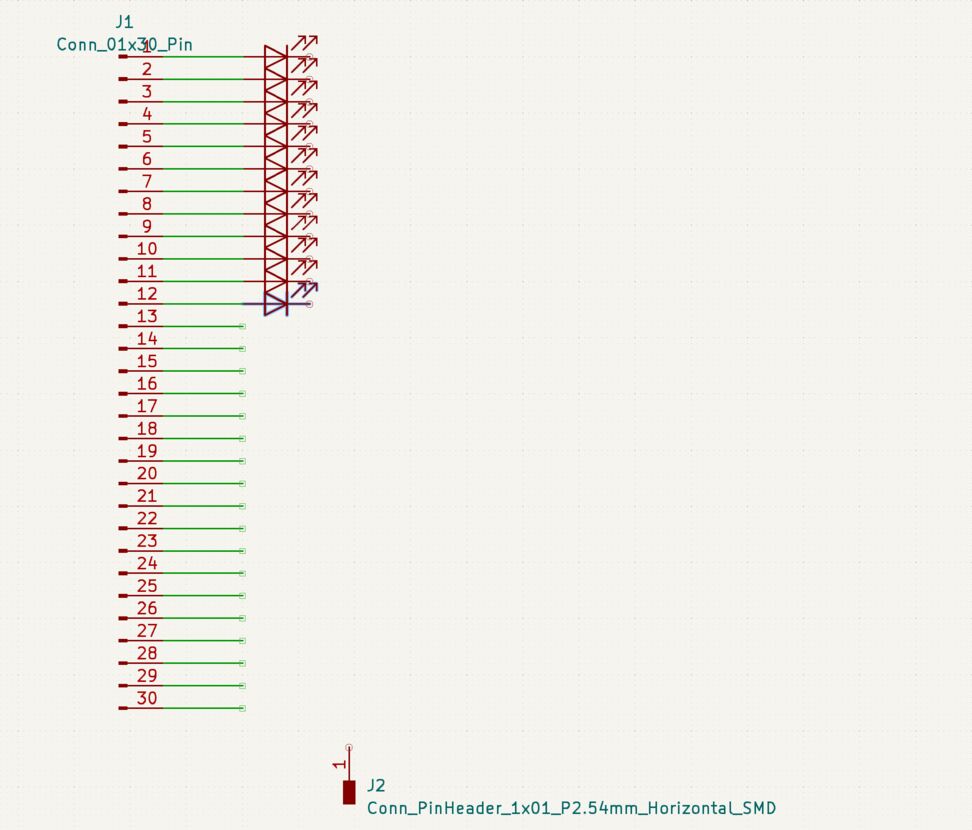 Here I'm placing a simple pattern of LEDs, each with a current limiting resistor.
Most of the work took place in the PCB layout environment. I needed to rotate every LED individually and align it and its resistor with the others.
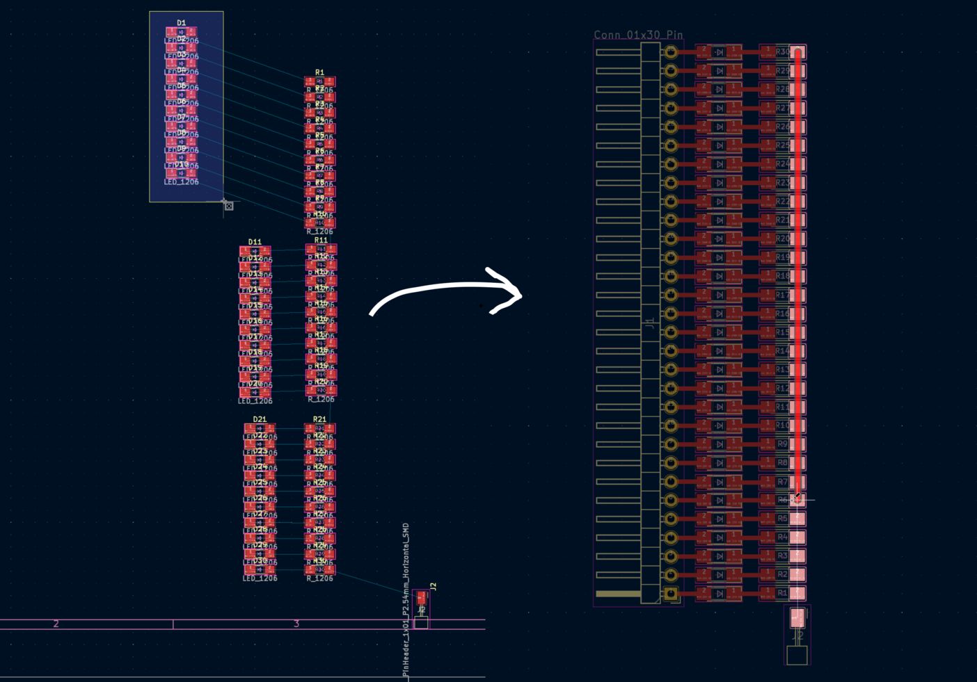 I had to do a fair bit of rotating and arranging to get all the resistors and LEDs in line.
Then I selected File -> Export SVG and opened the SVG file in Inkscape. Unlike the vinyl cutting file, which needs to be a perfect SVG, what I'm using now is a PNG. So I only need to set the colors of the board and traces right, and that's it! Export to PNG with 1000 dots per inch resolution.
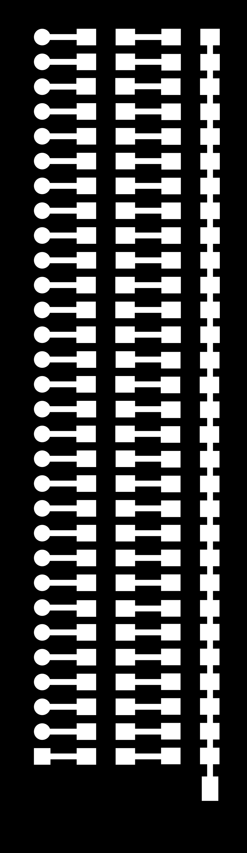
 The production files are simple PNG images. You can save these and load them into Fab Modules to make your own LED test board. The left one (traces) is milled with a 1/64" bit and the right one (interior) is milled with a 1/32" bit to cut the outline of the board.
 To mill the traces I took the milling bit out of the collet and put the 1/64 inch bit in. Initially the bit should only be poking a little bit out of the collet.
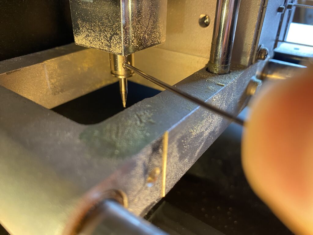
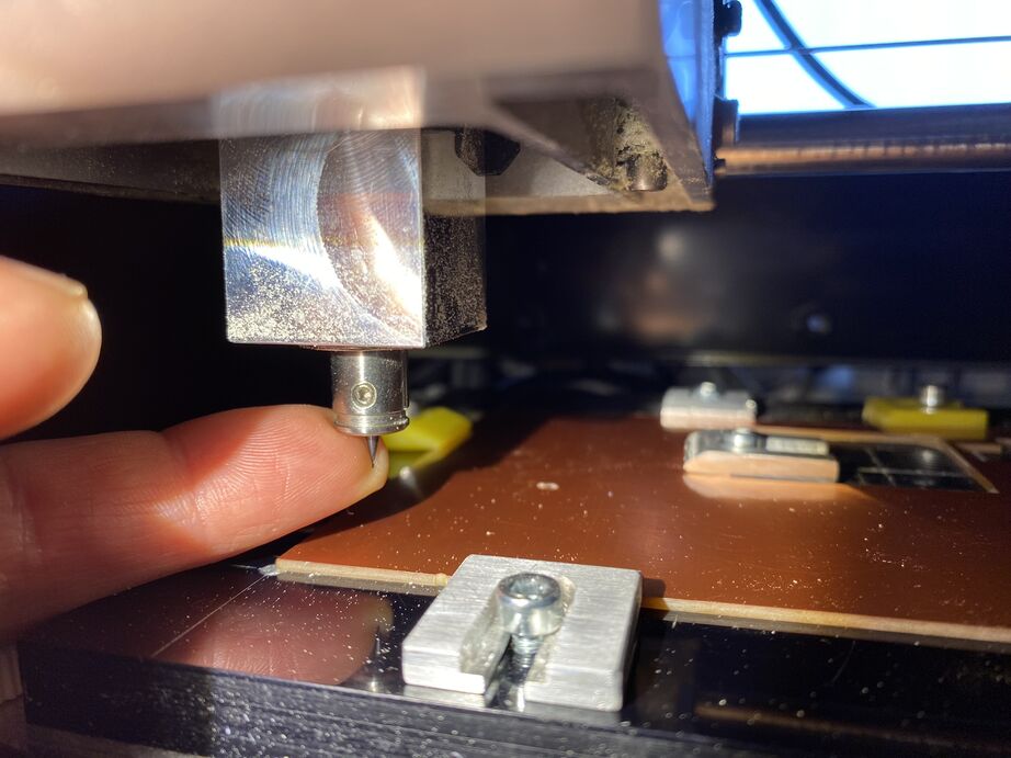 When over the PCB and the Z-axis is in zero position, I loosened the milling bit, taking care to keep it from dropping and breaking.
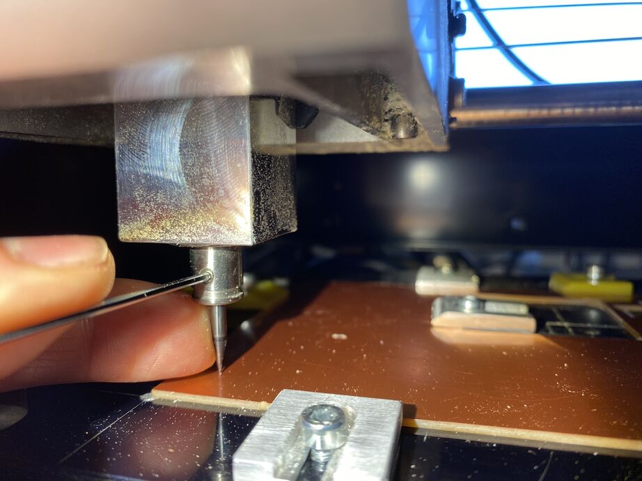 Then I lower the bit onto the PCB, thereby zeroing it. I push it gently down with one finger while I tighten the set screw, otherwise the screw can lift the bit slightly as I fasten it.
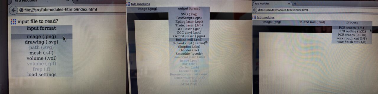 The traces PNG is loaded in Fab Modules, RML code for Roland Modela mills is selected and PCB traces is selected. We have Fab Modules running locally on an ancient Linux machine and I don't know how to take screenshots on it. Sorry.
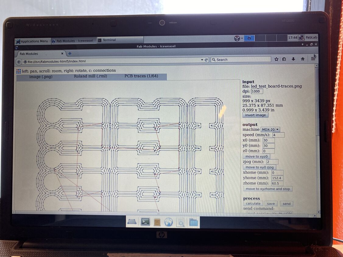 Then I select the MDX-20 milling machine, click Calculate to generate the toolpath and click Send to send the RML code to the machine.
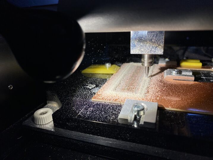
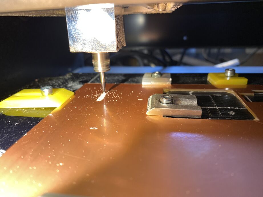 Starting to mill the traces on the Roland MDX-20 machine.
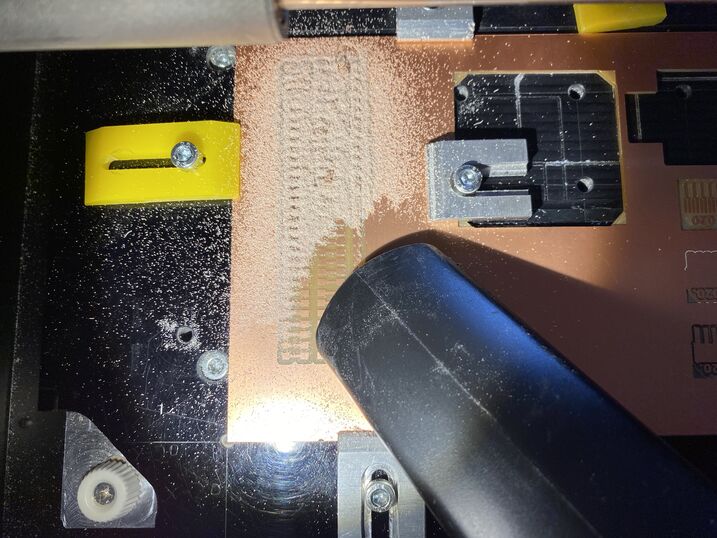 Vacuuming the dust away after milling.
Fab Modules selections for milling the PCB traces.
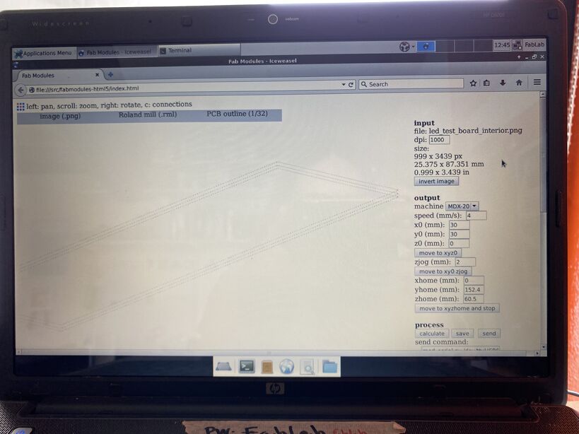 Generating the toolpath to mill the PCB outline. The interior PNG was loaded this time and PCB outline selected instead of PCB traces. Did you know you can rotate the view in 3D in Fab Modules? It's great!
 Milling the board outline with a 1/32 inch bit. I changed the bit with the same procedure as before.
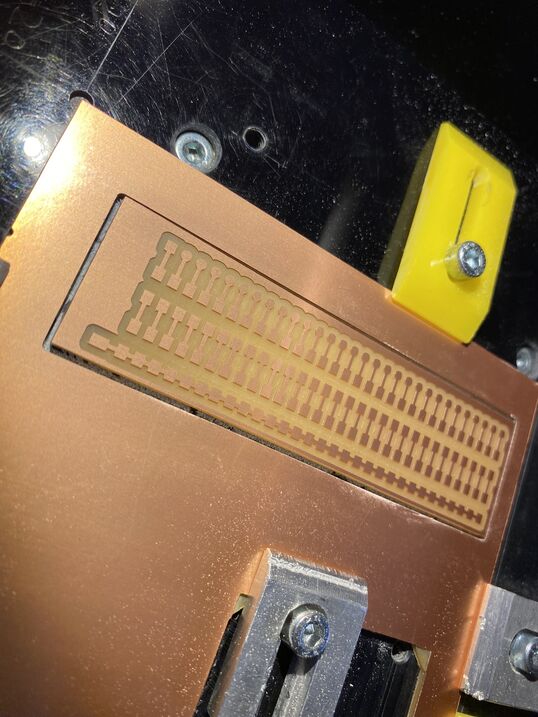 After another round of vacuuming, the board is ready for soldering!
 Soldering, then stopping to test the resistor sizing. First I tried a 1kOhm resistor, which made the LED too dim. Then I tried a 10Ohm resistor, which was just right. Then I soldered the rest of the resistors and LEDs onto the board. I enjoyed the process, but if I were to make many of these boards, I would start thinking about a Pick-and-Place machine. The LumenPNP seems nice.
LED debugging
I used the LED to troubleshoot my final project. First I made a simple program that blinks all the pins. It helped me to determine which pin on the IC relates to which pin number in the Arduino IDE, using the Arduino Nano 33 IoT board definition (because that's the only Arduino core that worked with my libraries).
Blink all the pins! I noticed gaps, where a few pins weren't broken out on the board. I could identify them by slowing the blinking down and having the SAMD21 report the pin number to the serial monitor.
Then, when the brushless motor was moving erratically, I added the LED board to the breadboard again to the breadboard to see if I was getting PWM signals on all three motor phases:
 I got a steady ENABLE signal and two PWM signals. There should also be a PWM signal on the brown wire. I had accidentally used a pin that wasn't broken out on the board for the third PWM signal. I quickly changed the pin in the code and the motor spun smoothly. See more in Final Project: Electronics Design.
Design files
Download LED test board KiCAD project
PCB milling test
1/64th inch bit
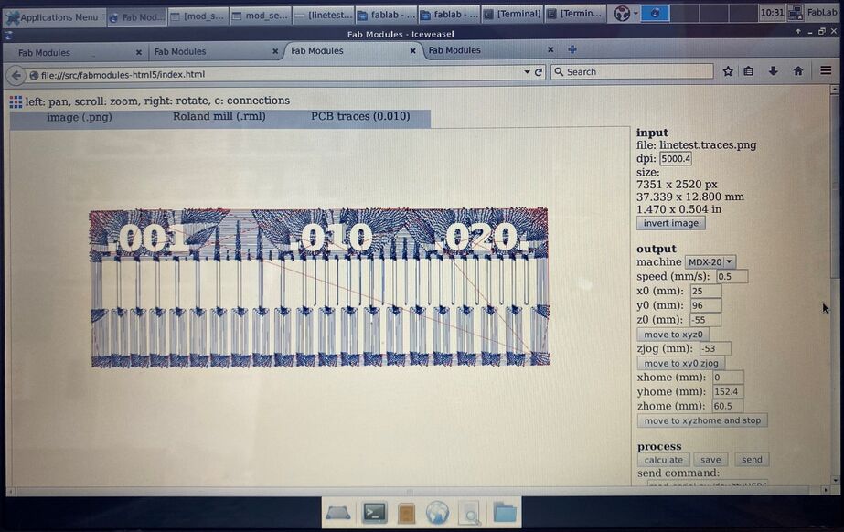
I made Neil Gershenfeld's PCB milling test using the 1/64th inch flat end mill. I used a local instance of the old Fab Modules running on a Debian Linux laptop. I used the standard speed of 4 mm/s and a cut depth of 0.1 mm. Under "number of offsets" I put -1, which means that I want to clear the board completely of copper around the traces.
 The toolpaths in Fab Modules. I wonder how Neil programmed this from scratch.
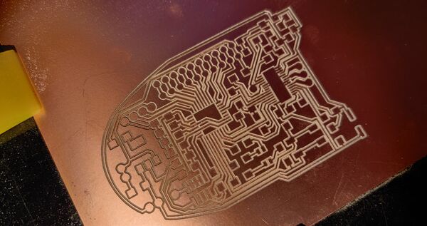
 I think these traces came out rather well The depth of cut seems to be good since the copper is completely removed. The edges are relatively smooth, so the milling bit must be in good condition. The very finest traces came loose from the board. That's good to know. It seems to be best not to make traces thinner than 0.3 mm.
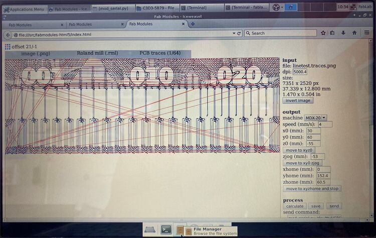
0.01 inch bit
Then I tried the super thin 0.01 inch flat end mill, and I must admit that I forgot to change the milling speed. So the first attempt was at a fast pace of 4 mm/s. The end mill broke immediately. Then I tried again at a slow speed of 0.5 mm/s and the same cut depth 0.1 mm. It also broke quite quickly. This was frustrating.
 There are more offsets, since the milling bit is thinner.
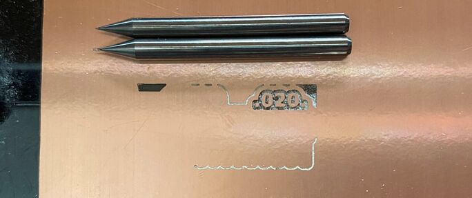 I broke two 0.01 inch milling bits trying to mill this test file.
Eventual success with fine traces
I waited until the final project to try the 0.01 inch end mill again, then at the very slow speed of 0.1 mm/s. It worked for an hour and then broke in the middle of the night. I documented my frustration in my final project video and in my final project presentation, Neil Gershenfeld mentioned that everything has to be perfect for this milling bit to work. You have to plane the wasteboard, clean the machine, everything has to be just right. And I think I also made the mistake of having it mill all the traces, instead of just around the ICs with the smallest pads.
 In the end I was able to mill the finest traces on my final project board with a V-bit. Then I cleared the whole board with a 1/64th inch flat end mill and milled the holes and outline with a 1/32 inch flat end mill.
Here is the assembled robot joint running a PID control loop:
Look at that! It works!