Multichannel data acquisition device (DAQ )
Overview
My Master's thesis project in mechanical engineering is a suspension seat for speedboats. I'm going to drop test the seat and perform sea trials with it. So I need a device that lets me make dynamic measurements to assess the seat's shock mitigating performance.
I haven't designed the device yet, but I've gathered lots of information:
Requirements
The literature recommends 24 bit data AD converters, or at least not below 16 bits, to measure acceleration on suspension seats. I've looked around for a suitable high resolution, multichannel data acquisition device (DAQ) that can also handle load cells, but they seem to cost upwards of 1300 dollars, not including the sensors. The MonoDAQ is the closest I can get to an affordable solution, but it's only 16 bits and it only has 4 differential inputs. It seems that I need to make my own data acquisition system. This will not only be lower cost, but it will be a nice educational exercise as well.
Here are my requirements:
- 7 or 8 sensors
- 24 bit resolution
- At least 1000 samples per second
- Must handle weak load cell signals
- As little analog design as possible
- Some way to synchronize the measurements
- Simple communications and data processing
Fortunately, I'm a Fab Academy graduate, and so I'm no longer intimidated by assembling a device myself. I know that accurate analog design is tricky, and so I want to make the analog path as short as possible. The usual method is to pair an instrumentation amplifier (either an IC or made of discrete op-amps) with a high-resolution analog to digital converter (ADC) and send the digital values to a microcontroller for processing and storage. I've looked at many of those, but the field is vast and I'm unsure which instrumentation amplifier goes best with which analog to digital converter.
Analog front end
AD7190
Finally, I found the Analog Devices AD7190, which is a complete analog front end for high precision measurement applications. It's an expensive IC, but a cheap data acquisition device. I can get a ready-made board with this IC, but I like to make things from scratch in order to know how everything works.
The AD7190 is a 4.8 kHz, 24 bit sigma-delta ADC with a programmable gain amplifier (PGA) with gain from 1/2 to 128! That's the widest data-rate and input signal range of any sigma-delta ADC. This means that I can connect any sensor to it, from accelerometers to temperature and pressure sensors, even to strain gauges! Strain gauges are the trickiest of all, because the signals you get are extremely weak and you usually need a chip that is dedicated to strain gauges. The problem with those is that these chips usually have a very slow data rate, up to hundreds of Hertz at most. That's not sufficient for my dynamic measurements. The AD7190 is perfect though, because I can use the same IC on all the sensors and sync all the measurements together with a clock signal (This application note points out problems with routing clock signals over long distances). And the chip has a few siblings, one of which (the AD7195) can provide an AC excitation signal for load cells, to boost the measurement precision.
Precision regulator
I've been digging into the circuit note that shows a complete weigh scale design using the AD7190 chip. The circuit note says that the AD7190 analog section must be powered from 5V. That's a little bit disappointing, since I was hoping to adjust its sensitivity by using different voltage references, based on the sensors I'm using. The suggested precision 5V regulator is the ADP3303. Is that all I need? I thought I needed a precision voltage reference like the ADR431.
Sensors
Accelerometers
Accelerometers are a whole field in themselves. Choosing the right one for my tests is quite daunting. Fortunately, I know that my thesis adviser has been using the Bosch BMA280 for acceleration measurements on speedboats with good results. This IC is a digital three-axis accelerometer with 14 bit resolution and a 500 Hz data rate. OK, I can find an IC that has similar or higher specs.
The ADXL359 from Analog Devices is a three-axis 20 bit digital accelerometer. This fits the requirement to not have to do analog design. But it's a tiny IC and I don't know how to synchronize it with the AD7910 chips.
The ADXL316, ADXL326, ADXL356 and the new ADXL358 are analog accelerometers that have the 16-20 g range that I'm looking for. They all come in tiny packages, except fo the ADXL356. It comes in a 14-lead LCC package, which I may just be able to solder by hand. I didn't know that until I was putting this text together. The right accelerometer has jumped out at me!
The only downside to an analog accelerometer is that I'll need to calibrate it myself. How do I do that? I don't have easy access to the University of Iceland's calibration shaker here in Ísafjörður. Do I measure the acceleration in free fall and at rest and calibrate the data with those two data points? Maybe that's good enough for my purposes.
Load cells
Here's a page on load cell fundamentals.
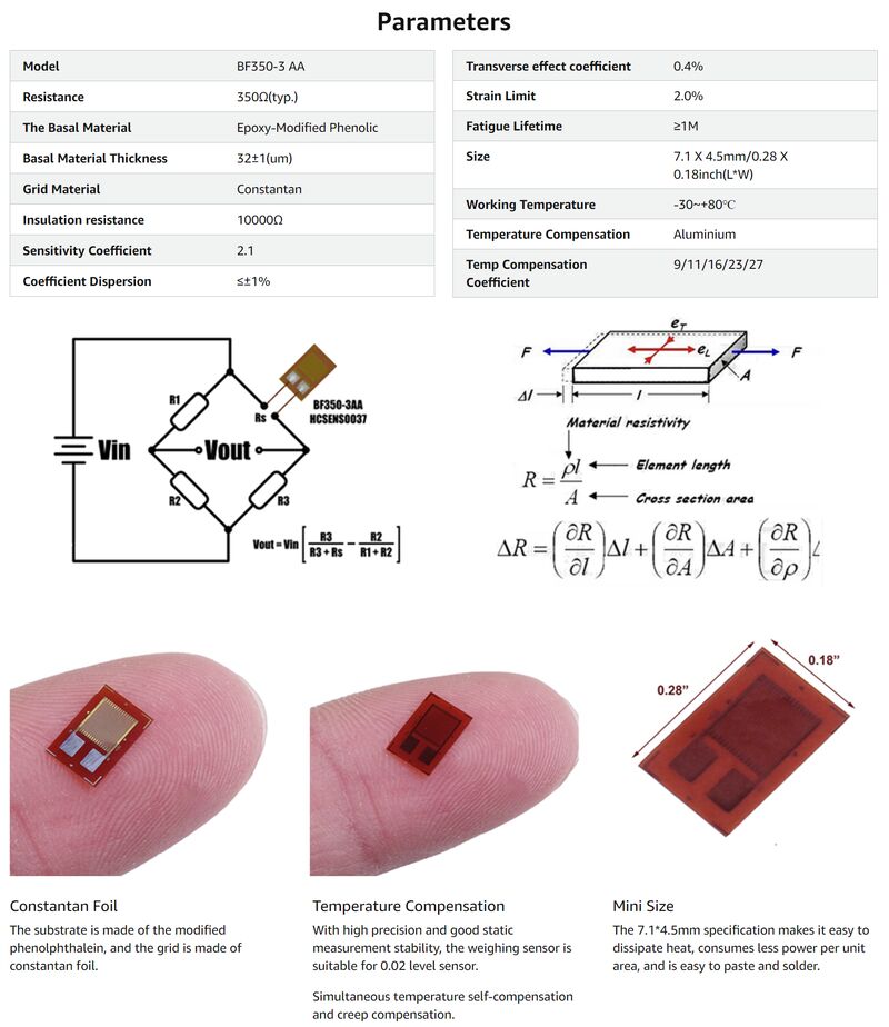
To measure the forces in the seat, I bought two 2000 kg S-type load cells. I don't know how precise they are, but this is what I could afford. They don't come with a calibration certificate. These are their specs:
- Linearity: ±0.02%F.S.
- Delaying: ±0.02%F.S.
- Repeatability: ±0.02%F.S.
- Sensitivity: 2.0mV/V
- Drifting: ±0.02%F.S
- Input impedance: 350±10Ω
- Output impedance: 350±5Ω
- Wire connecting method:
- Input: Red wire(+), Black wire(-)
- Output: Green wire(+), White wire(-)
- Yellow wire(GND)
I also have two very nice 5 kg S-type load cells from Applied Measurements. The are much higher quality, they have much more documentation and a correspondingly higher price. The 5 kg load cells have a four-wire interface.
| Rated Capacity (RC) | kgf | 0-1, 0-2, 0-5, 0-10, 0-25, 0-50 |
|---|---|---|
| Operating Modes | Tension/Compression / Tension & Compression | |
| Sensitivity (RO) | mV/V | 2.0 nominal |
| Zero Balance/Offset | ±%/Rated Output | <1.0 |
| Zero Return after 30 mins | ±%/Applied Load | <0.03 |
| Output Symmetry (tension vs. compression) | ±%/Rated Output | <0.10 |
| Non-Linearity | ±%/Rated Output | <0.03 |
| Hysteresis | % / Rated Output | <0.02 |
| Output Symmetry | ±%/Rated Output | <0.10 |
| Repeatability | ±%/Rated Output | <0.02 |
| Temperature Effect on Zero | ±%/Rated Output/˚C | <0.005 |
| Temperature Effect on Sensitivity | ±%/Applied Load/˚C | <0.005 |
| Input Resistance | Ohms | 375-420 nominal |
| Output Resistance | Ohms | 340-360 nominal |
| Insulation Resistance | Megohms | >5000 @ 50Vdc |
| Excitation Voltage | Volts AC or DC | 10 recommended (2-15 acceptable) |
| Operating Temperature Range | ˚C | -20 to +80 |
| Compensated Temperature Range | ˚C | 0 to +70 |
| Storage Temperature Range | ˚C | -20 to +80 |
| Safe Overload | % of Rated Capacity | 150 |
| Ultimate Overload | % of Rated Capacity | 200 |
| Maximum Safe Side Load | % of Rated Capacity | 30 |
| Deflection @ Rated Capacity | mm (nominal) | 1kg = 0.50, 2kg = 0.30, 5kg = 0.26, 10kg = 0.19, 25kg = 0.12, 50kg = 0.08 |
| Fundamental Resonant Frequency* | Hz | 1kg = 200, 2kg = 300, 5kg = 600, 10kg = 950, 25kg = 1900, 50kg = 3000 |
| IP Rating (Environmental Protection) | IP51 (IP67 optional) | |
| Weight (excluding cable) | grams | 25 |
| Fatigue Life | Consult Sales | |
| Cable Length (as standard) | metres | 2 |
| Cable Type | 4-core screened, PVC sheath, Ø3.5 | |
| Construction Material | Aluminium Alloy | |
| Resolution | 1 part in 250,000 (with appropriate instrumentation) |
Just for fun, I also bought a few strain gauges, in case I wanted to measure the strain in the damper body or something like that. It's also nice to have them in stock at the Fab Lab.
Along with these sensors I bought a bunch of 24 bit HX711 AD converters which are especially designed for load cells. I thought I was all set until I discovered that the data rate of the HX711 AD converter only goes up to 80 samples per second. That's not enough. But these cheap 24 bit AD converters will still be useful to have at the Fab Lab, because they are the easiest and most common way for hobbyists to interface with load cells.
Here's a CBA project that uses the maximum data rate of the HX711:
And custom multi-axis load cells made by sticking strain gauges on aluminum pieces cut with a wire EDM. Very nice. It may look fast enough when he pushes on it by hand in the video, but shock events are considerably faster than the fastest movements of the human arm.
Because I needed an alternative to the HX711, and I wanted to be able to connect all my sensors to the same type of IC, I found the AD7910 (see the Analog front end above). You can connect a load cell directly to this IC and make 4800 measurements per second at 24 bits! There is a caveat, though. When you amplify the signal, you also amplify the noise. According to this tutorial from Analog Devices, at a gain of 128 and 4.8 kHz sampling frequency you get 15.5 bits of noise-free resolution. The document assumes a load cell sensitivity of 2 mV/V, which matches my load cells. We can calculate the load cell's output at its maximum rated load like this:
The analog input range of the AD7910 with a 5V reference voltage is
in bipolar mode. I need to check what bipolar mode means. Using that assumption, the signal from a load cell only uses
of the allowable range of the ADC. What does that leave me with?
That doesn't make sense. I'm probably calculating this totally wrong.
Let's try again. It's probably better to use the number of possible values instead of the number of bits. Let's use the 15.5 bit noise-free range of the ADC to calculate how many bits I have to measure the 10 mV load cell signal:
That seems closer to the mark. I can live with 12 bits. This may not be entirely correctly calculated, but it makes me feel better. Arduino forum user jim-p says something about 12 being the probable effective number of bits (ENOB) when you connect a strain gauge to an AD7195. That seems to support my simple calculations. And as they point out in the tutorial, having a much wider input range on the ADC (15.5 bits is 46,341 values) than in the signal itself (12.5 bits is 5,932 values) means that the load cell's offset error (typically 50% of the full-scale signal) and gain error (up to 20%) definitely won't overload the ADC.
If I measure 960 samples per second instead of 4800, the useful number of bits in the ADC seems to be about 16.5 (from the graph in the tutorial). If I use 12.8% of that, I have 13.5 effective number of bits. That might be a good compromise; then the resolution is 11863 different values instead of 5932. I've just noticed that in the AD7910 datasheet, the noise performance is only given with sinc3 or sinc4 filtering enabled. There's no information about noise performance if you don't use the filters. So the filters seem important. I need to look into them.
For a 2000 kg load cell the estimated accuracy is
and if I assume the most extreme shock event will be 16 g, then the maximum mass that I can place on top of that load cell (seat plus occupant) is
For a 5 kg load cell the estimated accuracy is
For the 5 kg load cell it makes more sense to think in terms of g's, since I will be using it as a human-scale accelerometer. If I assume that the full range of the load cell represents 16 g then the mass that I attach to the load cell must be
The Wikipedia page on load cells says:
The bridge is excited with stabilized voltage (usually 10V, but can be 20V, 5V, or less for battery powered instrumentation). The difference voltage proportional to the load then appears on the signal outputs. The cell output is rated in millivolts per volt (mV/V) of the difference voltage at full rated mechanical load. So a 2.96 mV/V load cell will provide 29.6 millivolt signal at full load when excited with 10 volts. Typical sensitivity values are 1 to 3 mV/V. Typical maximum excitation voltage is around 15 volts.
OK, maybe I can supply the load cells with 15V to get a bigger output voltage. But the AD7910 handles the excitation voltage, doesn't it? And it's a 5V device. I'll look a bit further into this.
The Wikipedia page on load cells also says:
The full-bridge cells come typically in four-wire configuration. The wires to the top and bottom end of the bridge are the excitation (often labelled E+ and E−, or Ex+ and Ex−), the wires to its sides are the signal (labelled S+ and S−). Ideally, the voltage difference between S+ and S− is zero under zero load, and grows proportionally to the load cell's mechanical load.
OK, so my 5 kg S-type load cells have four wires, so they likely have a full Wheatstone bridge. Good. But the 2000 kg S-type load cells have five wires?
Position sensor
I bought this 500 mm string potentiometer to measure the seat's position. It has a 0-5kΩ resistance. In retrospect, I would probably rather have picked the 0-5V version, but I can make this work.
String pots are expensive! I suppose that you need really precise manufacturing to make the output linear. I wonder if I could make a cheap string pot with an optical sensor instead. Saving that thought for later.
Digital communication
My plan is to make a microcontroller board with lots of breakout pins and measurement boards, which can hopefully all be the same. The AD7190 uses something similar to SPI for digital communication. I know that you can connect many devices on the same SPI bus, but you do have to take care that the signals don't overlap or bump into each other. Since I don't want to dive into SPI traffic control for now, I'm going to try to find a microcontroller that can give me enough separate SPI controllers to connect each sensor to a separate SPI bus.
Option 1: The RP2040 microcontroller
I might try the RP2040. It has eight tiny programmable input-output (PIO) processors which you can program in assembly to bit-bang any communication interface you like. And of course, lots of them are freely available online, made by enthusiasts for enthusiasts. This could be the way if it turns out that the AD7190 uses a non-standard way of communicating over the bus (although I know very little about PIO programming). AD7190 datasheet says that it's SPI compatible but it uses a three-wire interface, while SPI has four wires. Some more digging is required. Anyway, I need 32 pins for eight separate SPI buses. The Xiao RP2040 only has 11 GPIO pins and the Raspberry Pi Pico has 26 GPIO pins. That's not quite enough. Even the PGA2040 only has 30 GPIO pins. And that's all the GPIO pins that the RP2040 chip has, I'm afraid. Again, I only discovered this when writing it down. Documenting things even before I start making anything seems to be an excellent way to clarify things.
Option 2: The SAMD family of microcontrollers
An alternative is the SAMD21, which I've come to like using because I can solder it by hand. The SAMD21 has six SERCOM interfaces, which you can configure to be either USART, I2C or SPI. Nice! Except I need seven SPI interfaces. The SAMD51 can give me eight SPI interfaces. It comes in a 64 or 100 pin TQFP package, so I have plenty of pins. I need 32 pins for eight separate SPI buses. I hope I can mill the board for a TQFP chip and solder it. The SAMD51 also has a high-speed SD card interface, which might come in handy for logging data.
Data processing, display and storage
I want to learn to use direct memory access (DMA) to receive a value from each sensor, store it in a specific place in memory and when all the DMA channels have flagged the transfer as complete, the main processor takes them from memory and combines all the 24 bit numbers them into one 192 bit number. It then saves that number to the SD card and sends it to the host computer over USB. I might make that number a little bigger, so that I can include timestamps. It seems that USB can carry 512 to 1024 bytes, so that should be fine.
On the computer I can make a simple Python program that receives the number, takes it apart into the individual sensor values and adds a plot point on all the graphs using Matplotlib. I can simply keep everything in RAM while it's recording and save the file afterwards.
Galvanic isolation
Keeping noise away from it is going to be your main problem.
-Anonymous user on the AD7195 thread on the Arduino forum.
It might be a good idea to galvanically isolate the DAQ device from the USB port. I could use something like this or this, based on the ADuM3160 from Analog Devices, or I could try to use the chip on my own board. Here's another one, based on the Analog Devices Adum4160/Adum3160. It even has a galvanically isolated 400 mA power output!
To make sure that I can pipe SPI signal over 1-3 m long cables, I've been wondering if I should put a microcontroller on board with the AD converter and use it to take the SPI signals and send them over CANBUS or some other differential signaling method. This note on isolated SPI communication could be useful. It mentions the LTC6820, a chip that uses a similar method; to convert SPI into a differential signal to carry over long wires. So if plain SPI doesn't work, some sort of differential signaling is needed. How about RS-485? I noticed that it's been used a lot at the Center for Bits and Atoms.
What? You mean you want to use the Cat-6 cable for the accelerometers? That's actually a bad idea. The ADXL345 is using either I2C or SPI communications and both of those are "single ended" meaning each signal is carried on one wire plus ground. That doesn't require twisted-pair cable. In fact, twisted-pair cable is bad for both of those. How far away are the acccelerometers? I2C can have problems with wires as short as 10cm and will always require hard work to get it to go more than 2m. SPI will work at high speed up to 3m and by switching to lower speeds you can get 10m with no special effort on the wiring. Just regular ribbon cable works - not twisted pair. I've got a system of 4 ADXL345's on about 8m of wire in some very harsh conditions and I have had no problems since switching the SPI clock divider to 4. They're sampling one axis each at 400Hz. One tip for the ribbon cable: put a DC wire between clock and data, such as ground. Adjacent wires will transmit high frequency interference between them. My long cables go: CS, MISO, 3.3V, MOSI, GND, CLK. I can share the design for the remote accelerometer PCBs if you want to get some made at OSHPark.
-Arduino forum post by user MorganS.
One tip for the ribbon cable: put a DC wire between clock and data, such as ground. Adjacent wires will transmit high frequency interference between them. My long cables go: CS, MISO, 3.3V, MOSI, GND, CLK. I can share the design for the remote accelerometer PCBs if you want to get some made at OSHPark.
Configuration
It would be convenient if the sensor modules would tell the main board what they are and how they need to be configured. This is inspired by the plug-and-play functionality of Modular Things. I looked around for an EEPROM memory that I could use to store the sensor's information, but it would be best if I could use a part in the Fab Lab inventory.
The ATTINY412 is cheap at $0.50 a piece, and it has a 128B EEPROM. I can hook it up to the same SPI bus as the sensor and it stores the sensor's properties in its EEPROM. When it's connected to the main board, it sends the information and then stops communicating. Now the main processor knows the sensor's properties and sends the proper gain and sampling frequency to the ADC, and the ADC starts streaming data over SPI. It would also be nice to display the sensor type on an OLED screen.
Another improvement could be to add a small battery to the main board, so that it can tell the time between data recording sessions. I find it annoying when I have to set the date and time every time I use a recording device. Maybe a supercapacitor would do the trick. It only needs to last for one or two weeks while updating the time every minute or so.
Schematic design
I found an Arduino forum thread where jim-p generously shared his schematic for a 24 bit measurement module using the AD7195. I'll base my own design on that, as well as the weigh scale example near the end of the AD7190 datasheet and a circuit note on the product page.