BLDC Modular Thing
Final version
This work was finished during the 2024 Fab Academy Instructor Bootcamp in León, Spain:
Overview
Since I've learned to control brushless DC motors so well in my final project work, I thought I might make a BLDC motor control board that you can use in your projects. BLDCs can be really tricky to use with closed loop control. Hopefully this board will simplify your development with brushless motors, because they're great!
Like Baksi the robot, this board uses the SimpleFOC Arduino library.
- Spiral 1: First I'm just going to make the board, and you can control it with any program that can send messages to a serial port.
- Spiral 2: Then I'd like to make the board work with Modular Things.
CAD
Ok, let's start with the shape of the board. It's square and quite small. It will be tricky to fit a Xiao module, the motor driver and associated components, and the connectors for the motor and the magnetic angle sensor on it. But it should be doable, I think.
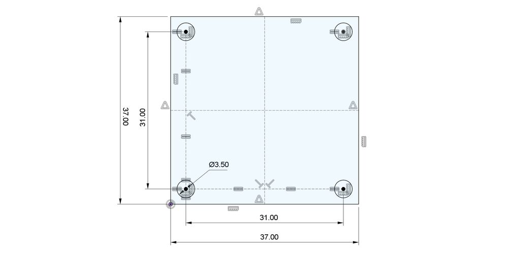 The Modular Thing footprint. Dimensions are in millimeters, taken from the Modular Things - Circuits repository. I'm using mirror constraints to position the holes.
Inspiration
I'm basing this design on the SimpleFOC Mini and the DRV8313 datasheet. I'm crossing out a few things from the SimpleFOC Mini schematic:
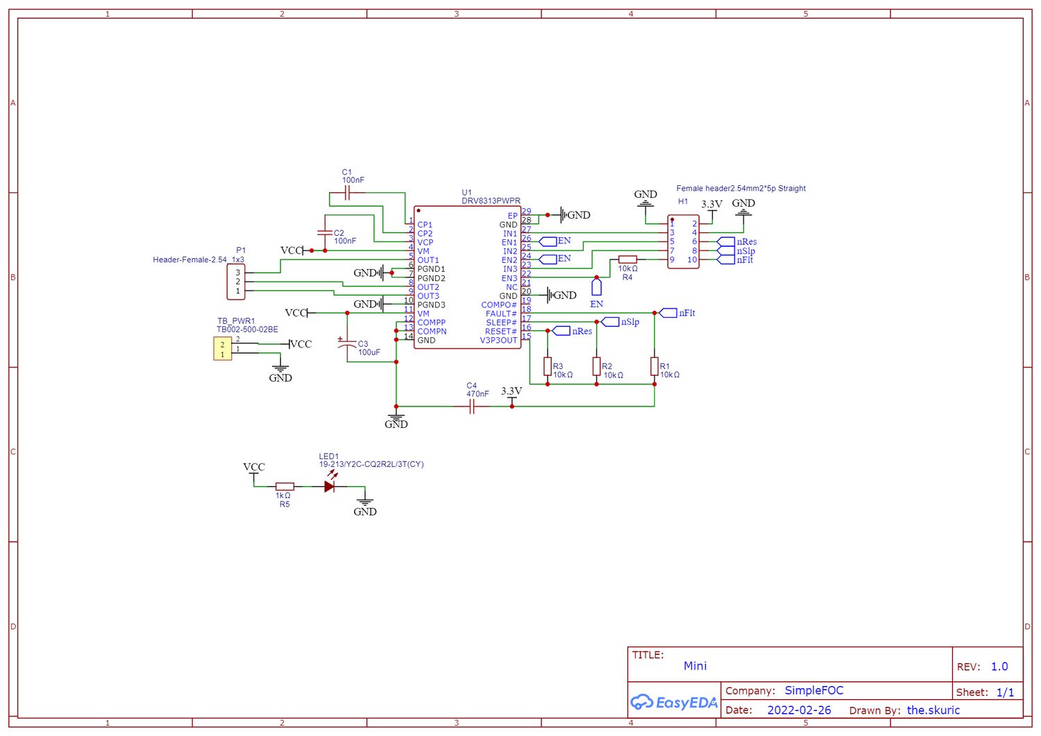 The SimpleFOC Mini schematic.
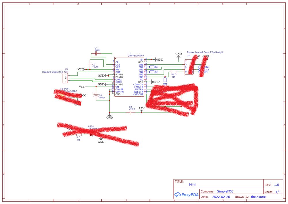 Let's get rid of all non-essential parts.
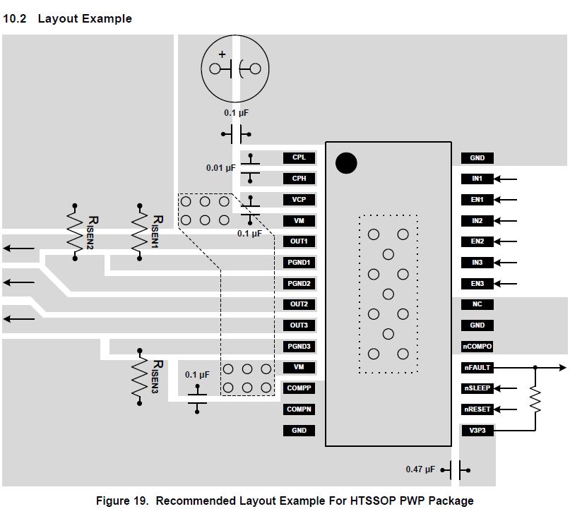
The SimpleFOC Mini board is based on the reference design in the DRV8313 datasheet:
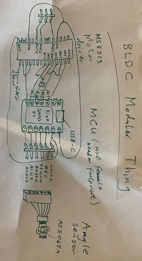
Here's an initial sketch of my board:
Actually, I was using the SimpleFOC Mini board in the breadboard version of my final project. The image above shows my (unfinished) first attempt at a schematic that simplifies the SimpleFOC Mini as much as possible. A few things are still missing; I need to pull up FAULT, SLEEP and RESET on the motor driver. I'm hoping that I can connect them all together to a digital pin that I'll set to HIGH. That would get rid of a few passive components on the board. I need to go over the SimpleFOC Mini schematic and add necessary components like the bulk capacitor.
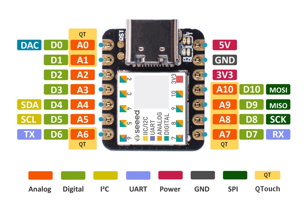
I need to reference the pin numbers on the Xiao SAMD21:
Voltage problem
I ran into a problem with my final project because the DRV8313 motor driver only works at 8V and above. So I couldn't drive it directly from the USB port as I had planned. Fortunately, I had the foresight to order a step-up/step-down voltage regulator from Pololu, in case I needed to make some last-minute voltage changes. So I put the regulator module into the base of Baksi the robot, along with a 4 port USB hub, for communication with all the joints.
Voltage fix
When browsing the SimpleFOC Community forum I came across the Mosquito BLDC driver board, which uses the MS8313 motor driver, which seems to be a knockoff of the Texas Instruments DRV8313. The MS8313 datasheet is only in Chinese, but that isn't really a problem since all its functionality is a 1:1 copy of the DRV8313.
I don't like using knockoff products because I know that developing something for the first time is at least ten times harder than copying it. However, the MS8313 driver operates between 1.8V and 36V, which is perfect for my application. I guess it doesn't take much to tempt me. Now I can get rid of the expensive step-up voltage regulator and run the BLDC motor directly from the 5V USB power supply. And the pinout is identical to DRV8313!
I may also try USB-PD at some point, like this Modular Thing. I'll probably set the voltage using jumper resistors, rather than communicating with the USB-PD IC.
Now let's try to put all this together in KiCAD.
Progress
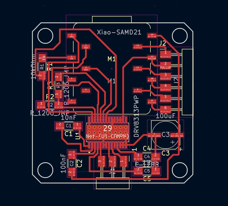
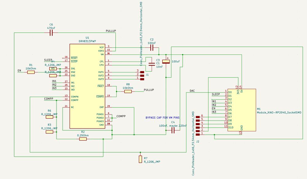
Here's the current design. Like Baksi the robot, it doesn't have current sense. I might try to add a current sense resistor or two in the next design spiral.
Current sensing!
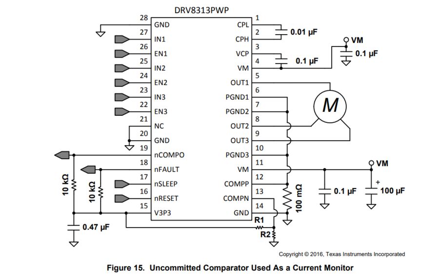
I looked more closely at the DRV8313 datasheet and discovered that it supports current limiting using a single low side resistor connected to all the motor phases. The motor driver uses a comparator to compare the measured voltage over the resistor to a reference voltage that needs to be supplied to the driver. It's very similar to how the Toshiba TB67H451FNG,EL H-bridge handles current limiting in Yuichi's Xiao_RP2040 Dual H-Bridge board. Nice!
This isn't the kind of current sensing that you can use to enable torque control, but at least I can protect the USB port from damage. That's all I want for this board.
The Xiao SAMD21 module has one DAC output pin, which I I'd like to use as a voltage reference for the comparator inside the motor driver. The SAMD DAC Application Note supports this plan:
A common use of DAC is to generate audio signals by connecting the DAC output to a speaker, or to generate a reference voltage; either for an external circuit or an internal peripheral such as the Analog Comparator.
Mirrored images in datasheet
I've run into a problem with the schematic for BLDC control with current sensing. The PCB view in KiCAD didn't make sense to me and I didn't understand why. Then I noticed that the motor driver IC is mirrored in the current sensing schematic as compared to the recommended layout schematic. This seems a bit inconsistent.
Since the recommended layout worked well in Baksi the robot, and the KiCAD footprint matches it, that is what I'm going to trust. Now I just need to mirror the current sensing schematic in order to be back on track.
 That's better.
Trip current
I will assume that the BLDC Modular Thing will be connected to a USB 3.0 or 3.1 port, which allows a 900 mA current at 5V. Let's use an upper limit of 0.8 A, to be safe.
The motor driver has a comparator that can cut the power if the current goes over a certain threshold. Now to figure out what that threshold should be:
If I use the 0.25 Ω current resistor that we have at the lab, then I can calculate the necessary voltage on the motor driver's COMPN pin according to the DRV8313 datasheet:
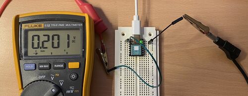
The operating voltage of the SAMD21 chip in the Xiao module is supposed to be 3.3 V. I measured it to be 3.31 V. Then I can find the value that I put into the DAC with:
I used the Xiao SAMD21 getting started guide to learn how to use the DAC. Then I modified the code to output a constant voltage level from pin A0:
#define DAC_PIN A0

void setup() {
  analogWriteResolution(10); // Set analog out resolution to max, 10-bits
  analogReadResolution(12); // Set analog input resolution to max, 12-bits

  Serial.begin(9600);
}

void loop() {
  // The measured USB supply voltage is 5.188 V and the IC operating voltage is 3.310 V.
  // 0.2V/3.31V * 1024 (or maybe 1023) = 61.8
  // OK, so to get the right reference voltage out of the DAC, measure the 3.3V Xiao pin and put into the formula above
  analogWrite(DAC_PIN, 62);

  float voltage = analogRead(A1) * 3.3 / 4096.0;
  Serial.println(voltage); // Print the voltage.
  delay(100); // Delay 1ms
}
 I can use the DAC instead of the voltage divider in the example circuit. That simplifies the PCB layout.
BOM
You need to order three things from three different places to make the BLDC Modular Thing:
- One MS8313 BLDC motor driver
- One GM2804 Gimbal Motor w/Encoder
- One Xiao SAMD21 from e.g. Seeed, Digikey or Amazon, if you don't already have one at your lab
You also need to have a Dupont connector kit at your lab (see bottom of this page).
Note
The 470 nF capacitor is recommended in the DRV8313 datasheet, but it's not in the Fab Lab inventory. Fortunately, it's only there to filter out noise in the little 3.3V regulator inside the motor driver. So you can safely use the next capacitor size above it, which is 1 uF. We'll replace the 470 nF capacitor in the next update of the design files.
| Part | Count |
|---|---|
| GM2804 Gimbal Motor w/Encoder | 1 |
| Xiao SAMD21 module | 1 |
| MS8313 motor driver | 1 |
| 100 uF bulk capacitor with 6.3 mm diameter | 1 |
| 470 nF capacitor | 1 |
| 100 nF capacitor | 2 |
| 10 nF capacitor | 1 |
| 10 kOhm resistor | 2 |
| 0.250 Ohm size 2010 resistor | 1 |
| 0 Ohm jumper resistor | 5 |
| 6 pin horizontal SMD pin header | 1 |
| 3 pin horizontal SMD pin header | 1 |
Design
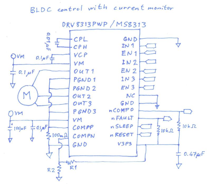
The board uses a Xiao SAMD21 to receive angle readings from a magnetic sensor via SPI and send PWM and a few other signals to the motor driver. The schematic is based on the following example in the DRV8313 datasheet:

The motor driver has a comparator that measures the current going through the 0.250 Ohm resistor (R2 on the schematic below). If the current goes over a threshold, the motor driver shuts off.
To adjust the current threshold, you need to supply a constant voltage to the COMPN pin on the motor driver. In the example above, that's done with a voltage divider (resistors R1 and R2 in the example schematic above). We're using the DAC on the SAMD21 to supply that voltage instead.
Note that the MS8313 motor driver that we're using is a clone of the Texas Instruments DRV8313. The MS8313 datasheet is only available in Chinese, but that driver is functionally identical to the DRV8313, so we can use the DRV8313 datasheet instead. Why are we using a clone? Because the original DRV8313 only starts operating at 8V. So to use that we need to add a step-up regulator (This one has been used successfully). The MS8313 can operate at 5V, so we can power the motor directly from USB.
Here's the pinout of the Xiao SAMD21:
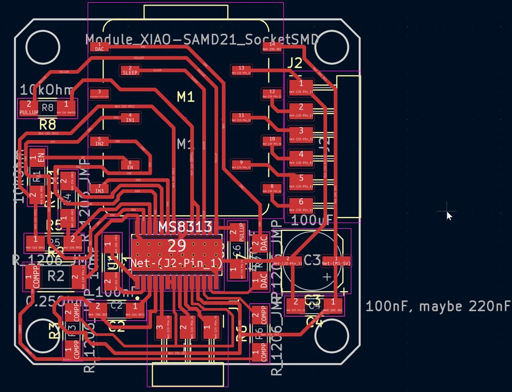
On the PCB below, all the motor driver connections are on the left side of the Xiao and all the SPI pins are on the right side. We're using socket connectors so that we can route the wires around the pads.
Here are more details about the development of this Thing.
Programming
Arduino code
The Arduino code is mostly based on SimpleFOC examples, with DAC and a SLEEP pin added.
-
Get the SimpleFOC library for the Arduino IDE.
Add the line
to the top of the Arduino/libraries/SimpleFOC/src/communications/StepDirListener.h file as described in this SimpleFOC Community post.
-
Get OSAP for the Arduino IDE.
Magnetic angle sensor
The AS5048 magnetic angle sensor has 14 bits of resolution. TThe SPI chip select pin on the AS5048 is connected to pin 7 on the Xiao, so the sensor is defined like this:
Be careful with the SPI wires for the sensors. They should be like in the image at the top of this page. When the wires overlap, the signal sometimes gets messed up and the angle stops updating in the serial terminal. It took a little while to debug this mysterious problem. Plugging the board into a breadboard also messes with the SPI signal integrity.
This is working code that reads the magnetic angle sensor and outputs the angle in radians to the serial monitor / serial plotter:
#include <SimpleFOC.h>

// MagneticSensorSPI(chip_select_pin, bit_resolution)
MagneticSensorSPI sensor = MagneticSensorSPI(7, 14);

void setup() {
  // monitoring port
  Serial.begin(115200);

  // initialise magnetic sensor hardware
  sensor.init();

  Serial.println("Sensor ready");
  _delay(1000);
}

void loop() {
  // iterative function updating the sensor internal variables
  // this function reads the sensor hardware and
  // has to be called before getAngle
  sensor.update();
  // display the angle and the angular velocity to the terminal
  Serial.println(sensor.getAngle());
}
Motor driver
The motor driver is connected to the Xiao like this:
IN1 on the motor driver connects to pin 3 on the Xiao
IN2 on the motor driver connects to pin 4 on the Xiao
IN3 on the motor driver connects to pin 6 on the Xiao
EN on the motor driver connects to pin 5 on the Xiao (enable)
So the BLDC motor is defined in the Arduino code like this:
BLDCMotor motor = BLDCMotor(7); // (This BLDC motor has seven pole pairs)
BLDCDriver3PWM driver = BLDCDriver3PWM(3, 4, 6, 5);
Trip current
We assume that the BLDC Modular Thing will be connected to a USB 3.0 or 3.1 port, which allows a 900 mA current at 5V. Let's use an upper limit of 0.8 A, to be safe.
The motor driver has a comparator that can cut the power if the current goes over a certain threshold. Now to figure out what that threshold should be:
If we use the 0.25 Ω current resistor that we have at the lab, then we can calculate the necessary voltage on the motor driver's COMPN pin according to the DRV8313 datasheet:
The operating voltage of the SAMD21 chip in the Xiao module is supposed to be 3.3 V. We measured it to be 3.31 V. Then we can find a value between 0 and 1023 to put into the DAC:
We used the Xiao SAMD21 getting started guide to learn how to use the DAC. Here's the code.
That's all you need to send a rock solid voltage of 0.2V to the COMPN pin on the motor driver.
SLEEP pin
Inside the void setup() loop, we set the SLEEP pin on the motor driver to HIGH to wake it up:
The rest of the code is built from examples in the SimpleFOC library.
Setting up the motor (contains info on zeroing)
JavaScript code
Jake and Quentin explained the Javascript needed to make a new Modular Thing in a video call. Jake has recently updated Modular Things to make it easier to make new modules.