Electronics Design
Assignment
Group project
- Use the test equipment in your lab to observe the operation of a microcontroller circuit board
Individual project
- Use an EDA tool to design a development board to interact and communicate with an embedded microcontroller
- Extra credit: try another design workflow
- Extra credit: design a case for it
- Extra credit: simulate its operation
See more info and recording of the lecture here.
Designing a simple board in KiCAD 

Here's a video where I describe what I did in Electronics Design week to Neil Gershenfeld during random review.
A few months ago I went through a short KiCAD tutorial, to get to know the program a little bit. But I got a lot more out of designing a little PCB with an LED and a button and making it on the vinyl cutter this week. Designing something without making it doesn't get me excited to do more stuff. After making the little circuit, I really want to make more. Let's get into it.
The fab library
I cloned the Fab Lab parts library for KiCAD from the Gitlab repository. It's maintained by Krisjanis Rijnieks in Finland. To use the library, I needed to upgrade to KiCAD 7.
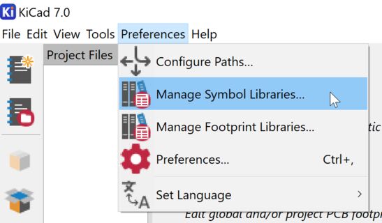
I started by going into Preferences and Manage Symbol Libraries. There I clicked the + symbol to import a new library and navigated to the location of the fab library, which is called fab.kicad_sym. Then I went into Preferences and Manage Footprint Libraries and did the same, but that file is called fab.pretty.
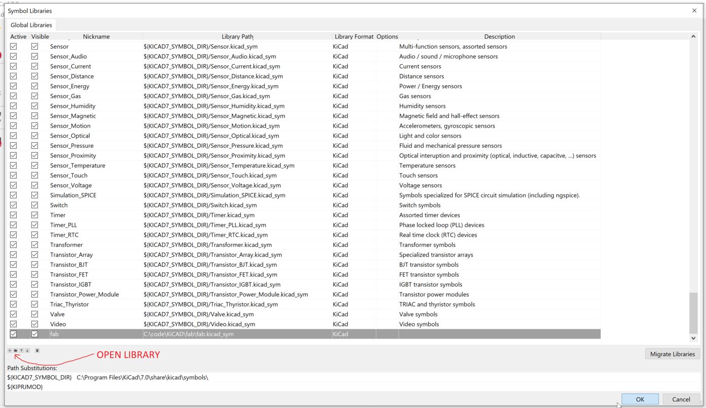 KiCAD has many parts in its libraries, but the fab library has been the most useful by far.
The schematic
Having imported all the components in the Fab Lab Inventory, I could get started with my design. I created a new design in a new folder. In the Schematic editor I pressed A on the keyboard to add components, and added a 1206 diode, a 1206 resistor to go with it, the Xiao RP2040 module and a pushbutton. I also added a power symbol and a ground symbol. Then I used the wire tool on the right side of the interface to connect the components together in a way that made sense to me.
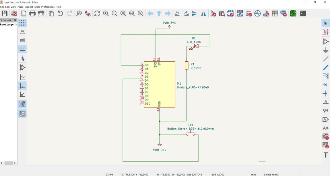 My first schematic.
Routing the PCB
Next, I opened the PCB Editor. I placed the components there all at once. They were connected by thin lines called a rat's nest, but the routing of the physical traces requires a second step. I moved the parts into a pleasing arrangement and then connected them together with the wire tool in the toolbar on the right.
 After selecting Update PCB from Schematic, I got the parts all in a bundle.
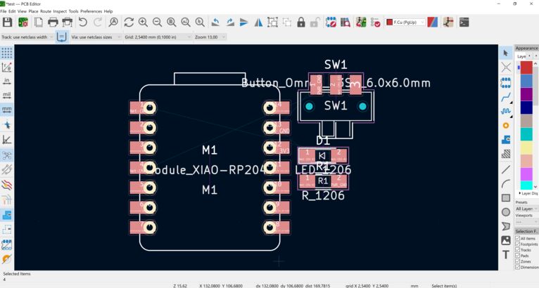
Then I realized that I probably had the wrong button, so I swapped it out. Then I arranged the parts in a pleasing way routed traces between them by pressing X on the keyboard.
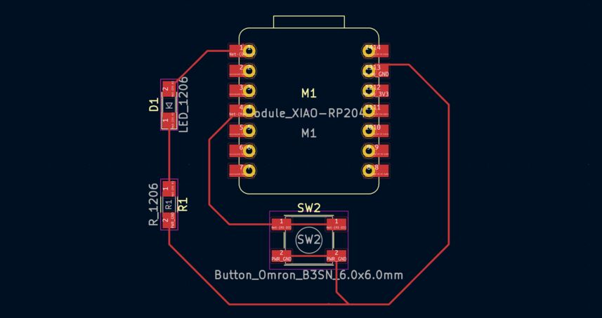 Arranged and routed.
3D Viewer
Then I tried the 3D Viewer (View -> 3D Viewer) and got a warning that I needed to define a board outline.
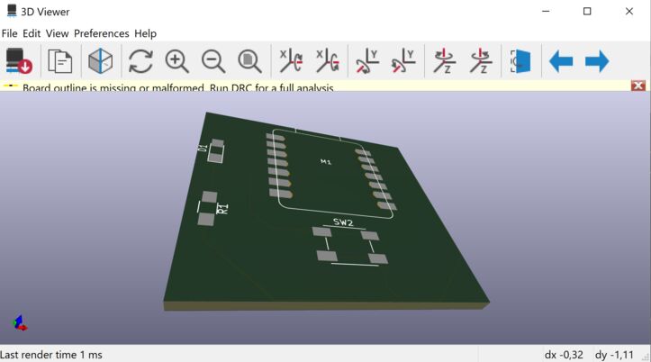 Board outline missing.
So I added a board outline to Edge Cuts. A day or two earlier, my elder son Ernir said that he wanted to make an electric thing in the shape of a circle, and close it off on all sides except one, so that we could connect it to another circle. So I made the outline a circle.
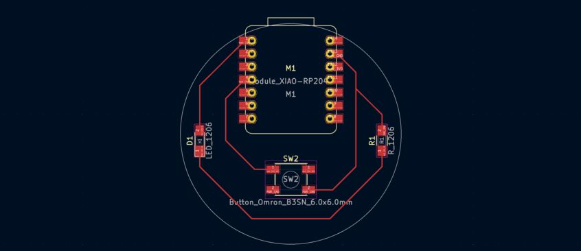 Circular board outline.
I moved the components around some more until I was happy. Then I pressed Alt+3 on the keyboard to get a 3D preview. That was underwhelming, since none of the components I used have a 3D model associated with them. I wanted at least to have the Xiao module, so that I could design an enclosure around its USB connector (if I had the time). I found the model on the SeeedStudio web site. It includes a Fusion 360 design file, but I only need the STEP file. I put the STEP file into the fab.3dshapes folder in the fab library and used this tutorial to connect it to the KiCAD footprint. Now we're talking!
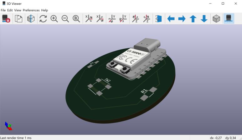 I can see the 3D model being useful when designing enclosures.
A few fixes
I exported the design as an SVG and opened it in Inkscape. It wasn't until I saw it there that I realized that the traces were too thin to cut on the vinyl cutter.
I needed to go back into the PCB Editor and use a quick and dirty way to change the track width. I selected one part of each trace, then pressed U to select the whole trace and then pressed E to open the trace properties. There I could change the trace width from 0.25 mm to 1 mm.
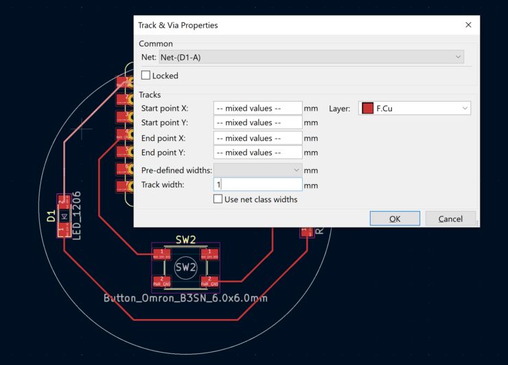 That's better.
Next time I'll set the track width from the start in the proper way using Netclasses in File -> Board Setup. That's much more convenient, since every new trace will have the width that I've defined.
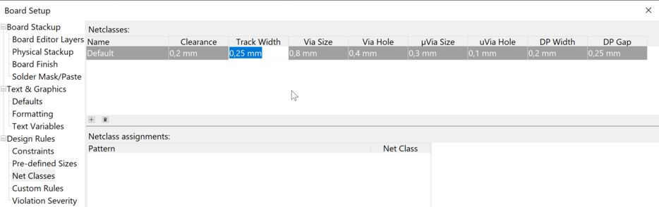 This is how you set the trace width properly for the whole board.
Now I have a completed design in the PCB editor, ready to export to Inkscape:
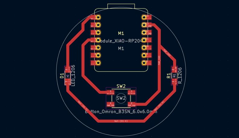 Xiao RP2040 LED board with a button.
Design files
Here are the KiCAD files for this project, including the PDF file that is ready for cutting:
Selecting a resistor for the LED
Now I needed to find the right resistor to use with the blue LED. I found a very useful tutorial from Digikey, which is where I got my parts from.
Diodes are a one-way valve for electrons. Electrons can go one way, but not the other. When diodes let current through, they have almost no resistance, and that's great. Then someone discovered that diodes can emit light. Now LEDs are everywhere and they have one caveat: You can't just connect one to a power source and have it work. Because it's such a good conductor, it will let more current through that it can handle. It will burn up, or even blow up! So we need a helper component. Every LED needs a current limiting resistor in order to survive. So, how do we select the right resistor for our blue LED?
Let's use Ohm's Law:
 Ohm's Law pyramid. Coincidentally, VIR means 'wire' in Icelandic.
It's fun to be able to make graphics like these in Inkscape and render them easily on a web page. Ok, I need to know the
- Source voltage: 3.3 V
- LED forward voltage: 3.2 V (max 3.5 V)
- LED's recommended operating current: 30 mA
But there's a catch: After reading the datasheet, I know that RP2040 can only supply 16 mA from each GPIO pin. So that's the number I'll use.
The voltage drop across the resistor needs to be
Now let's use the pyramid to get an expression for the resistor:
I have the resistance! But there's one more step: I need to make sure that the resistor can take the heat. I'll use the power formula to see the power dissipated by the resistor:
That's insignificant.
At the Fab Lab I have 4.99Ω and 10Ω resistors. Let's check the current through the LED:
4.99Ω:
10Ω:
OK, I'll use the 10Ω resistor.
Using an oscilloscope
I programmed a Raspberry Pi Pico to output stepper motor control signals. This is the same MicroPython code as I used in Embedded Programming week. It's a very simple way of creating signals for a 28BYJ-48 stepper motor.
from machine import Pin
from time import sleep

IN1 = Pin(2,Pin.OUT)
IN2 = Pin(3,Pin.OUT)
IN3 = Pin(4,Pin.OUT)
IN4 = Pin(5,Pin.OUT)

pins = [IN1, IN2, IN3, IN4]

sequence = [[1,0,0,0],[0,1,0,0],[0,0,1,0],[0,0,0,1]]

while True:
    for step in sequence:
        for i in range(len(pins)):
            pins[i].value(step[i])
            sleep(1)
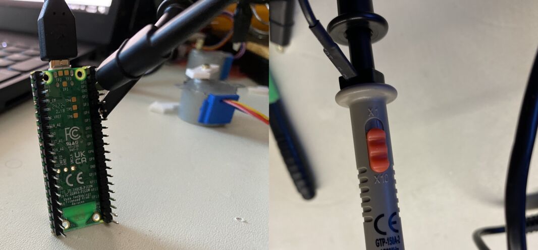
I set the probe to 10X sensitivity:
And here's what I got on the oscilloscope:
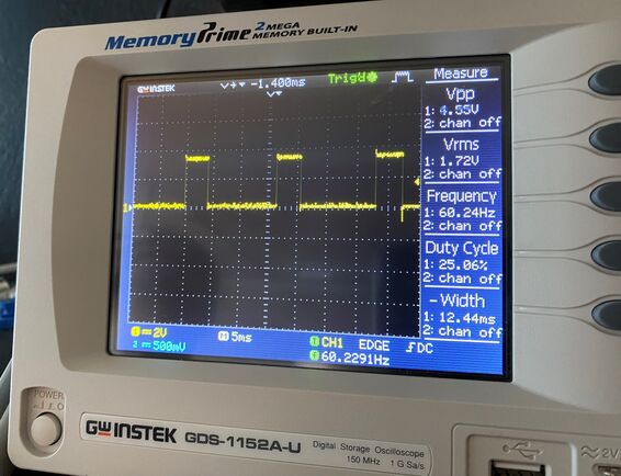 A clear step signal, at just over 60Hz. Time is on the X-axis and voltage is on the Y-axis. Then when the oscilloscope starts receiving a signal I press Auto adjust, and the scope detects how the signal looks and adjusts the time scale so the signal is steady on the screen.
I used the portable digital oscilloscope to troubleshoot my Output Devices board:
I found erratic signals coming from one of the H-bridges, which caused my brushless motor to move erratically. More info is here.
Using a multimeter
In Computer-Controlled Cutting week, I measured a resistor with a multimeter:
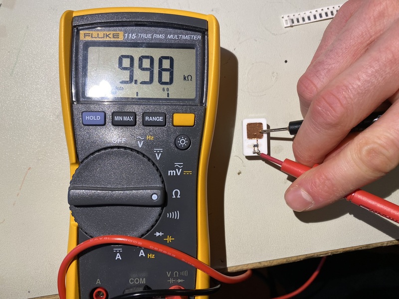 Here the circuit needs to be powered off. The resistor says 1002, and it indeed measures as 10kOhm.
In Output Devices week, I measured the voltage that an OLED gets from the power supply:
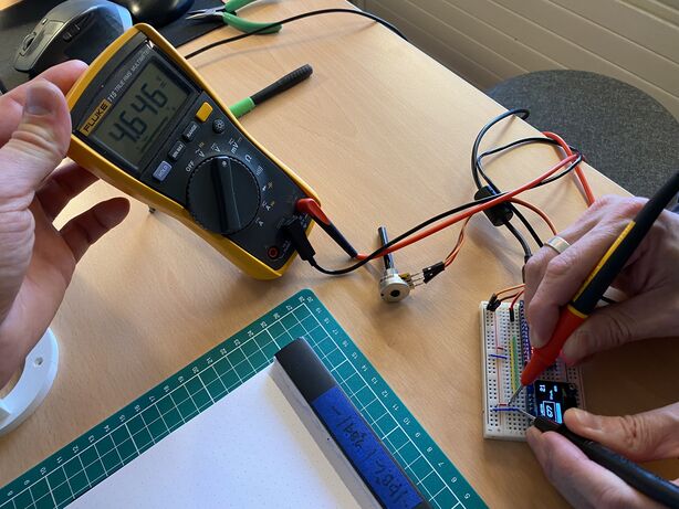 Here the circuit needs to be powered on. The OLED gets roughly 5V, as it shuould be. The OLED can operate on 3.3V-5V voltage.
I also measured the current that the OLED draws:
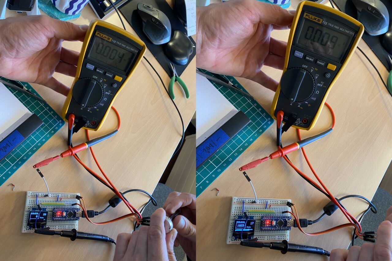 Here I need to break the circuit and put the current meter into the circuit, so that the current flows through it. Inside the current meter is a resistor with a very small, known resistance. The voltage drop over the resistor is measured and from that, the device calculates the current. On the right a bigger part of the screen is turned on, and it shows in the current measurement.