Computer-Controlled Machining 
Assignment
Group assignment
- Do your lab's safety training
- Test runout, alignment, fixturing, speeds, feeds, materials, and toolpaths for your machine
Individual assignment
- Make (design+mill+assemble) something big (~meter-scale)
- Extra credit: don't use fasteners or glue
- Extra credit: include curved surfaces
See more info and recording of the lecture here.
Design
I designed an extended table with a shelf for our coffee corner. I wondered how I could make the shelf supports look good:
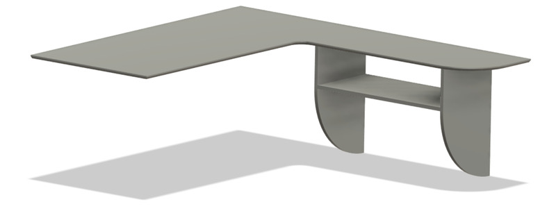
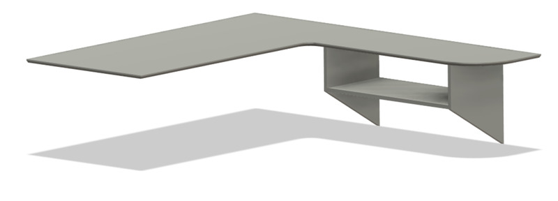
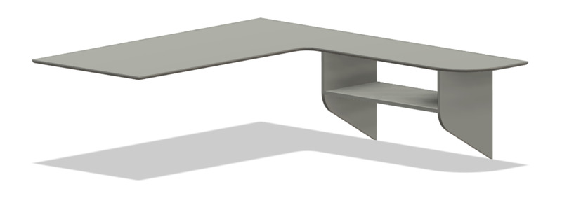
I ended up picking version 3.
Here's an example of how convenient parametric design can be:
And here's the whole design process. First I create the parts and adjust their sizes, then I model the press-fit dogbone joints and finally I move the parts into one plane and nest them manually to fit onto the plywood plate that I have. I need to create the plywood plate as a part in the model, so that I can use it as the stock when setting up the machining toolpaths.

Computer-Aided Machining
I start by creating a Setup. Under the Stock tab, I select the body that represents my plywood sheet:
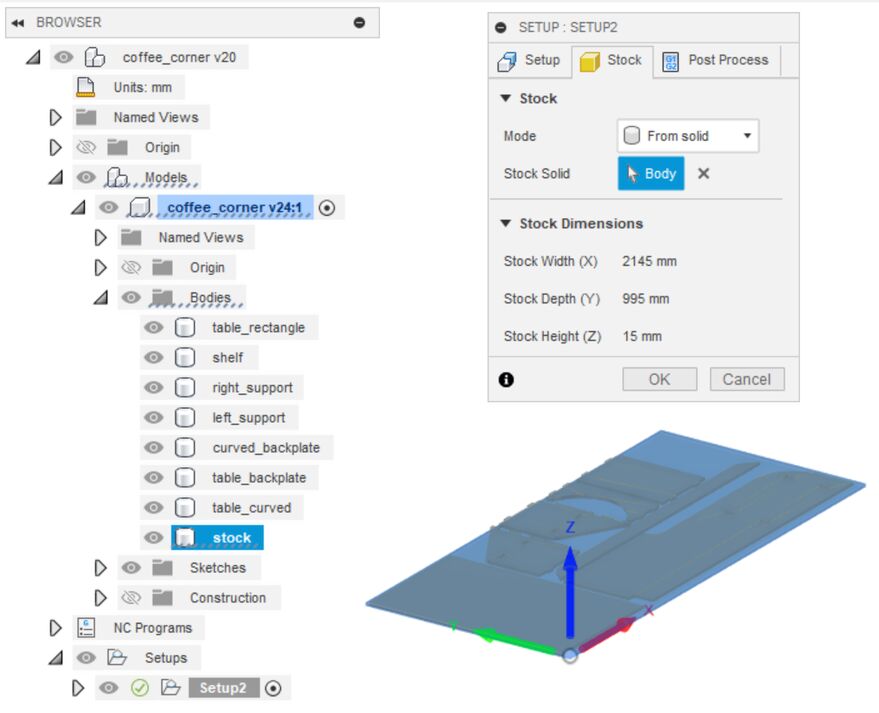 It's good practice to name the bodies in the model. It makes things easier.
Then in the Setup tab, I set up the work coordinate system. I set the zero point to be the bottom left corner of the sheet corner, looking at it from above (see the image above). The top surface is the Z reference.
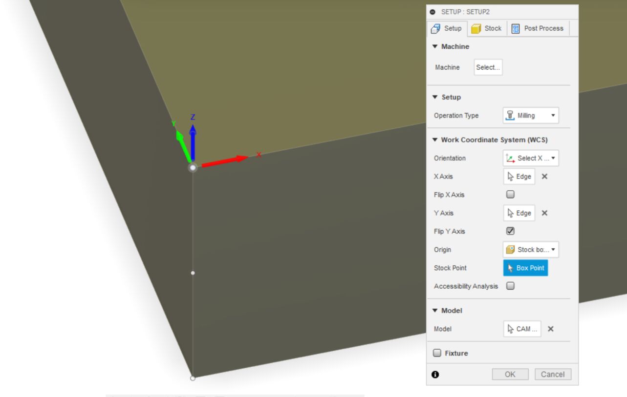 Close-up of how I define the work origin for the Shopbot.
Now I start creating machining operations. I had to create the chamfering tool in Fusion, it's not complicated.
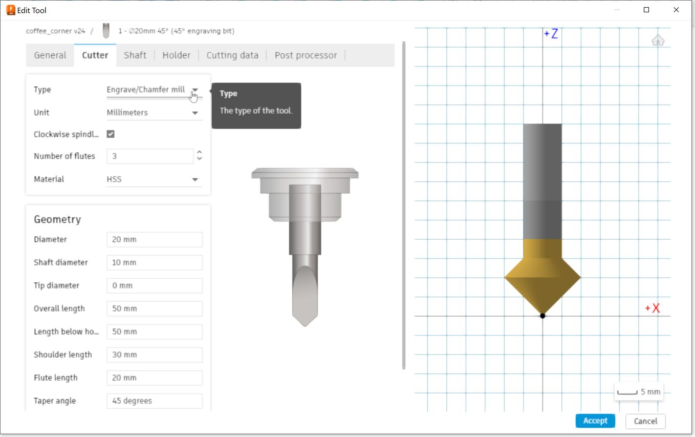 You can select the type of milling bit from a drop down list and then specify its dimensions according to the bit that you have.
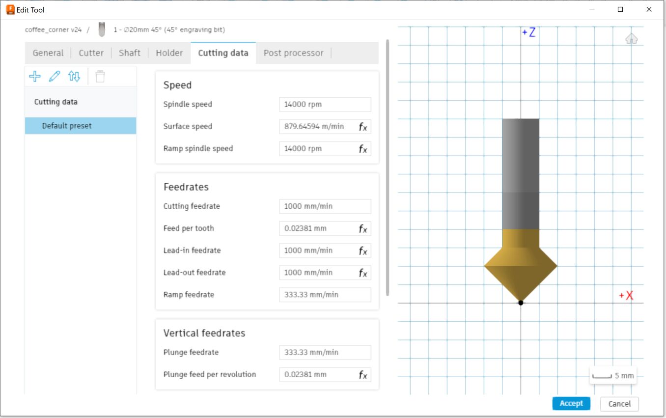 In the Cutting data tab you also input the feeds and speeds for this bit. Þórarinn recommended that for plywood I would choose a spindle speed of 14.000 rpm and a feed rate of 1000 mm/min.
Then I chose a 2D contour milling operation and selected only the edges that I wanted chamfered. For some reason it worked better to split the operations up and select only one edge in each one. Under the Passes tab, uncheck the Stock to leave option. The first pass is the finishing pass.
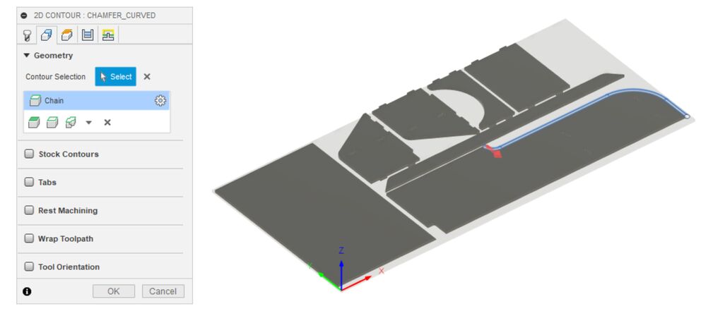
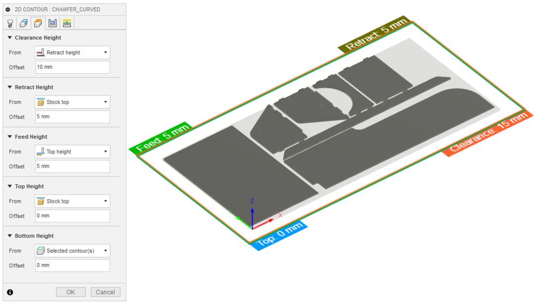 Remember to select Stock bottom as the bottom plane.
Next, I mill the dogbone press-fit holes. I select a 6 mm flat end mill with the same feeds and speeds as the chamfering tool. I created one 2D pocket operation for each dogbone pocket.
 The simulation looks good. I had to enlarge the circles in the dogbone to make sure that the milling bit can enter them.
The last operation is to mill all the outline, using the same 6 mm flat endmill, again rotating at 14.000 rpm and moving at 1000 mm/min through the material:
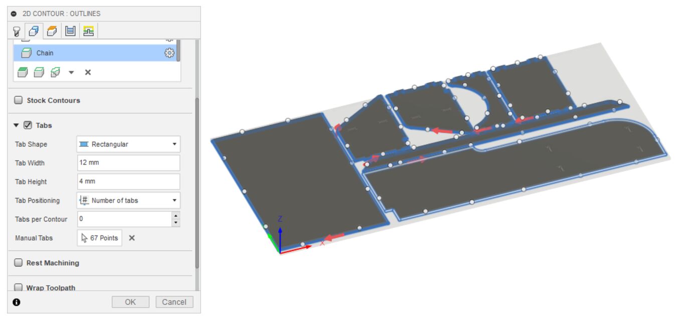 The outline milling operation. It's a 2D contour operation, like the chamfering. I had the machine leave rectangular shaped tabs, to keep the parts from moving around while finishing the milling operation.
The ShopBot
Specifications
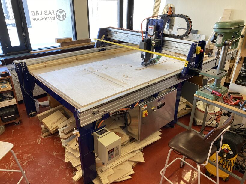 The ShopBot in Fab Lab Ísafjörður. The leftover wood under the machine is free to use for everyone.
We have a ShopBot PRSalpha 120-60 CNC. This is a big and capable 3-axis machine with a 3.28 m by 1.55 m work area and a 5 horsepower beast of a spindle. It has a cutting force of about 68 kg and it can move at up to 18 m/min across the table with the full cutting force.
The ShopBot has strong geared stepper motors with low backlash which move the gantry using a rack-and-pinion motion system. Þórarinn mentioned the other day that he isn't sure that the mechanical end stops will hold if the machine decides to move all the way to the end at full speed. The stepper motors have position sensors, so we have a closed-loop control system. The machine can correct the position of the motors in real time if they're a little bit off. The step resolution is 0.01 mm. If that's true in practice, then that's really nice.
The ShopBot has a convenient conductive metal plate that you can place on top of your sheet material and zero the Z-axis automatically.
The ShopBot is mostly used to make wood furniture and occasional molds for composite manufacturing, but also for milling engineering plastics and I used it successfully to mill a small and precise mold in Molding and Casting week. Þórarinn is also working on milling an experimental aluminum injection mold with a local engineer who does interesting projects in the lab. I'm interesting in learning to mill aluminum with the ShopBot. You have to be really careful with your feeds and speeds. I've milled two small branding irons out of brass using a V-bit, that was fun.
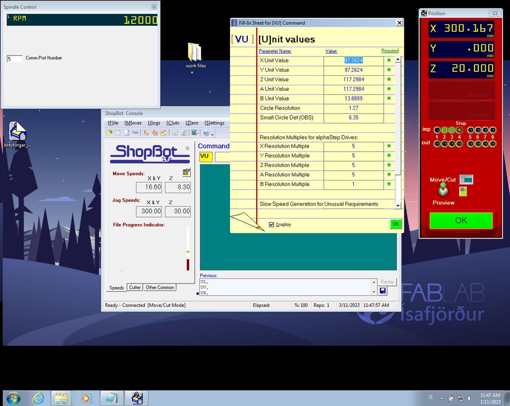
Turning the machine on
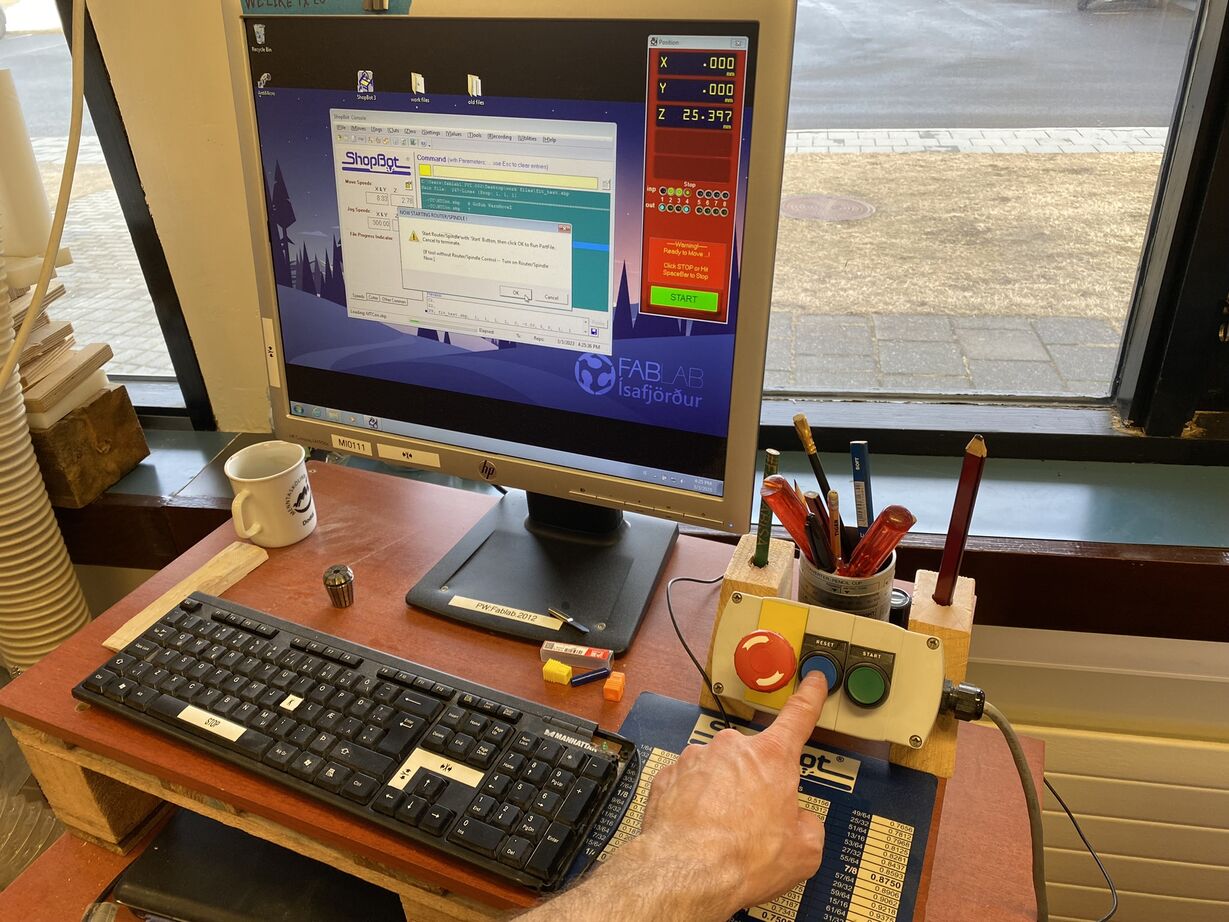 To be able to turn on the spindle, you need to reset the machine controller.
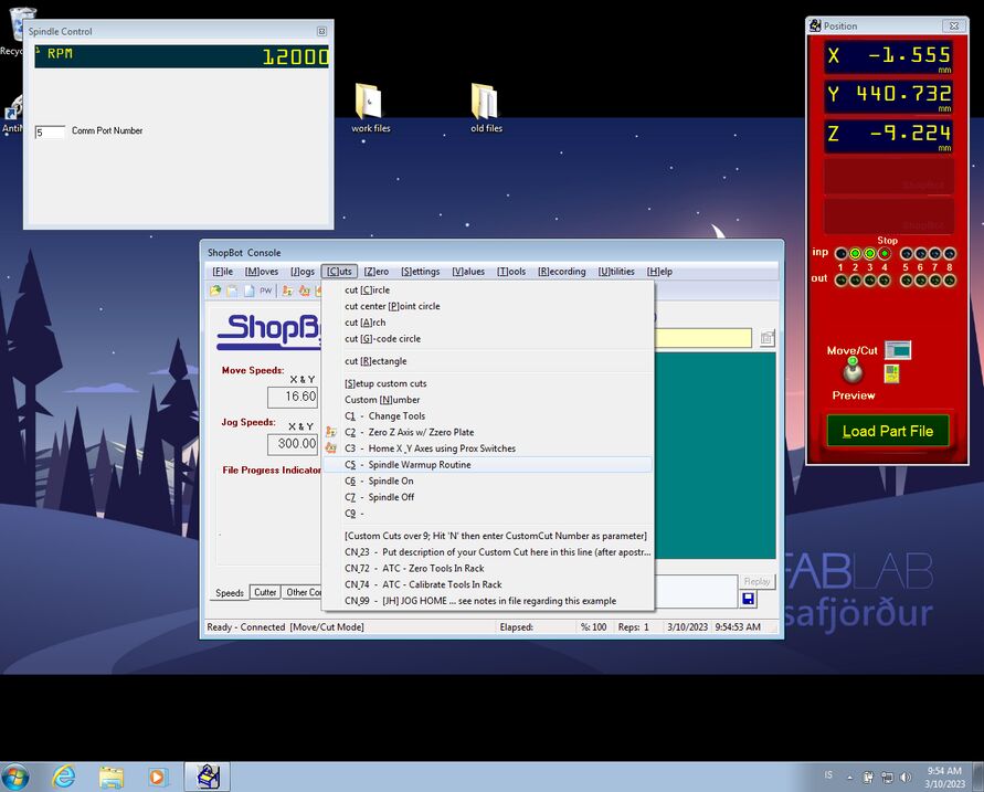 Before you do anything in the Shopbot control software, you need to open Tools -> Spindle control. Otherwise the software can't change the spindle speed as the GCode requires. Then you go into Cuts -> Spindle Warmup Routine, to spin the spindle at two speeds for 10 or 15 minutes, to warm up the bearings in the spindle.
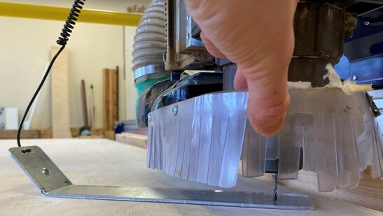 You go into Cuts -> Zero Z-axis w/ Zzero plate to zero the Z-axis with a conductive metal plate.
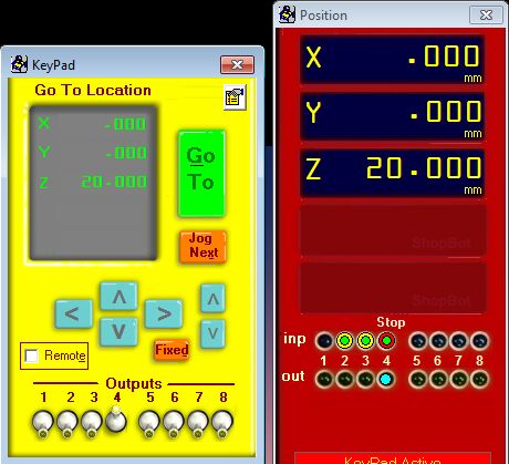 Then you press K to get the KeyPad window and use the arrow keys on the keyboard to move the spindle to a convenient point before you go into Zero -> Zero [2] axes (X & Y) in the software.
 Turning on the shop vac just before starting the job.
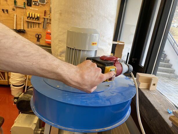
Recalibrating the ShopBot
When I made a fit test with two slightly different clearances, I discovered that both of them were way off the mark. I asked my instructor Þórarinn what might cause this and he suggested that the gearboxes on the stepper motors might be wearing out. This may result in the steps per inch value changing.
So I modeled a 100 mm by 100 mm square with a circular pocket in the middle. My instructor Þórarinn suggested that I also chamfer the corners, so that I could make diagonal measurements.
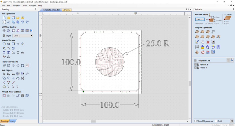
The resulting square had 100.5 mm sides. That means that I need to use this scaling factor on the steps per inch value. I can change that value in the Unit Values window in the Shopbot control software.
Corrected value:
steps/inch.
Let's change the unit values for the X and Y axes in the ShopBot control software:
 The X and Y unit values were 97.7487 and then I changed them to 97.2624.
Now our ShopBot is more accurate.
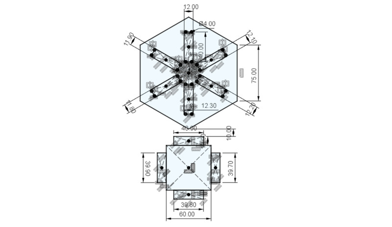
Test pieces
I designed a test fit piece with different clearances in Fusion 360.
These fit tests gave me the confidence to finish the design of the coffee corner and mill all the parts in one go.
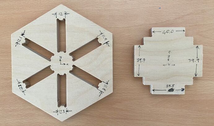 Hexagon fit test pieces.
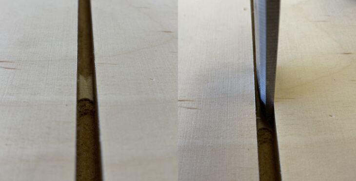
I also did a chamfering test, here's the CAM simulation:

I'm glad I also did this test, because I had selected a chamfering tool that was too small.
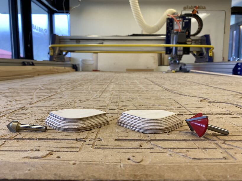 Both are 90° bits, but one is bigger than the other. And that makes a difference when you carve this deep.
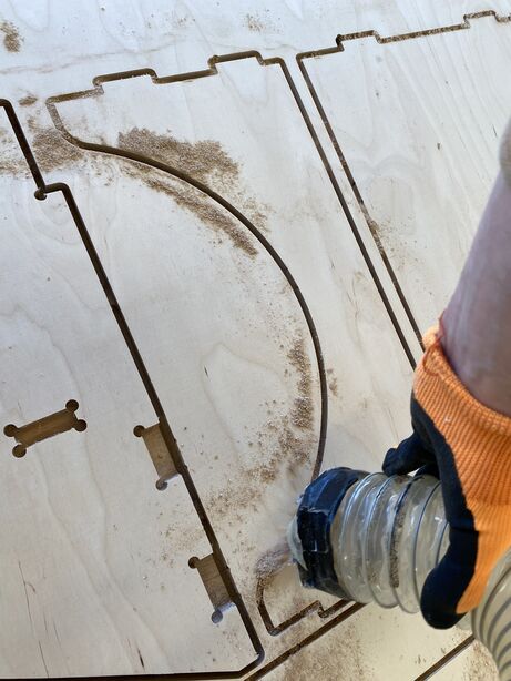
Milling the parts for the coffee corner
It was exciting to do sophisticated milling like this with confidence. I fixed the plywood sheet with screws in the corners and on the middle of the long sides. I took care to tie my hair into a bun and wear hearing protection and safety glasses. First I milled just the chamfers into the plywood sheet. Then I changed from the chamfer tool to the 6 mm flat end mill and milled the dogbone pockets. After that operation it still didn't look like anything recognizable. Finally I milled the outlines and then I recognized the parts.
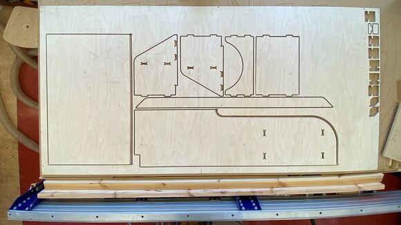 Top view after milling.
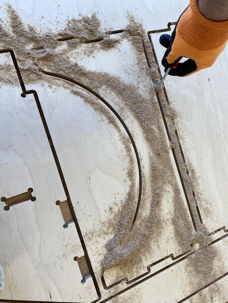 Dislodging the sawdust with a screwdriver.
 Vaccuuming the sawdust.
 Breaking the tab.
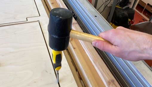 Breaking the tabs with a chisel.
 Sanding the edges.
I chamfered a few corners before hammering the parts together, to make sure that they sit flush against each other.
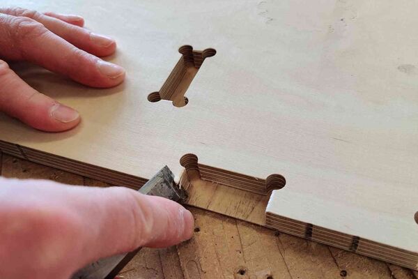 My instructor Þórarinn suggested that I take a little off the corners to compensate for the inner corner radius in the piece that gets hammered into these holes.
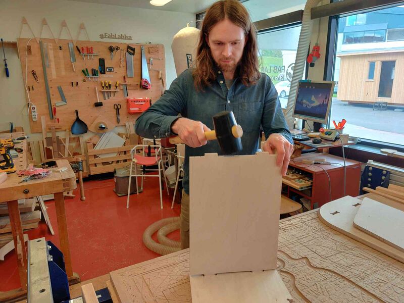 Hammering the parts together. They fit tightly together and don't require any glue.
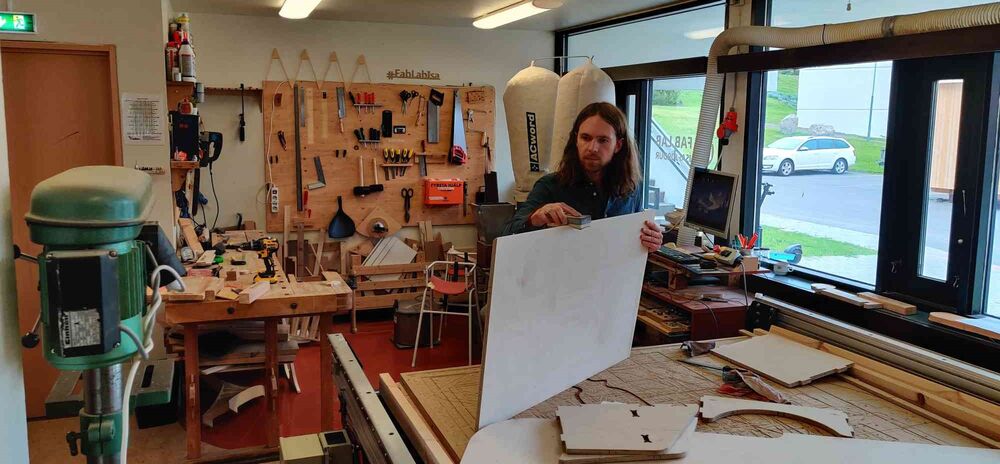
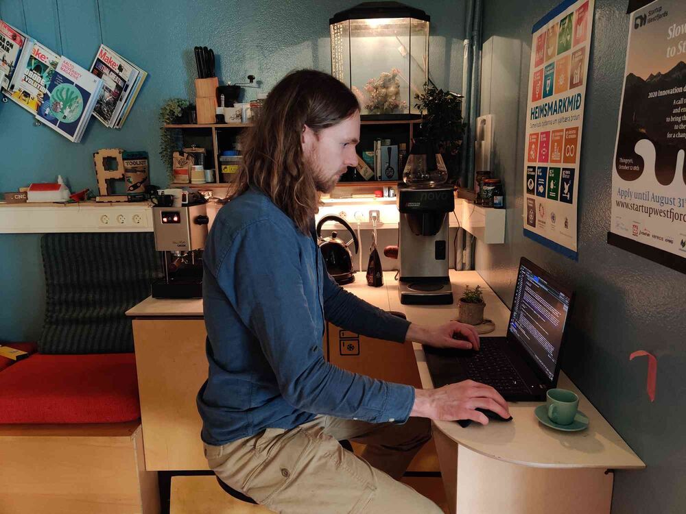 Our new documentation station. I really get in the zone when I sit here and write documentation. I think it's because I feel like I'm in a café, and that's where I get the best concentration. Look how serious I am!
The next time I mill something out of wood using Fusion 360, I may need to use a different tab shape. Look at the burn marks after the machine stopped to mill this tab:
 There are burn marks where all the tabs were.
While I was hard at work finishing up the documentation, my instructor Þórarinn painted the table black and attached it and the shelf to the wall.
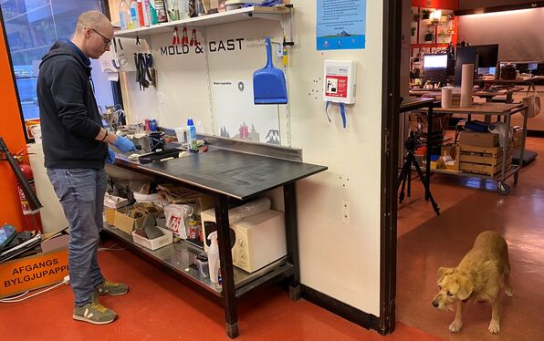 Bas Withagen in Fab Lab Reykjavík used to say that if you have time to paint your final project, you're doing it wrong. Fortunately, I have my trusty instructor Þórarinn, who painted the table black. He's there with his dog Sóla, who was old and had become blind from diabetes. She laid at my desk as I worked on the Fab Academy documentation. Sóla only lived for a week after I took this picture. Such a sweet dog.
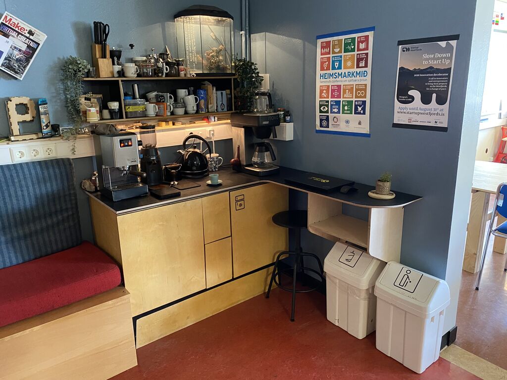 Our lovely coffee corner with a freshly painted table and Þórarinn's espresso machine. Þórarinn commented that now there was really no spot in the lab that wasn't cozy and enticing to sit down and work on a laptop.
All the design files
Download Coffee Corner Fusion 360 model
Download 12 mm fit test Fusion 360 model
Download 12 mm fit test - more clearance Fusion 360 model
Download 12 mm hexagon test Fusion 360 model
Download 15 mm fit test Fusion 360 model
Download 15 mm chamfer test Fusion 360 model
Download rectangle circle test VCarve file
Download rectangle circle test - quarter inch bit VCarve file