Hello ATtiny412 USB
I'm working on a version of Neil Gershenfeld's hello T412 boards that would be a good fit for primary school students in Ísafjörður. See Neil's boards here: Basic, output, input and networking. I'll use the ATtiny412 because it's so cheap that all the students can take their boards home with them. This microcontroller is also easy to solder.
Neil's board
I'm basing the board on Neil Gershenfeld's t412-blink-3 pin board. Its design files are on the Fab Academy 2023 Embedded programming page.
A student in my secondary school Fab Lab class drew up Neil's board in KiCAD, milled it on the Modela MDX-20 and soldered the components onto it. The board has a 10 uF decoupling capacitor for the ATtiny412. She programmed the board using Neil's Arduino sketch:
It blinks!
The student took the board home, but she doesn't have a USB to serial cable, so she can't power the board when she wants to.
Design spiral 1
So my first design modification was to add a USB breakout board to power the board anywhere:

It didn't work. When I measured it plugged into a USB power supply, I discovered that its polarity was reversed. Strange, I thought I had checked the polarity before milling. Anyway, lets swap +5V and GND and try again:
Here it is running Neil's Arduino sketch on USB power:
Design files
My student's board:
Download hello_t412_3_blink KiCAD project
Download hello_t412_3_blink traces PNG file
Download hello_t412_3_blink interior PNG file
The USB power breakout board:
Download usb_power_for_UPDI_MCUs KiCAD project
Download usb_power_for_UPDI_MCUs SVG file
Download usb_power_for_UPDI_MCUs traces PNG file
Download usb_power_for_UPDI_MCUs interior PNG file
Code:
Download Neil's Arduino sketch
Design spiral 2
Design spiral 2 was to put the USB connector on the board with the ATtiny412:
When working on this board I realized that I had turned the USB connector the wrong way on the USB breakout PCB and that had caused the reversed polarity. So I turned the USB connector the right way round this time and still got the polarity wrong.
Design spiral 3 (recommended)
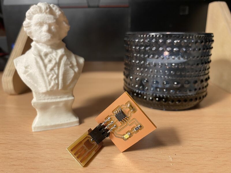
OK. Let's try again, and make the board nice and compact this time. And add a button, for good measure. That makes for more interesting programming exercises.
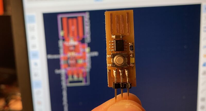
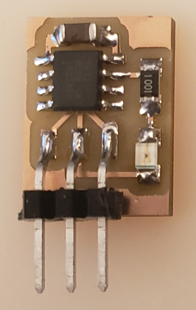
Components: ATtiny412, SMD button, 1000 Ohm resistor, LED (any color), 3 pin SMD header (use pliers to break 3 pins off), all from the Fab Lab Inventory.
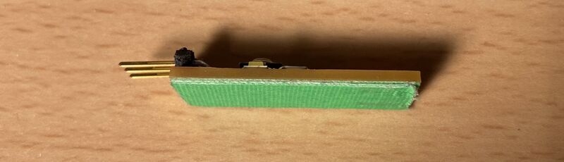
I put three layers of cloth tape on the back of the board, so that it fits snugly into the USB port. Any tape will do, just keep adding layers until the board stays connected inside the USB port.
To be able to use the ATtiny412 chip, you need to install the Arduino IDE (preferably version 1.8.13) and then install the MegaTinyCore.
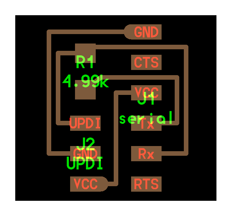
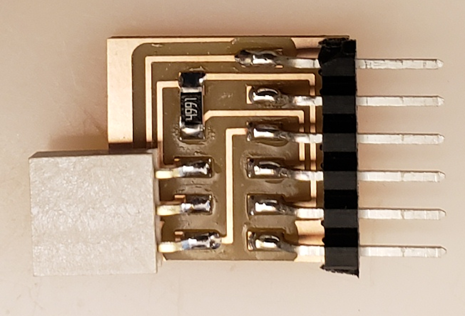
To connect the board to the computer, plug Neil's serial UPDI-3 pin board (pins, components, traces, traces+exterior, interior) to an FTDI cable like you see in the video at the top of this page (take care to get the wire colors right).
I used the DigitalInputPullup example sketch to get the button working. Then I added a boolean logic variable and inverted its value when the button is pressed. This way, I can toggle the LED.
The code didn't work the first time around because the button bounces when I press it, and that toggles the LED many times. As a quick fix, I added a 200 millisecond delay. I left it like that for a while because it worked OK for me.
When my 6 year son soldered a board and tested it, the button action didn't work well for him. So I looked around and the inbuilt Arduino debounce example works better than my code did. So I just changed the pin numbers to match my board:
/*
  Debounce

  Each time the input pin goes from LOW to HIGH (e.g. because of a push-button
  press), the output pin is toggled from LOW to HIGH or HIGH to LOW. There's a
  minimum delay between toggles to debounce the circuit (i.e. to ignore noise).

  The circuit:
  - LED attached from pin 13 to ground through 220 ohm resistor
  - pushbutton attached from pin 2 to +5V
  - 10 kilohm resistor attached from pin 2 to ground

  - Note: On most Arduino boards, there is already an LED on the board connected
    to pin 13, so you don't need any extra components for this example.

  created 21 Nov 2006
  by David A. Mellis
  modified 30 Aug 2011
  by Limor Fried
  modified 28 Dec 2012
  by Mike Walters
  modified 30 Aug 2016
  by Arturo Guadalupi

  This example code is in the public domain.

  https://www.arduino.cc/en/Tutorial/BuiltInExamples/Debounce
*/

// constants won't change. They're used here to set pin numbers:
const int buttonPin = 2;    // the number of the pushbutton pin
const int ledPin = 4;      // the number of the LED pin

// Variables will change:
int ledState = HIGH;         // the current state of the output pin
int buttonState;             // the current reading from the input pin
int lastButtonState = LOW;   // the previous reading from the input pin

// the following variables are unsigned longs because the time, measured in
// milliseconds, will quickly become a bigger number than can be stored in an int.
unsigned long lastDebounceTime = 0;  // the last time the output pin was toggled
unsigned long debounceDelay = 50;    // the debounce time; increase if the output flickers

void setup() {
  pinMode(buttonPin, INPUT_PULLUP);
  pinMode(ledPin, OUTPUT);

  // set initial LED state
  digitalWrite(ledPin, ledState);
}

void loop() {
  // read the state of the switch into a local variable:
  int reading = digitalRead(buttonPin);

  // check to see if you just pressed the button
  // (i.e. the input went from LOW to HIGH), and you've waited long enough
  // since the last press to ignore any noise:

  // If the switch changed, due to noise or pressing:
  if (reading != lastButtonState) {
    // reset the debouncing timer
    lastDebounceTime = millis();
  }

  if ((millis() - lastDebounceTime) > debounceDelay) {
    // whatever the reading is at, it's been there for longer than the debounce
    // delay, so take it as the actual current state:

    // if the button state has changed:
    if (reading != buttonState) {
      buttonState = reading;

      // only toggle the LED if the new button state is HIGH
      if (buttonState == HIGH) {
        ledState = !ledState;
      }
    }
  }

  // set the LED:
  digitalWrite(ledPin, ledState);

  // save the reading. Next time through the loop, it'll be the lastButtonState:
  lastButtonState = reading;
}
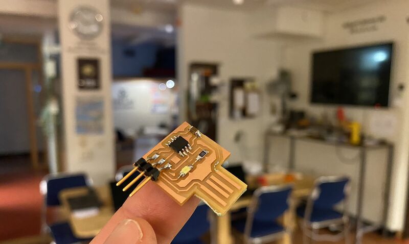
This is a nice minimal board that makes for a good first project:
Design files
Download hello_LED_USB-2 KiCAD project
Download hello_LED_USB-2 SVG file
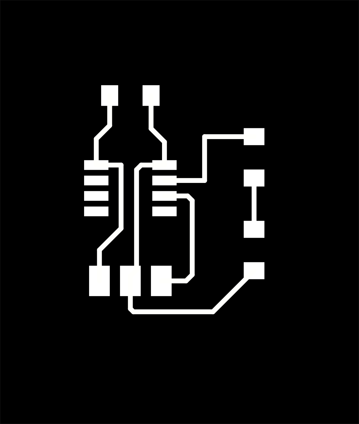
Download hello_LED_USB-2 traces PNG file
Download hello_LED_USB-2 interior PNG file
Design spiral 4 (abandoned)
Adding inputs and outputs
Now I want to expand the board a little bit, so that students can connect sensors to it.
I'll make a board that breaks out all the pins of the ATtiny412. I think I'll try to make something similar to Adrian Torres' Adrianino ecosystem, which is based on Neil Gershenfeld's classic hello boards. It might also be a good idea to make it compatible with the Keyestudio 37 in 1 Sensor Kit that we have at the lab. That makes for a quick way to try out a lot of sensors.
Note
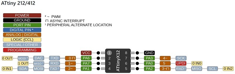 If I use pin PA1 for TX instead of the default PA6 pin, then I can break out the DAC on pin 0. If I have room to route it, that is.
Power and ground take up two pins on the microcontroller. If I put a button and an LED on the board, that uses up two pins. If I also do software USB communication and chip programming using the TX and RX pins, then I only have two IO pins left. One of those pins is the UPDI programming pin, so programming via USB had better work. Two IO pins is not a lot, but they should be enough to do a few interesting things. And the board stays tiny!
Adding bit-banged USB communication
Using sensors with the board requires a serial connection to a PC, so that you can get the sensor values in the serial monitor.
Warning
If I run the ATtiny412 at 3.3V for USB communication, it might be incompatible with the Keyestudio sensor kit. Remember to check the sensor voltage before continuing with design spiral 3.
Direct USB communication would simplify the board's pinout and enable to program the board at home, so I'm looking into V-USB. This thread has practical info on software USB communication with the ATtiny45 and I can use it with minor modifications for the ATtiny412. The thing that complicates the board design is that USB power is 5V but USB logic is 3.3V. I'm thinking that I'll put a 3.3V regulator on the board and run the ATtiny412 on 3.3V. That way I can do USB communication at the right voltage.
Two solutions to the voltage problem are listed in the V-USB hardware considerations. Solution A is to reduce the supply voltage for the microcontroller. The ATtiny412 can run at 3.3V, so I put a 3.3V regulator on this board:
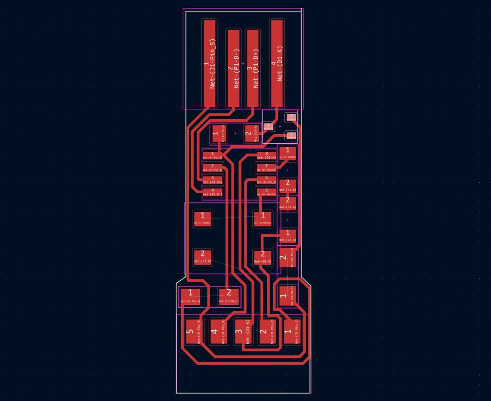 USB board with a 3.3V regulator (highlighted) for the ATtiny412.
The board is as compact as I could make it. I even reduced the size of the pads for the button. All I had to do was to select the button footprint and press Ctrl+E. Then I made the pads smaller and saved the footprint with Ctrl+S. That only saves the modification for this board, but doesn't change the footprint in the library. I followed this tutorial.
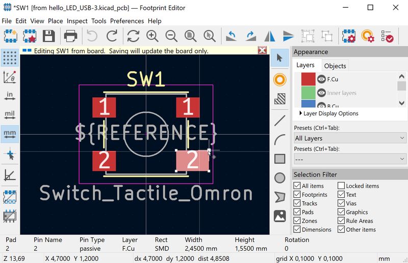 Notice the yellow banner that says: "Editing SW1 from board. Saving will update the board only."
When the design was finished, I read further and saw that the microcontroller needs to run at a minimum of 12 MHz. In the ATtiny412 datasheet I discovered that the clock only goes up to 10 MHz when the supply voltage is 3.3V. OK. So I need to throw out the regulator and go with solution B in the V-USB hardware considerations.
Useful documentation on the ATtiny412 from Fab Academy students is here and here. The FabFTDI is also interesting, because it uses the ATtiny45 with the V-USB library for software-only USB communication.
Update
I'm in a rabbit hole. As I kept reading about V-USB, the complexity of this tiny project grew. I need to set up the AVR-GCC toolchain and dependencies, modify a make file, set fuses and what not. While I do want to try that at some point, that is not the right thing for my secondary school students. So this is where spiral 3 stops, at least for now.
Adafruit reports that the bit-banged USB stuff is becoming increasingly incompatible with modern PC-side USB controllers (well, the other way around), urging people away from the Tiny85 "ArduinoLike " products. - AVR Freaks post by user westfw