Input Devices 
Assignment
Individual assignment
- Measure something: add a sensor to a microcontroller board that you have designed and read it
Group assignment
- Probe an input device's analog levels and digital signals
See more info and recording of the lecture here.
IR sensor board
I used the IR phototransistor from the fab library twice, to represent both the IR emitter and the phototransistor. For this board I'm using obsolete parts from the 2012 Fab Lab inventory that still work really well; the OP280KT IR emitter and the matched OP580 phototransistor. They are have a more square shape than their modern counterparts, but I checked the datasheets and their footprints are close enough to what I have in the KiCAD library now.
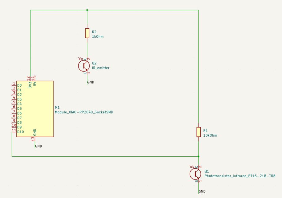 My Xiao IR sensor schematic.
I looked at the phototransistor board on the Xiao page of the Fab Academy web site of Adrian Torres. It has a 1kOhm resistor on the IR emitter diode and a 10kOhm resistor on the IR sensor. I did the same here.
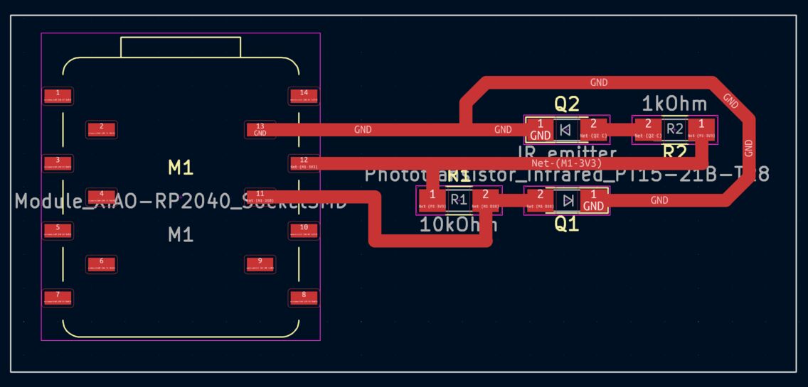 My Xiao PCB design for the IR emitter and sensor.
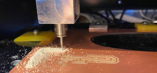
Instead of soldering the Xiao onto the board I'm using pin sockets. The milling went well using Fab Modules and the Roland Modela MDX-20, but the edges of the traces are a little bit rough. That's a sign of wear on the 1/64 inch bit.
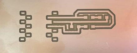 Milling the traces of the IR sensor board.
Then I milled the board outline with the 1/32 inch bit.
 Milling the outline of the IR sensor board.
Here's how the board looks:
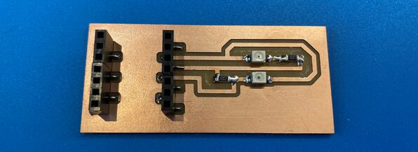 The IR sensor board.
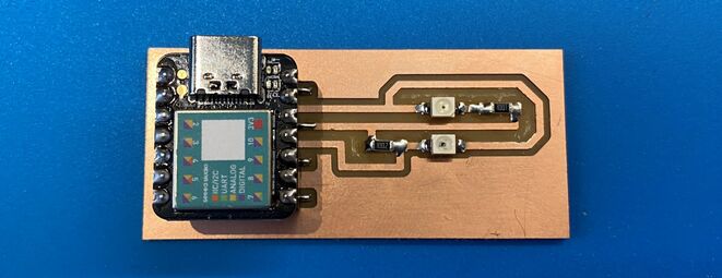 With the Xiao SAMD21 on board.
Here's a video of the sensor readings, it works really well:
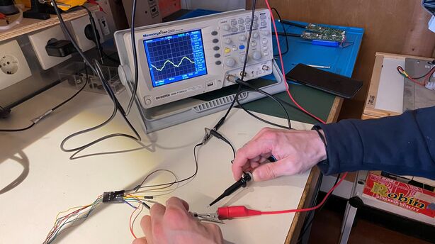
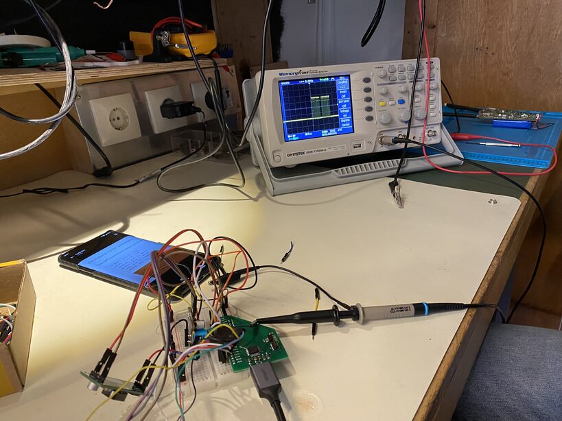
Measuring the analog signal
I connected the signal from the IR sensor to the oscilloscope and got a reading that changed with the light hitting the sensor:
Design files
I used code from Adrian Torres to get readings in the serial plotter, but I changed the number of the analog read pin to A10.
Here's my KiCAD project:
And the PCB milling files for Fab Modules or Mods:
 The traces.
 The interior (for milling the board outline).
And the Arduino code:
Download IR sensor Arduino code
Magnetic encoder
The board that I made for output devices has three pins that are intended for encoder input. I connected the encoder and wrote a simple test program in the Arduino IDE. The AS5048 encoder has a three-pin PWM output and a five-pin SPI output. I used the simpler PWM output. It was easier to route the board for those connections. In this case, I use the pulseIn Arduino command to read the length of the pulses coming into the pin from the encoder. Then I print the value to the serial monitor. Here's the whole program:
const int encoder = 3; // AMS AS5048 encoder
int pos=0; //mechanical position of shaft

void setup() {
  Serial.begin(9600);
  pinMode(encoder, INPUT);
}

void loop() {
  pos=pulseIn(encoder,HIGH);//read encoder pulse
  Serial.print(pos);
  Serial.print('\n');
  delay(10);
}
And here's a video of it running:
Then I connected the current sensing resistor of each H-bridge to a pin on the Xiao RP2040. Using analogRead, I was able to measure the current going through the motor! There is one value for each H-bridge, and the values are similar. The values fluctuate, so they depend on when the measurement is made.
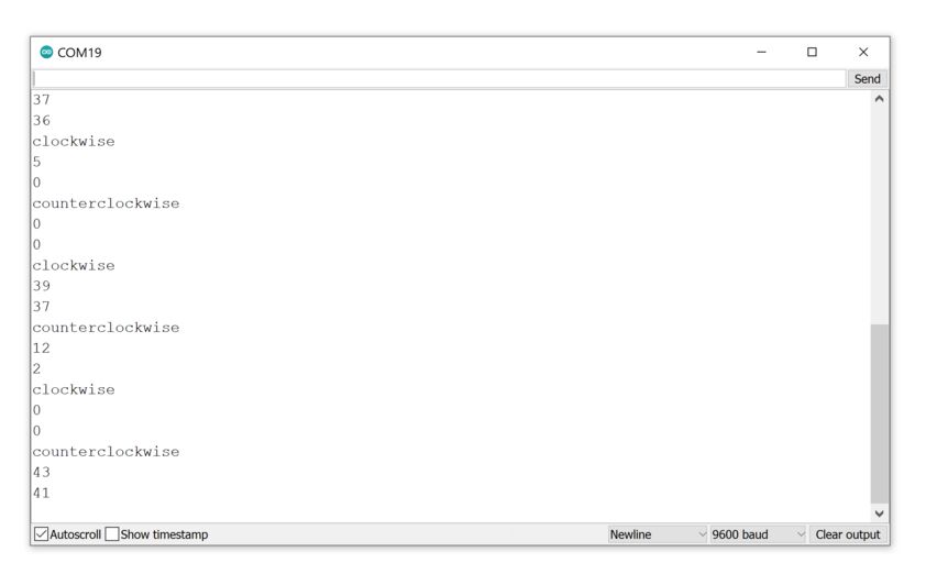 It seems to work!
Measuring the digital signal from the encoder
I measured the SPI signals coming out of the AS5048 magnetic encoder. The first thing to measure is the clock signal. This is what synchronizes the SPI communication.
 The clock signal from the A5048 magnetic angle sensor was weak.
I thought that maybe the magnetic encoder chip wasn't supposed to generate a clock signal. In SPI communication, there's only one main IC, and it generates the clock signal. So I connected the encoder up to a SAMD21 chip (and also connected the motor driver).
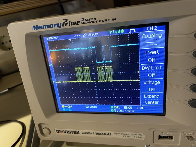
 With the microcontroller connected, the clock signal is strong. But its shape is surprising. I thought it would just be a regular square wave with no gaps.
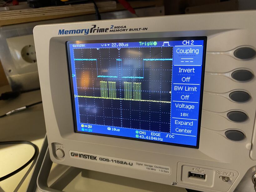
Next up is the chip select pin. The chip select pin is used to select between secondary SPI nodes, if more than one are connected to the same main microcontroller. This is how the chip select signal looks:
 The chip select signal in blue, overlaid onto the clock signal in yellow.
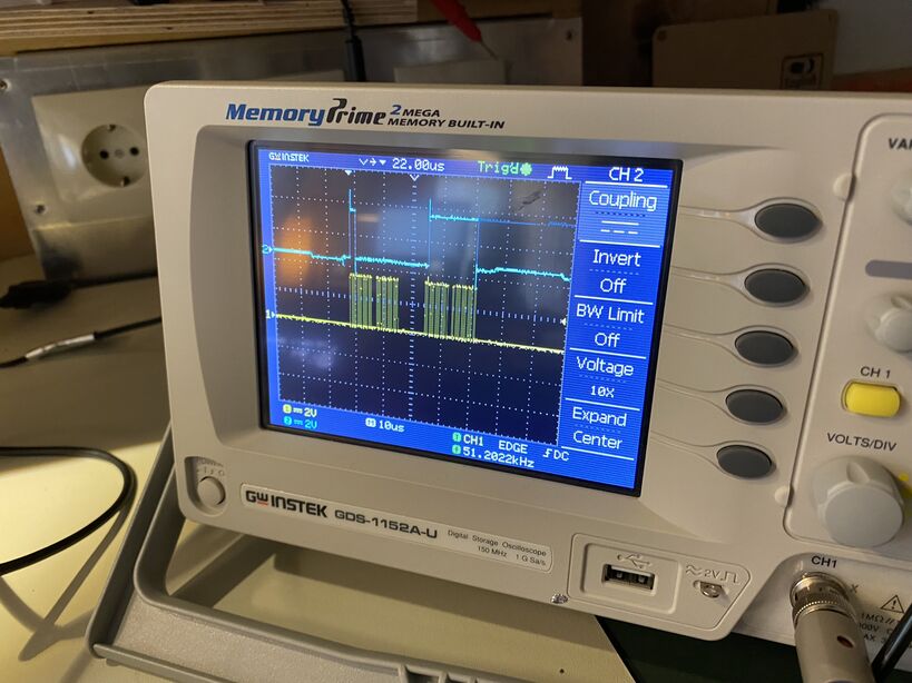
Then there's the data, MOSI and MISO.
 The MOSI signal. I tried rotating the motor while it was on the screen. I didn't see any significant changes. But the angle still appeared in the serial monitor.
 The MISO signal. Some disturbances happened when I turned the motor, but I couldn't see how the signal was coming across the wire.