Networking and Communications 
Assignment
Individual assignment
- Design, build, and connect wired or wireless node(s)
- with network or bus addresses and a local interface
Group assignment
- Send a message between two projects
See more info and recording of the lecture here.
Hello I2C
I did this week's work in Neskaupstaður, which is as far as you can get from Ísafjörður in Iceland. I had to take two flights to get there! The annual Icelandic Fab Lab Bootcamp was held in Neskaupstaður this year. I think everybody got lots out of it and this was the first time that we set up a repo and a web site for an Icelandic bootcamp. We're under the influence of the 2023 Instructor's Bootcamp in Amsterdam.
This is what I packed for the trip (plus a few items of clothing and a toothbrush):
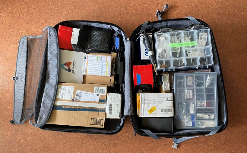 I brought a large part of our electronics inventory, just in case.
I decided to do as Hafey did, and make Adrián Torres's Hello I2C boards. The project consists of a master module which sends an I2C message and two nodes that receive the message and turn on an LED.
I read up on how I2C works. SparkFun's article on I2C is really good.
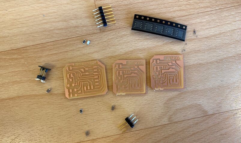 I milled Adrian's boards and populated them with components. Hafey brought ATtiny412 ICs for me from Fab Lab Reykjavík.
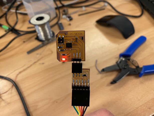 I2C node with adapter.
For my own board I decided to use a laser diode. I had wanted to try one of those since I saw Árni Björnsson's output devices video.
 My laser diode, powered directly by the lab power supply. I noticed that it has an SMD resistor soldered onto it, so I don't need to worry about limiting the current.
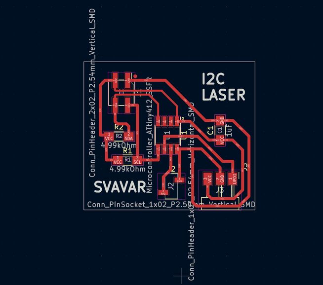 My I2C laser diode PCB design.
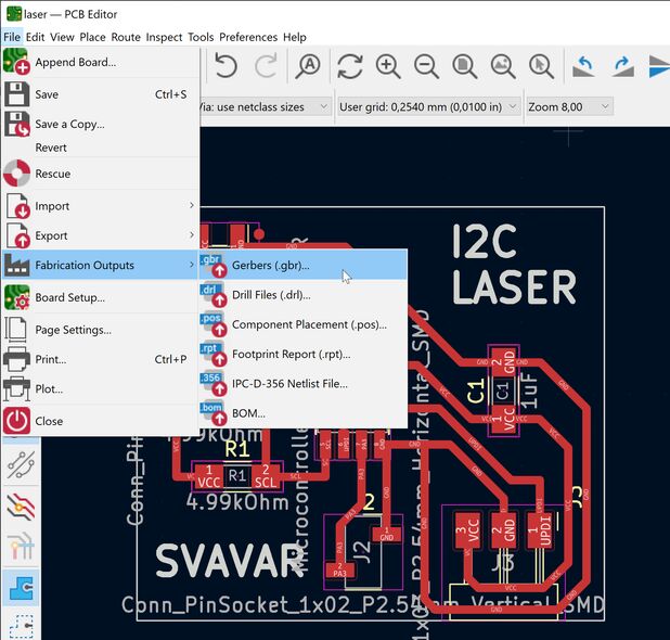 I tried the Gerber output for the first time.
I tried FlatCAM, which went well, but the toolpath left thin strips of copper in between the traces. I would need to adjust the settings before milling again. It also didn't mill the text on the board, but I didn't really care about that.
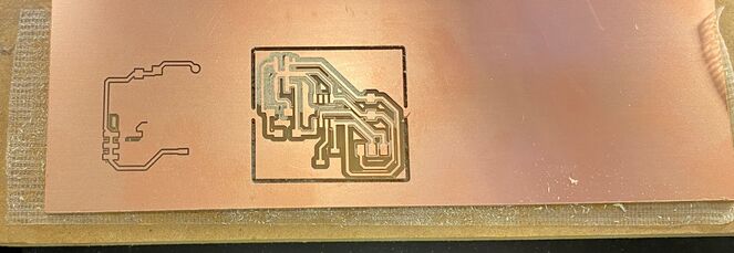 My laser diode I2C board after milling. In this milling machine, the FR1 PCB blanks are fastened to the wasteboard with double-sided tape.
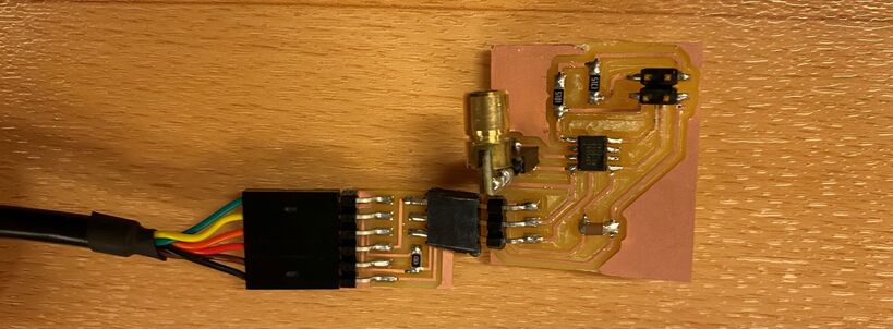 Here's my I2C laser board populated and connected to the adapter.
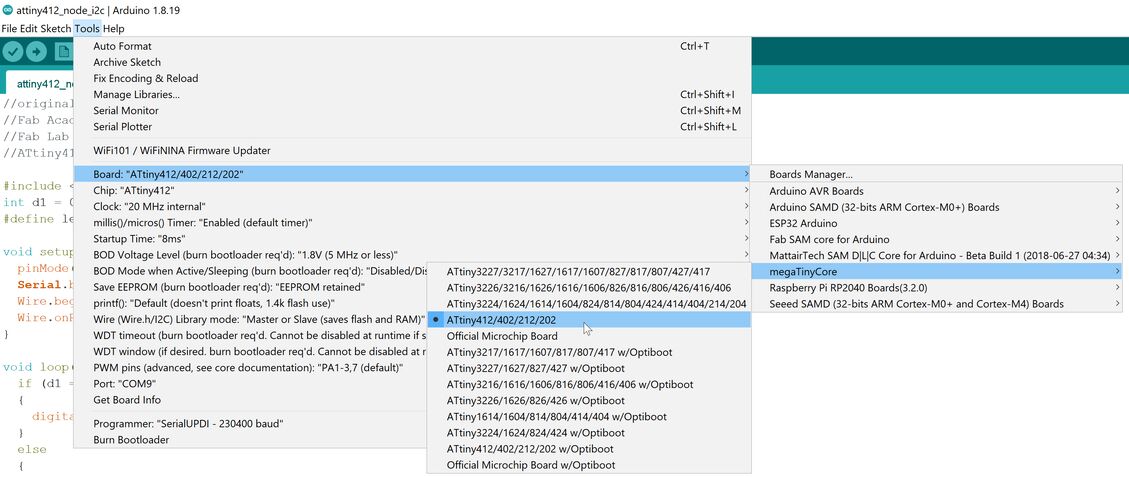
Before programming the board, I had to install the megaTinyCore, which enables the Arduino IDE to program the ATtiny412.
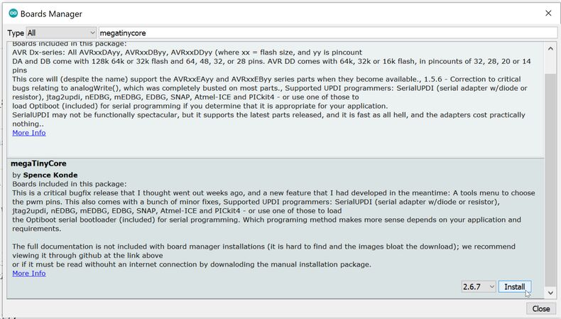 I went into Tools -> Board -> Boards Manager and searched for megatinycore and installed it.
Then I went into Tools -> Board and selected the ATtiny412:
Hafey pointed out to me that Adrian's Arduino code had an error. The master node was set up to send a message to one node, and then another. But the number of the node was the same in both cases: the command Wire.write(1) was in both places. After changing the second one to Wire.write(2), the code worked.
Hafey also showed me that instead of using the Upload arrow, now I needed to go into Sketch -> Upload Using Programmer.
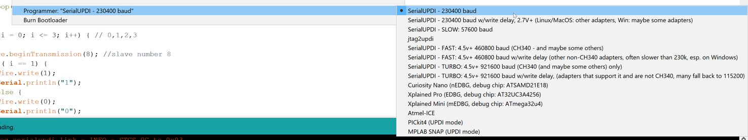 First select Tools -> Programmer -> SerialUPDI - 230400 baud.
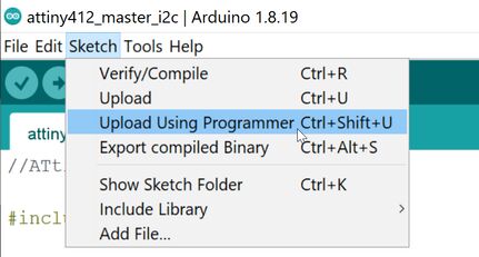 Then select Sketch -> Upload Using Programmer.
Upload Using Programmer didn't work. Hafey suggested that I just try again. Then it worked.
Debugging
However, the LED didn't turn on. I don't know why. I noticed that one of the legs of the female header that the laser diode was plugged into had come loose off the board. I tried pushing on it to reestablish the electrical contact, but ended up breaking the female header completely off the board. My instructor Þórarinn suggested that I try connecting the laser diode to the 5V power rail on the board and GND, just to see if the board can supply it with enough power.
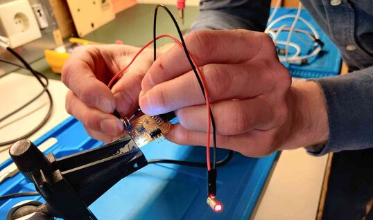 USB power is OK on Adrián's I2C Master board. I also tried this on my board and it worked too.
Then I connected Adrián's board to mine over I2C and plugged his board into a USB port to power it. I connected a multimeter to the broken leads for the laser diode and watched for a while. There was no voltage. Nothing was happening on the pin. This must be a software issue.
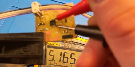 Just a quick check whether the microcontroller is gettning 5V. Good.
Just to see if the laser diode pin worked, I uploaded the Arduino Blink example to my board and connected the laser diode. It worked! Then I uploaded the node 1 I2C Arduino sketch onto my board, which is exactly the same code as the one that runs successfully on Adrián's board. Nothing. OK, better check the I2C connections on the board. The message may not be getting all the way to my microcontroller.
Aha! There's no continuity between the I2C pin header and the SCL pin on the microcontroller. My instructor Þórarinn suggests only using continuity checking as a last resort, so we brought out the oscilloscope.
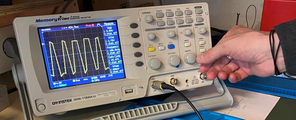 We measured a short SDA signal every second at 100 kHz.
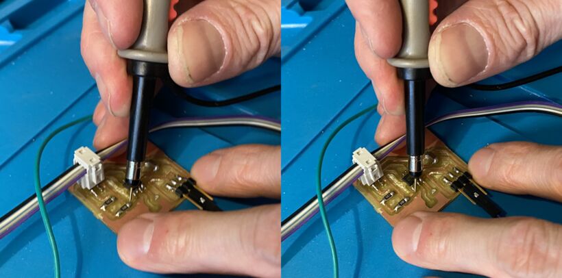 With voltage measurements along the trace we found that it was broken near the microcontroller.
I put some solder onto the trace to bridge the gap, connected the boards together and - nothing. Oh, I still had the Blink program on my board! I reuploaded the I2C node code and - nothing. Hm.
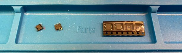 Dead bugs. One thing that I ran into was that when I was measuring with the multimeter, I accidentally shorted between two tracks and the ATtiny412 became unresponsive. This happened on Adrián's board and my own. I've become quite adept at swapping out ICs with the heat gun. Gotta be more careful with these delicate parts. Lesson learned.
After swapping out the unresponsive ATtiny412 for a new one, my board finally worked! I soldered the female header back onto the board and here it is in all its glory:
Success!
If you listen carefully, you can hear a giant cruise liner signaling its departure from Ísafjörður at the beginning of the video. We had two and three of them visit the town per day this summer, each carrying more passengers than the population of our town.
Design files
Download I2C laser KiCAD project
Fab Modules
When discussing Fab Modules/Mods/Mods Project at the Fab Lab Bootcamp in Neskaupstaður, few of our colleagues thought it was a little bit strange to turn vector drawings into bitmaps before running them through the CAM software. But Frosti told me that Neil had mentioned at some point that CNC machines operate on a bitmap grid in the end. That's a good point. We're using Computer Numerical Control, not Computer Vector Control. The G-codes are all encoded as Cartesian coordinates with finite precision. So if you use a high enough resolution in the PNG image, you shouldn't lose any accuracy. The workflow works well, and I like using the old Fab Modules that we have running locally on a Linux laptop.
Late in the evening I wanted to make the UPDI adapter that I needed to connect my Hello I2C boards to the computer. Frosti took the opportunity to open up Mods Project. After tweaking a few settings and figuring out that we needed to turn on the Save module and then click Calculate again to get an RML export, the milling went great! We just needed to set the file type to RML1 in the Roland control software, instead of RML NC code.
microSD breakout board
This video might be useful. It shows how to solder wires directly to an SD card to communicate with it. So the passive components on commercial SD breakout modules aren't strictly necessary, although I'm sure they make the communications more reliable.
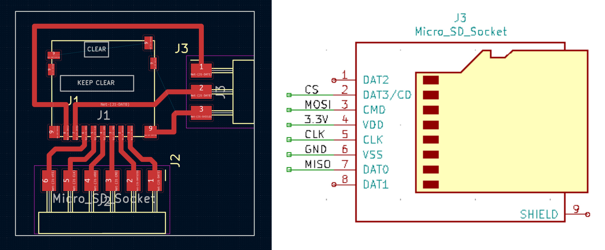 The PCB layout of my microSD card breakout board on the left and Janet Liu's schematic on the right. Her schematic shows which SD card pin matches which SPI pin on this particular SD card holder from Amphenol. You need to open the image in a new tab to see the pin names on my PCB layout.
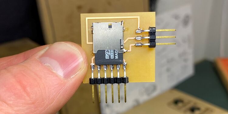 I didn't consider which way you put the SD card into the slot, so now that I've soldered the headers onto the board, the microSD card is stuck there for all eternity. I hope I can at least communicate with it.
I tried going through this clear tutorial by Shawn Hymel. But since he published it, the MicroPython SD card library has disappeared from the GitHub. So I stopped there. I'd like to revisit this later.