Computer-Aided Design 
Assignment
- Model (raster, vector, 2D, 3D, render, animate, simulate, ...) a possible final project,
- compress your images and videos,
- and post a description with your design files on your class page.
See more info and recording of the lecture here.
Raster image editing
My instructor Þórarinn gave me a quick demo of how to isolate an object in an image and make the background transparent. That will probably come in handy in many situations. We'll use Photopea, a free online (and downloadable) photo editor that closely resembles Photoshop. You can even go through Photoshop tutorials in Photopea.
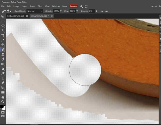
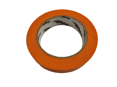
Let's start by taking a picture of a roll of tape with flat lighting, and we'll try to avoid having shadows. I'll use the magic wand to select pixels with the a similar color as the pixel under the mouse. Then I'll invert the selection and finally I'll make a mask.
Next I will use the brush tool to remove the rest of the background. I can hold Alt and the right mouse button to adjust the size and softness of the brush.
Now I brushed away the rest of the background. But sometimes I accidentally brush away part of the object.
Tip from Þórarinn: If you brush away too much, you can press X and switch to the other color in the mask. Then you can brush the object back into the picture.
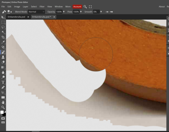
Finally, it can be good to add a color fill layer. It can make it easier to see spots that you missed with the brush. You need to drag the color layer below the image layer in the menu on the right. Then the color is behind the image.
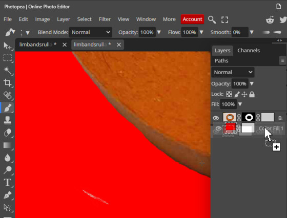 Missed a bit!
Raster image compression
To compress the images for the web I installed ImageMagick for Windows from the website. The installation included FFmpeg. I couldn't find any info on the website on how to get started (for someone who doesn't use command line tools), but then I came across Aaron Logan's Fab Academy site from 2022. He recommended following along with this video and that did the trick for me. It was useful to see the trick of writing cmd in the address bar of the folder that includes the images, and then the Windows Command Prompt opens in that directory.
Failure
I entered
magick convert 2023-02-02 15_22_45-Photopea _ Online Photo Editor.png -resize 40% -quality 80 output2.jpg
convert: unable to open image '2023-02-02': No such file or directory @ error/blob.c/OpenBlob/3569.
convert: no decode delegate for this image format `' @ error/constitute.c/ReadImage/741.
convert: unable to open image '15_22_45-Photopea': No such file or directory @ error/blob.c/OpenBlob/3569.
convert: unable to open image '15_22_45-Photopea': No such file or directory @ error/blob.c/OpenBlob/3569.
convert: no decode delegate for this image format `' @ error/constitute.c/ReadImage/741.
convert: unable to open image '_': No such file or directory @ error/blob.c/OpenBlob/3569.
convert: unable to open image '_': No such file or directory @ error/blob.c/OpenBlob/3569.
convert: no decode delegate for this image format `' @ error/constitute.c/ReadImage/741.
convert: unable to open image 'Online': No such file or directory @ error/blob.c/OpenBlob/3569.
convert: unable to open image 'Online': No such file or directory @ error/blob.c/OpenBlob/3569.
convert: no decode delegate for this image format `' @ error/constitute.c/ReadImage/741.
convert: unable to open image 'Photo': No such file or directory @ error/blob.c/OpenBlob/3569.
convert: unable to open image 'Photo': No such file or directory @ error/blob.c/OpenBlob/3569.
convert: no decode delegate for this image format `' @ error/constitute.c/ReadImage/741.
convert: unable to open image 'Editor.png': No such file or directory @ error/blob.c/OpenBlob/3569.
convert: unable to open image 'Editor.png': No such file or directory @ error/blob.c/OpenBlob/3569.
convert: no images defined `output2.jpg' @ error/convert.c/ConvertImageCommand/3342.
I guess ImageMagick didn't like the file name that the Greenshot screen grabbing tool generates. My instructor Þórarinn recommended Greenshot to me, it's lightweight and because it freezes the screen, you can grab screenshots where your mouse shows up. I tried renaming one of the files to 1.png and then the ImageMagick compression command worked:
C:\code\FabAcademyImagesUncompressed\week02>magick convert 1.png -resize 40% -quality 80 output1.jpg
mogrify doesn't copy the images but changes the originals. So I just make copies of them first and put them all in one folder before running the mogrify. Here's the mogrify documentation.
To resize and compress single images as I go along, I use
Design file
Here is the finished product:
3D modeling in Blender
Since I can generally get Fusion 360 to do what I want it to, I decided to learn a little bit about Blender. I've been missing a way to edit STL meshes and model organic stuff, so here we go.
Right after you click Download, this Youtube tutorial series appears on the Blender website. So I got started and acquainted myself with the viewport navigation. Remember that you can press F to go to full screen on Youtube.
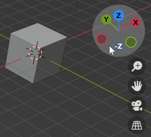 Rotate by pressing and holding the XYZ axes in the image.
You rotate by holding down the scroll button on the mouse, just like in SolidWorks. So that's convenient. There's also a set of XYZ axes in the top right corner that you can grab and rotate like the Autodesk ViewCube. You can also click top, side and front views. Nice. Clicking and holding the little hand button next to the axes moves the center of rotation. And you zoom by scrolling the wheel.
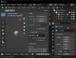
The little camera symbol next to the axes lets you look through the camera that you've put into the scene (you can also press 0 on the number pad). Someone in the Youtube comments mentioned that F12 renders the camera view. So 0 and then F12 is a quick way to render the model. Next to the camera icon is a grid symbol, which switches between orthographic mode (good for modeling) and perspective mode (good for rendering realistic images).
It's good to keep an eye on the status bar on the bottom, which shows you the context you're working in at the moment. Ctrl+Space is a convenient way to maximize any viewport or panel in the interface, and then you can press Ctrl+Space again to return to the default setup:
 Default interface (left) and Ctrl+Space to maximize side panel (right).
There are several tabs at the top that represent different workspaces. In each workspace, the panels in the Blender interface have been set up for that particular task:

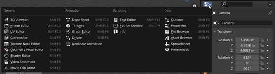
All the viewports and panels can be resized. To choose a different panel, click the symbol with the down arrow in its top left corner:
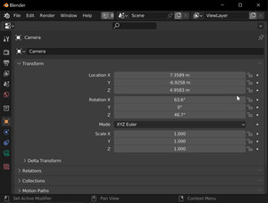
In the Layout workspace, pressing T will open commonly used tools like Move and Scale, and pressing ++N++ will open info about the selected object, tool-specific options and view options.
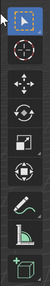
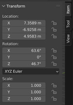 Left menu is toggled with T, right menu is toggled with N.
Notice the little tabs on the right side of the right menu called Item, Tool and View. In the View tab, you can edit the position of the 3D cursor, which acts as the spawning point for new objects and you can do things like pivot objects around it.
In the Layout workspace, the Timeline below the viewport controls the playback of the animation. You can scroll to zoom in and out and hold the scroll wheel to pan. You can define start and end points and add key frames.
Warning
DON'T MAKE TUTORIALS
In our weekly local Fab Academy meeting in Iceland, I mentioned how long the documentation was taking and that I wasn't getting anywhere with Blender. My instructor Þórarinn said that I shouldn't be making a tutorial on how to use Blender but rather summarize what I did, what was interesting and then link to the tutorial that I used. That's a relief. The rest of this page will be more concise and interesting.
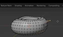
I ended up quitting the official Blender tutorial after the third video and starting the doughnut tutorial by Blender Guru on Youtube. I remember things much better when I have a goal in mind and just use the tools I need to achieve it. I followed videos 1 through 6.
I haven't modeled anything organic before, so it was interesting to try make the doughnut lopsided and kind of realistic. It goes against my engineering training, where you usually want things to be symmetrical. I liked getting to know subdivision modeling, to make smooth object using relatively few polygons. And I really liked that my 3D mouse works in Blender.
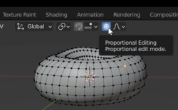
The few times when I've attempted to edit a mesh, I've moved single vertices, resulting in gnarly, pointy looking objects. So I always gave up! But now that I know about proportional editing in Blender, I can select a single vertex and the vertices close to it will follow, while those further away will be affected less. This is much quicker and more effective. I love it! And thinking about my final project, the robot arm, it would be lovely to make a keypoint editor to move it, and use proportional editing to move the keypoints around the moved point, to get a smooth rolloff. I also want to remember the Alt+S shortcut to make the faces move directly outward (normal to the faces).
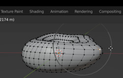
I still have some way to go before I'll be confident in my mesh editing skills. Here's my first attempt to make the icing on the doughnut droop:
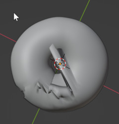 Side view looks good, top view reveals what's actually going on.
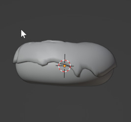
After some backtracking, the icing started to look good by direct editing of the vertices. Next I tried a bit of sculpting. That means using brushes to edit the mesh. I was able to make drops in the icing by sculpting it.
Rendering in Blender
I tried adjusting the camera view and the light to get a good result. I tried bot the Eevee real-time rendering engine and the more realistic, but much slower, Cycles ray-tracing rendering engine. The rendering was quite slow until I enabled the CUDA graphics card in the laptop.
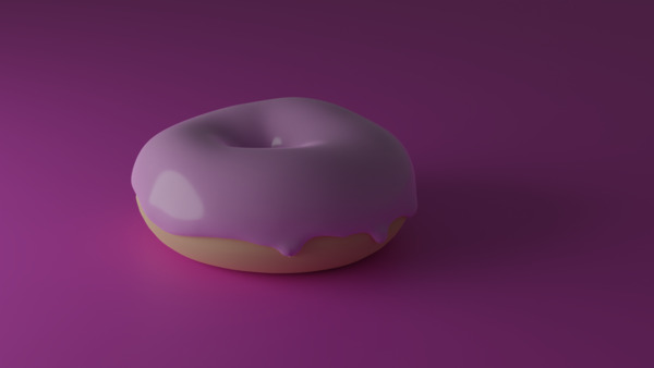 Final result
Design file
The doughnut Blender file is 6.8 MB, so I won't include it here. But I uploaded it to Sketchfab:
Blender simulation
I also went through a really quick tutorial on cloth simulation. Here is the result:
It's fascinating! There are doors opening for me left and right! Blender is a pretty incredible piece of sofware.
Design file
The Blender file is 20.2 MB, so I won't include it here. But I uploaded it to Sketchfab:
You can make your own in ten minutes plus maybe 30 minutes of render time.
2D design in Inkscape
I've started using Inkscape a bit since I started working at Fab Lab Ísafjörður. But I haven't used the Clone tool before. Here's a little experiment with cloning a rectangle:
I didn't save the Inkscape file, it wasn't very interesting.
Antimony modeler
I set up a Raspberry Pi in the case that I need to use Linux during the course. I used this tutorial to enable cloud connection. That way I can connect to the Raspberry Pi from outside its network. When I connected remotely for the first time, the screen resolution was tiny because the Raspberry Pi wasn't connected to a monitor. I followed this tutorial to hardcode the screen resolution into the boot config text file.
I tried to build Matt Keeter's Antimony modeler on the Raspberry Pi, but without luck.
Failure
sudo apt install git build-essential libpng-dev python3-dev libboost-all-dev libgl1-mesa-dev lemon flex qt5-default ninja-build cmake
Reading package lists... Done
Building dependency tree... Done
Reading state information... Done
Package qt5-default is not available, but is referred to by another package.
This may mean that the package is missing, has been obsoleted, or
is only available from another source
E: Package 'qt5-default' has no installation candidate
I tried to install qt5 instead of qt5-default, but it didn't work.
Failure
I don't know where to go from there.
Update after Fab Academy
I installed Linux Mint in a virtual machine using VirtualBox, which was really easy. When browsing the software manager I came across Antimony, already built and ready for download! I tried a few operations and connected them together using the node view. I always find node software like this intimidating, but it didn't take long for it to become intuitive. Here's what I made:
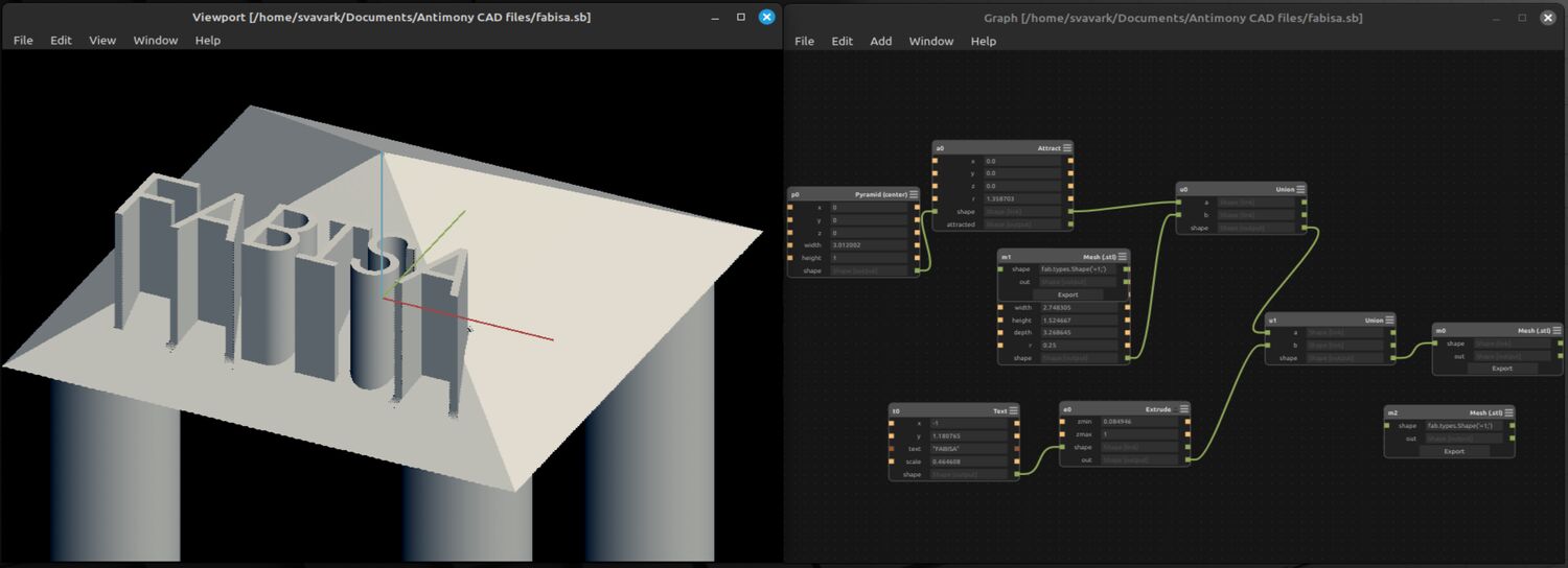 Simple test where I combined features.
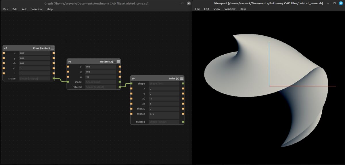 You can easily do things that are hard in other CAD software. Here I made a cone, rotated it and put a twist on it.
I'd like to 3D print these models. I tried to move the files from the virtual machine to my Windows 10 desktop but the drag and drop feature didn't work. I also tried setting up a shared folder between the two operating systems, which appeared in Windows but I couldn't see it in Linux Mint.
I find it really cool that the world's most advanced 3D printed rocket nozzles are being designed in CAD software that's based on Matt Keeter's geometry kernel.
Antimony in Windows
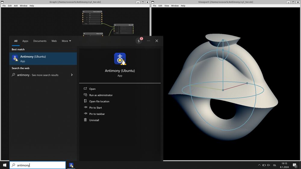
I set up the Windows Subsystem for Linux. Now I have Ubuntu running inside Windows at near-native speed. I installed Antimony inside WSL and now I can open this unusual Linux-based CAD program from the Windows Start menu. From an free software perspective the WSL is kind of grotesque, but it's just so convenient. Here's how you can do it:
You need WSL2 to run Linux apps with a graphical user interface. Here are the instructions that I followed to set up WSL2. It's super simple if you have a recent enough version of Windows, just open up Command Prompt by opening the Start menu and typing cmd, and then type in:
After a few minutes the Windows Subsystem for Linux is installed on your machine and you can open the Ubuntu terminal.
After a bit of searching I found this page, which told me how to install Antimony on Ubuntu 22.04 using the Debian apt package manager. Open the Start menu in Windows and type Ubuntu to get the Ubuntu terminal running. This is what you put into the Ubuntu terminal to install Antimony:
That's it! Now you can open Antimony like a Windows app and play around with it any time!
Kokopelli modeler
I also tried to build Matt Keeter's Kokopelli from source on the Raspberry Pi, but also without luck:
Failure
sudo apt-get install python python-dev python-pip gcc g++ libpng12-dev make bash cmake
Reading package lists... Done
Building dependency tree... Done
Reading state information... Done
Note, selecting 'python-is-python2' instead of 'python'
Note, selecting 'python-dev-is-python2' instead of 'python-dev'
Package libpng12-dev is not available, but is referred to by another package.
his may mean that the package is missing, has been obsoleted, or
is only available from another source

Package python-pip is not available, but is referred to by another package.
This may mean that the package is missing, has been obsoleted, or
is only available from another source
However the following packages replace it:
  python3-pip

E: Package 'python-pip' has no installation candidate
E: Package 'libpng12-dev' has no installation candidate
Voxel modeling
I tried the MagicaVoxel program without looking at a tutorial, and made this figure:
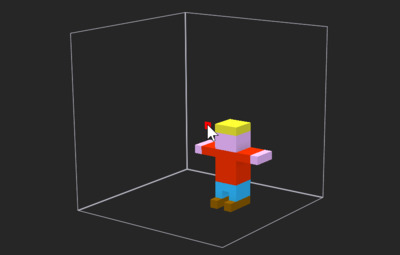
I'm not sure how to make anything useful with this modeling method. Maybe I'll think of something later.
Design file
Here's the voxel guy I made:
Solvespace parametric 3D CAD
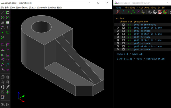
I went through a Solvespace tutorial and quite liked the experience. I like the dark 8-bit look of it. I was also surprised to find that my 3D mouse works in Solvespace. The program is lightweight and modeling seems quick, once you've memorized a few keyboard shortcuts and familiarized yourself with how the sketch constraints work. In the time that it took Fusion 360 to open, I saved the bracket and exported it as STEP, STL and a triangle mesh with a Three.js html viewer. You can open the 3D model in the browser below!
Open bracket 3D model in browser
Solvespace was written by Jonathan Westhues and he's made other impressive things too. This tube joint pattern generator would have been a lifesaver when we were building the steel tube spaceframe for the first and second Team Spark electric racing cars back in 2011 and 2012. Solvespace was maintained for a few years by M-Labs. M-Labs wrote the Three.js export feature, among others. Jonathan says himself that Solvespace's NURBS operations are not as good as OpenCASCADE's but they're much smaller. The constraint solver is a remarkable achievement though, and it works well. Jonathan originally made a 2D CAD program which was superseded by Solvespace, but the paper he wrote on the sketch solver is an interesting read. The Solvespace solver library is the solver behind CAD Sketcher in Blender. The Solvespace feature list mentions G-code export with cutter radius compensation and path traced with mechanism, exportable into a spreadsheet. These two are interesting. The next thing I want to try in Solvespace is to make a movable assembly.
For me the killer feature in Solvespace is the Three.js export. The in-browser Three.js model even has the Solvespace look! The file includes the whole Three.js library, which means that the file for this simple bracket is 0.7 MB. So if you want to display more than one model they will take up a lot of space. In that case you may want to export only the js model geometries from Solvespace and then manually link them to the three.js file. The bracket model geometry is only 52 KB.
Design file
Here's the Solvespace model for download:
Rhino3D
Rhino can do pretty much everything. A full license costs a thousand euros and you keep that version of Rhino for life. Even better, students and educators can get a license for 200 euros. But first, I'm going to get the trial version, which lasts for 90 days (all of the Fab Academy). I've wanted to try Rhino for quite some time, but all those unfamiliar tools and menus are a bit intimidating. I know solid extrude must be there, but where?
I didn't like the official Getting Started tutorials very much, because the first videos just show you things but not making you do anything in the software. So I went to Youtube and found a 40 minute introduction to Rhino for architecture students. I followed along for 17 minutes.
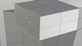
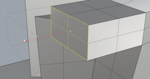 Selecting a surface with Ctrl+Shift left mouse in the first image and dragging the black dot on the red axis. That leads to the extrusion in the second image.
I learned to make lines, curves, surfaces, solids and how to manipulate them.Now that I've turned on the Gumball tool, I can just select a surface and extrude it by pulling on the dot on one of the Gumball tool axes. Nice!

In the above picture I'm rotating a surface, which changes the whole shape.
Rhino seems to have many more tools than Fusion 360, so it's interesting for making complicated shapes. I especially like the ability to grab any point, line or surface and move and rotate them with the Gumball tool. That's a really quick way to make interesting shapes that I would find difficult to model in Fusion 360. But I still haven't learned how to model precise things in Rhino with dimensions and constraints.
Design file
Here's the Rhino file I made (it's just nonsense like you see in the images):
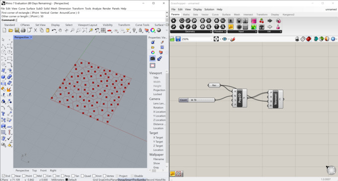
Rhino + Grasshopper
I went through a quick tutorial and made a nice Voronoi pattern! I really like the possibilities in Grasshopper. I've wanted to try it for some time. And I like the simplicity of the Voronoi method, you just make a line midway between every point and its next neighbor, and then trim the lines. A random distribution of points results in a cellular-like pattern.
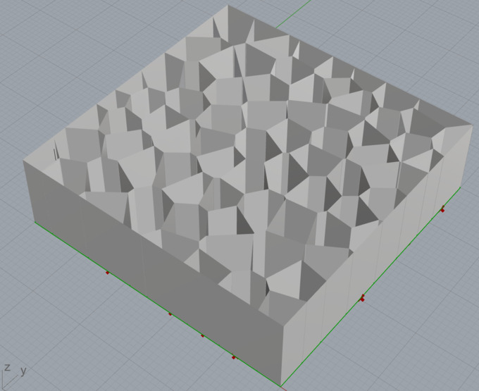
Design file
Here's the Rhino file with the extruded Voronoi surface.:
Download Rhino + Grasshopper Voronoi model
FreeCAD
After watching this video, I got excited about learning FreeCAD, but I'm 20 minutes in to a tutorial and I've only learned how to enable dark mode, and I've discovered that my 3D mouse doesn't work well with the program. Or maybe I haven't found the right settings.
Update: Now I've started modeling and I'm starting to like FreeCAD. It's incredibly capable. I only stuck with it because Neil Gershenfeld is so adamant that it's a good tool and that his Fab Academy students should try it.
 The feature tree is very similar to Inventor and SolidWorks. You can go back in time and change features that control features later in the tree. I could get used to this.
Hold on! There's an HTML export option! And it uses native WebGL, without the Three.js library on top of it. And the bracket model is a tiny 60 KB, including the viewer! Look!
Open FreeCAD bracket in browser
The HTML file is human-readable, so I could easily go into it and change the background gradient colors. The bracket itself still has a yellowish color on the bottom, but this is good enough for now.
Open FreeCAD bracket with greytone background
Design files
Here's the FreeCAD bracket model:
Download FreeCAD bracket model
Update: I also tried setting up a parametric model based on a spreadsheet. I followed this tutorial.
Here's the model that includes a few configurations:
Download configurable FreeCAD cube
I would also like to try Python scripting in FreeCAD when I have the time.
On free and open source engineering software
I must admit that I've been prejudiced against free and open source versions of the engineering software that I've been using. If it's free there must be something wrong with it. I've assumed that it must be missing lots of features and that it must have a bad user interface and be riddled with bugs. Not so! And there are features in the free software that are not found in paid software at any price. Autodesk and Dassault Systémes, the makers of the CAD software I use most, have thousands of employees. FreeCAD is developed by like three people and it can do finite element analysis! How is this possible? Because of the ecosystem of open-source packages that get integrated into FreeCAD, like the Open SCAD workbench, for example. And the open nature of the software ensures that those who are interested can learn everything about it, down to the lowest level, and improve it and make their own versions of it. This is similar to the original purpose of published patents, to disseminate technology for everyone.
It's interesting to note that an old open source project that was developed in the late 1960s is still the state of the art in structural Finite Element Analysis. Nastran is a million lines of FORTRAN code written for NASA by the company that would become MSC. Nastran is the core in the most advanced FEA solvers in Autodesk Inventor and even in more exotic and cutting-edge software like ADINA, which is used for the most difficult multiphysics problems like simulating nuclear reactors before they are built. I came across ADINA in my quest to understand shock absorbers. They are surprisingly complex. ADINA makes an FEA solver that is more advanced than the Siemens NX solver, and that is saying something. NX is arguably the most advanced CAD software in the world. Its geometry kernel is also the basis of the Onshape, Shapr3D and Altair CAD software.
CADtron
I didn't try Kevin Lynagh's CADtron because it hasn't been released yet, but it's an interesting gesture-based 2D CAD program based on the Solvespace library. Here's an example of a perpendicular constraint drawn with a stylus (from Kevin's video):
Fusion 360
Final project mockup
I made a mockup of my final project in Fusion 360. I connected the parts together with joints, so that I could move the arm realistically. This arm has six axes. I imported a few electronic components from GrabCAD and put them on the arm to show how I envision the design.
I want to make the arm out of printed circuit boards. The are fiber reinforced, so they are quite stiff. If I place some rigid foam between two circuit boards I have a very stiff and light part that also contains the microcontroller and motor driver to control the joint. I haven't seen a robot arm made of PCBs anywhere, so that's what I want to make.
My instructor Þórarinn suggested that I think about designing the arm in such a way that it could also be laser cut or 3D printed, depending on the fabrication tools that people have access to. So here are three versions, rendered in the Fusion 360 rendering environment:
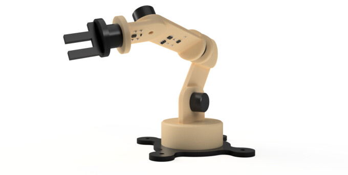 Tan colored FR1 circuit board arm
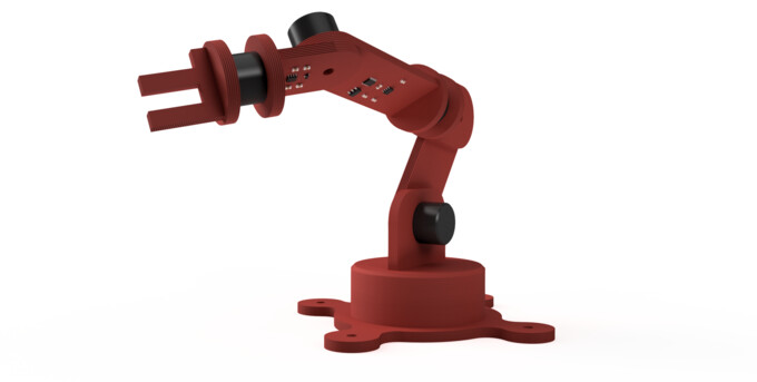 Red 3D printed arm
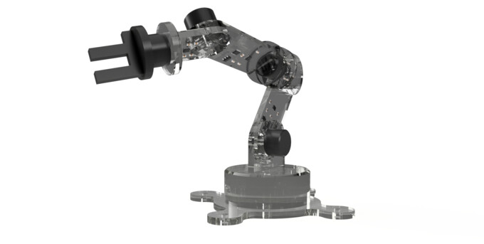 Transparent acrylic laser cut arm
Motion study
I had trouble figuring out the Fusion 360 Animation environment, so I did a motion study instead.
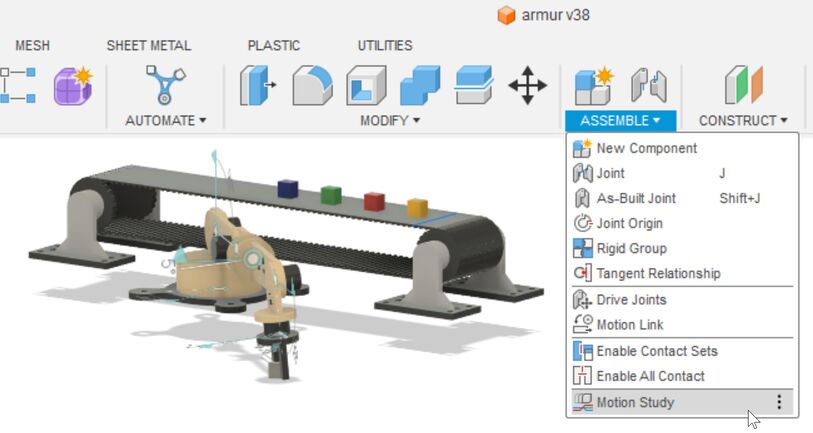 Before making the motion study, I needed to create rotational joints between the parts using the Joint operation (see in the menu above).
OK, let's go back and define all the joints first, and make the base fixed to the ground, so that it doesn't rotate with the other parts.
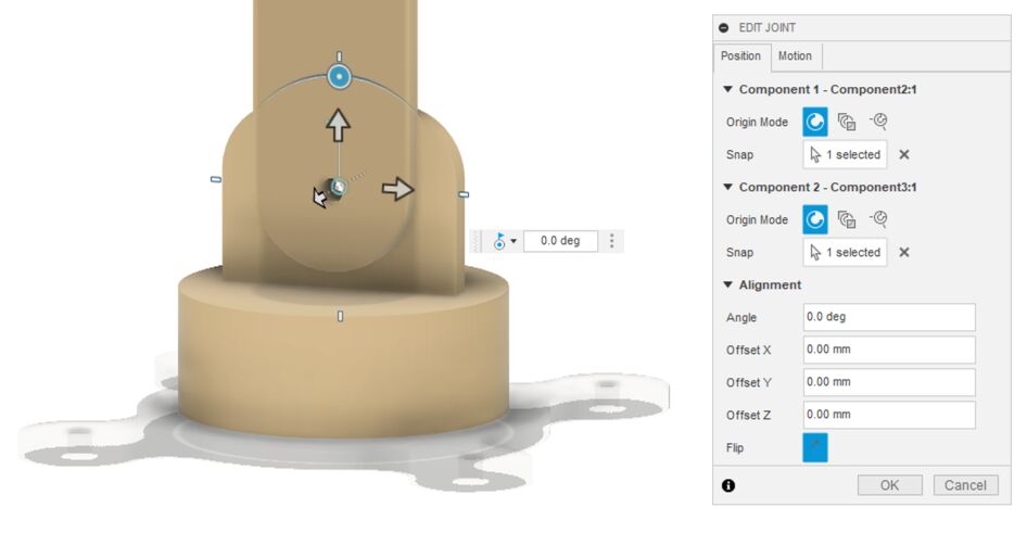 It's quite simple to select the hole on each part to rotate around and that's it, really. You may need to play around with some of the settings until you get what you want. But there aren't that many settings.
 All the joints that I defined automatically appear in the motion study as a colored line. I can place keypoints on those lines at certain times to create motion in those joints. Then it's just a matter of figuring out which joint is which and its extents of motion and playing around with the interface until the movement looks good.
Note
To capture short animated GIFs of what I'm doing in software, I use LICEcap. It's available for Windows and MacOS. It's lightweight and produces much smaller GIFs than any other screen capture program that I've used.
Because of this recommendation, I used the command line tool Gifsicle to resize the GIF after recording it with LICECap. I tried double-clicking gifsicle.exe, but nothing happened. I found this Reddit discussion, where it was explained that Gifsicle is a command-line tool, so you just enter the commands. But where? I tried the same method as with ImageMagick. I put the GIF into the folder with Gifsicle and typed cmd Enter, which opened the Command Prompt in that folder. Then I ended up using the command
I quite like the control interface for the motion study. Each line controls a joint. You click the line to make a keypoint and enter the position of that joint. This is more intuitive than the robot control software that I've tried. It would be nice to control the arm in this way. Someone on the internet said that Fusion 360 is not the right tool to control robot arms, and they're probably right. They recommended Blender. I've been thinking about writing a Python script for Blender that uses the animation environment to control my robot arm. Or I could try a browser-based solution. I saw something like this when searching the Fab Academy archives.
Design file
Here's the robot arm Fusion 360 file, including the conveyor belt and motion study: