Embedded Programming 
Assignment
Individual assignment
- Browse through the data sheet for your microcontroller
- Write program for a microcontroller development board
- to interact (with local input &/or output devices)
- and communicate (with remote wired or wireless devices)
- extra credit: use different languages &/or development environments
- extra credit: connect external components to the board
Group assignment
- Compare the performance and development workflows for other architectures
See more info and recording of the lecture here.
The RP2040 datasheet
I read the Raspberry Pi RP2040 datasheet loosely. This is one of the more interesting microcontrollers to me, because of the flexible Programmable Input/Output (PIO), two fast cores and you can program it in the Arduino IDE or in the friendly Python language. The datasheet also looks friendlier than datasheets for other microcontrollers. Still, that may only be the graphic design, because the actual content is cryptic. I understood like 0.5% of what I read.
But I did pick up some interesting tidbits. The RP2040 has a built-in Real Time Clock. That would be useful for my wake-up mask. It has a dormant state which uses almost no power and it can be woken up by the RTC. That also sounds good for the wake-up mask. But in that case, the RTC needs to use an external clock source, which can be as slow as 1 Hz. Hold on, the RTC needs an external crystal. That's good to know. I thought you didn't need to add a crystal, but the only truly internally generated clock is the Ring Oscillator. Its speed varies with process, voltage and temperature, so it can't be used for RTC, USB communication or analog to digital conversion.
When reading the RP2040 datasheet and testing the Xiao RP2040, I wondered: Does the tiny Xiao board have a crystal? I don't see one on the board. Is it underneath the metal cover with the RP2040? If it doesn't have an external oscillator, then the Real Time Clock doesn't work and I can't use it in my wake-up mask. I looked around and found the schematic for the Xiao RP2040 and there is a crystal and Flash memory. Good. They must be underneath the cover.
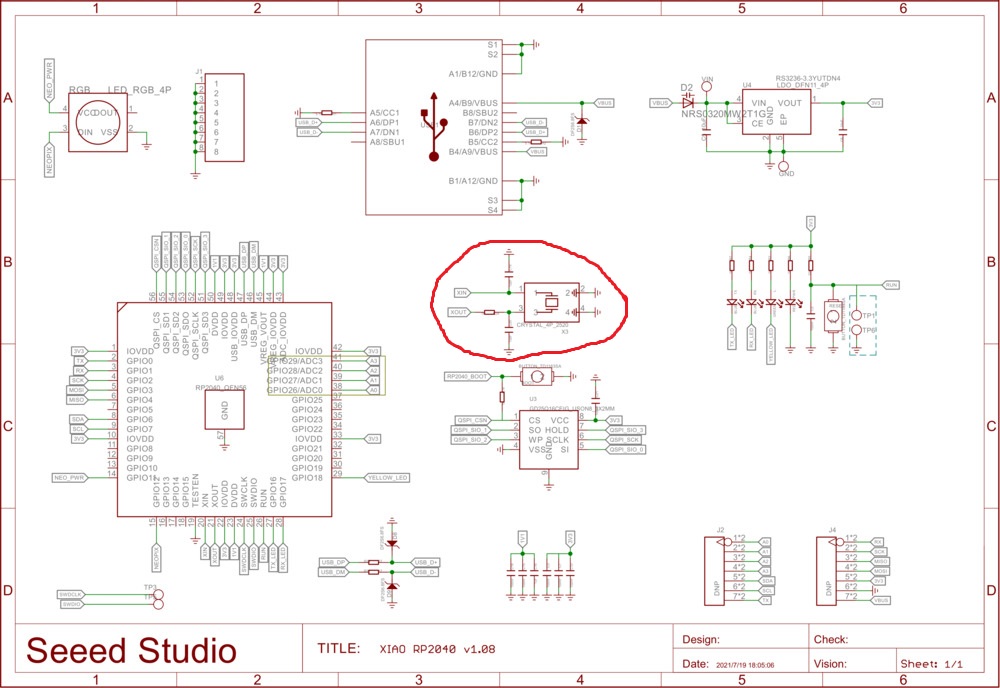 So there is a crystal.
But maybe the internal RTC in the RP2040 isn't good enough and I need to use something like the DS3231 chip.
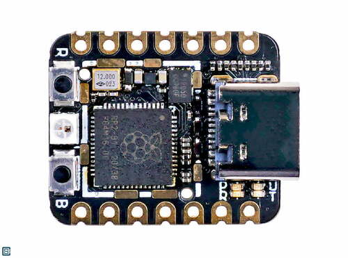
Update: My instructor Þórarinn showed me a picture of what's underneath the metal cover. The picture was actually on the same page as the schematic that I had found, but I hadn't looked at the whole page. So here it is, and you can see the crystal marked with 12.000:
I watched a video that stated that computers are horrible at division. So I was glad to see that the Raspberry Pi Foundation decided to implement a hardware division unit in the RP2040. I wondered why there was no hardware multiplier until I got to the section about the Arm Cortex M0+ cores inside the RP2040. The Arm specification has hardware multiplication built in.
I watched another video that shows how you can easily overclock the Raspberry Pi Pico. Overclocking has always sounded to me as if you're going to overheat the device and damage it, or make it unstable, but the datasheet says that overclocking processors in general is usually fine. In the video, a maximum speed of 250 MHz is recommended.
I was interested in the example programs provided under the Programmer's Model headings in the datasheet but I have no idea where to put them or how to run them. There are also lots of tables with registers and commands and stuff like that but I can make neither heads nor tails of them. What are they? What would I do with them? The mysteries continue.
The RP2040 chip has 36 General Purpose Input/Output pins. That's quite a lot. Typically, a few of those pins are connected to an external flash memory chip, as in the Raspberry Pi Pico board. The Pi Pico board has 26 user-accessible pins. Three of them can be used for reading analog signals and converting them to digital numbers. The ADCs are officially 12 bit but the effective resolution is I think something like 10 bits because of an error in the chip design.
The RP2040 has plenty of communication interfaces (SPI, UART, I2C, USB), and if you need something else, you can make it yourself with the Programmable IO blocks. It has eight two channel PWM generators (they're called slices). So can it generate 8 PWM signals, or 16? The PIO machines can always see the states of all pins. That's interesting. I think I remember reading that the DMA channels share a similar view.
My Master's thesis advisor said that when programming in C, you get much more access to all the computer's devices and peripherals. When the University stopped paying the license for his vibration meter, he wrote a driver for it in C. That sounds like wizardry to me, and more than a little fascinating. But the C code examples in the RP2040 datasheet don't look fun to me.
PIO
This is the most interesting part, the Programmable IO. There are two PIO blocks in the RP2040 and each has four state machines. That means that you have eight simple, deterministic and precisely timed cores that are specialized for input and output. Each state machine has two 32 bit shift registers. Jakob Einar, a frequent guest at Fab Lab Ísafjörður, made a cnc plotter using old DVD drives. He said that a shift register enables a slow Arduino Uno to control all the steppers in sync. I'm curious about how a shift register works.
There are two PIO blocks with four state machines each. Each state machine has:
- Two 32-bit shift registers (I need to find out what they do)
- Two 32-bit scratch registers (you can think of them as variables, they're called x and y)
- 4x32-bit bus FIFO in each direction or 8x32 in a single direction (data flows in and out using these and gets stored in the two variables x and y)
- Fractional clock divider (if you want the PIO to run slower than the main clock speed)
- DMA interface (to get lots of data from memory without using the processor, or put data into memory)
- IRQ flag set/clear/status (I think this is to alert the main processor that the PIO has finished an operation)
The state machine has only nine instructions: JMP, WAIT, IN, OUT, PUSH, PULL, MOV, IRQ AND SET. Each instruction takes exactly one cycle. It's interesting to try programming at this level. I like the fact that the first three bits of each instruction is like this: JMP: 001, WAIT: 010 and so on. I understand that labeling system!
Precise timing is what microcontrollers are good at! You can get PIO programs from the Raspberry Pi Pico PIO library, you can write them yourself or (and this is the most interesting case) you can generate them programmatically. I wouldn't know how to do that, though. All the supplied code examples are written in C. This may be a good introduction. I'm putting this here for myself to discover later. Here's some more stuff.
I did find one example of using DMA in MicroPython code. The iosoft blog says that MicroPython doesn't have built-in functions to support DMA and doesn't provide a simple way to access the ADC, DMA and I/O pin registers. But there is a way to define these registers using the obscure uctypes. And then you need to be familiar with the RP2040 datasheet. Here someone has written some code based on the iosoft blog. This should be easy to try out, because it's Python code. Here's a resource with good pictures that goes into PIO + DMA.
Most instructions are executed from the instruction memory, but there are a few other sources. The most versatile of these is the OUT EXEC instruction. You can use this to embed instructions in the data stream passing through the FIFO.
I didn't understand the Wikipedia entry on shift registers. The Sparkfun article says that they're used to add more I/O pins to a microcontrollers. But that's not what's happening in the PIO. Apparently, you load one bit into the shift register at a time (a 1 or a 0). When a new bit enters, all the bits inside the shift register are shifted to make room for it. Then you can use the latch pin to output all the bits at the same time from the shift register. So you're turning a serial port into a parallel port. I guess this is useful for synchronized CNC movements, but how does it work inside the PIO block in the RP2040?
The output of the PIO assembler is shown, and it consists of hexadecimal numbers. They look scary and incomprehensible. I noticed that they all have an x in them, so I asked Google why hexadecimal numbers all start with 0x. Turns out it's just to let the parser know that it's a hexadecimal base number instead of other bases.
I've seen a lot of definitions and explanations, but what I really need is an example that I can run. I still don't understand how the data flows and how the operations are carried out. To see what's going on inside the chip, I probably need something like PicoReg. It's a debugger for the Raspberry Pi Pico. The advantage is that it's written entirely in Python I can set it up on a Raspberry Pi. I can wrap my head around that.
I'd like to try to implement a PIO+DMA stepper controller with acceleration ramping. But I likely won't have time for that this week. V. Hunter Adams at Cornell has implemented it, but to use it you need to set up a toolchain for C. This forum post is also interesting. cleverca22's comment on this post may also hold clues. Seemingly unrelated, but there may also be some clues in the servo easing algorithm. There are stepper control PIO programs here and here. But they don't implement ramping. And again, you need to use the C/C++ SDK. The RP2040 datasheet says that if you want to get started with PIO, a walkthrough of writing your first PIO program is in the Pico C/C++ SDK. It also covers using PIO with DMA. But I want to use Python. Or at least I want to be able to make a library for Python. Is it possible to do that in C/C++? Yes. But if you build an external C module for MicroPython, you have to build your own MicroPython firmware to put on the RP2040. There's another possibility, which I like better:
An alternative approach is to use Native machine code in .mpy files which allows writing custom C code that is placed in a .mpy file, which can be imported dynamically in to a running MicroPython system without the need to recompile the main firmware.
I flipped quickly through all the communications protocols but read PWM more carefully. If I will use brushless motors in my robot arm, I need to get to know Pulse Width Modulation. It's interesting how flexible the pin mapping on the RP2040 is, the PWM slices can use any of the GPIO pins, and so can PIO. I actually understood a part of the description of how a PWM slice works. It's a 16-bit counter that the wraps back to zero. Wrap is a command in pioasm that enables you to jump back to the beginning without using a JMP command, and it takes 0 cycles. I'm beginning to understand a little bit, even if I can't use these things yet. I guess I could DMA to push a sine wave from a lookup table to three PWM outputs to control a three-phase brushless motor. Then the main processors would be free to do other tasks. This arbitrary wave generator using PIO and DMA may be worth taking a look at when I have some time.
There's a lot going on inside this $1 chip. It's like a whole city, complete with different neighborhoods connected together with highways and smaller roads to move data between places.
All roads lead to the C/C++ SDK, it seems. Here are community libraries for the SDK. There are also lots of examples in the Raspberry Pi GitHub repo. I will have to jump in at some point.
One question remains: What is the OSR?
There is a bit of programmer humor in the datasheet, on page 359 it says that I2C is an ubiquitous serial bus first described in the Dead Sea Scrolls, and later used by Philips Semiconductor. On page 364 it is conjectured that the PIO can run DOOM with a high enough clock speed. On page 365 it says that a full 32-bit addition takes the PIO only around one minute at 125 MHz. What? So using the PIO for mathematical operations takes hundreds of millions of cycles?
DMA
Direct Memory Access is the other interesting feature in the RP2040. It's a memory controller that can copy data from one place to another very fast without the processor's intervention. Throughout the RP2040 datasheet there are mentions that this and that part of the chip has a DMA interface. It looks like it's important to learn to use DMA if you want to make things run fast. Could DMA be used to feed a PIO state machine with acceleration ramps for a stepper? I would like to learn a little bit about how DMA works and how to set it up, but it seems that it's not possible in MicroPython. The Raspberry Pi Pico C/C++ SDK instructions mention that you can use DMA by including a library called hardware_dma. Setting up a C/C++ toolchain sounds intimidating, but maybe I have to do it if I want to try using DMA. I think DMA programming is too complicated to get into for now.
ADC
The Analog to Digital Converter takes 96 clock cycles to make a 12-bit measurement. That's good to know. The RP2040 ADC has a few errors, most notably that the quantization error looks like a sawtooth. Also, because the wrong size of capacitor was used in one part of the ADC, there are big spikes in differential non-linearity. I won't pretend to know what that is, but it means that there will be spikes in the measured values in four places. The scaling factor for the internal temperature sensor is specified here in the datasheet. You can see it an example code in the Chip temperature section below.
I looked at the Raspberry Pi Pico Python SDK and found it a bit thin. I also skimmed Getting started with Raspberry Pi Pico, which shows how to set up a C/C++ programming environment for the Pi Pico, and it looks extremely complicated. But that's where the juicy stuff is.
Programming the Xiao RP2040
The Xiao RP2040 has a reset button, so it's more convenient to use in that respect than the Raspberry Pi Pico.
Hello RP2040
I tried Neil Gershenfeld's Hello RP2040 Python program:
I like having an RGB LED to play with. It could serve as a simple interface for the wake-up mask or the robot arm if I assign a different meaning to every color.
Chip temperature
I did this one with the Raspberry Pi Pico. Setup and programming is identical to the Xiao RP2040. I found a nice tutorial on using the temperature sensor which is built into the RP2040 chip. It's useful to make sure that the chip doesn't overheat, but it's also a good exercise in measuring an analog voltage. Since I've tried blinking the onboard LED already, I'm going to use that knowledge to modify this program to turn on the LED when the temperature crosses a threshold:
from machine import ADC, Pin
import time
led = machine.Pin("LED", machine.Pin.OUT)
adc = machine.ADC(4)
while True:
    ADC_voltage = adc.read_u16() * (3.3 / (65535))
    temperature = 27 - (ADC_voltage - 0.706)/0.001721
    print("Temperature: {}°C".format(temperature))

    if temperature > 26:
        led.value(1)
    else:
        led.value(0)

    time.sleep_ms(100)
I added the if statement and removed the temperature in Fahrenheit. You can see that you need to scale the analog measurement to get the temperature in degrees Celsius. I suspect that that every chip will give a slightly different value because of manufacturing variability. So it might be better to measure the temperature with a better sensor and put that value into the scaling factor. But since this sensor isn't meant to be super precise, we'll let it be.
Interfacing with LCD screen
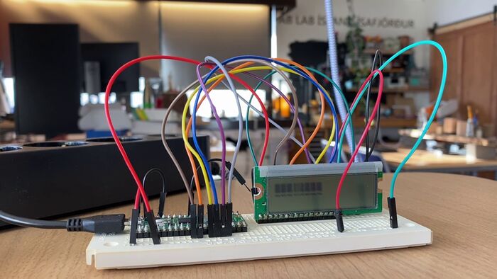
I connected a classic 16x2 character LCD screen to the Raspberry Pi Pico, but it didn't work. I needed to use the 4-bit mode (where you connect the LCD directly to the microcontroller) because I didn't have an LCD driver chip. Aby Michael's Fab Academy site had a useful diagram with the LCD pins. The ElectronicWings diagram was even more useful. After some Googling I found that the screen needs 5V signals. The RP2040 is a 3.3V chip, so that's why I'm getting glitchy results. Its strange that it worked with a Pico in the tutorial that I used (click the link in the video description for a connection diagram). I'd like to try the small OLED screen that is in the Fab Lab inventory next. That one is 3-5V tolerant, and much smaller and versatile than the 16x2. And it only needs four pins. Look at that nest of wires above! The OLED will be a great improvement.
Here are the files I used, you just open each of them in Thonny and save them to your Pico. The main.py file runs automatically when you power the Pico on. The other two are a library for interfacing with the LCD. Beware, this didn't work for me.
Interfacing with OLED screen
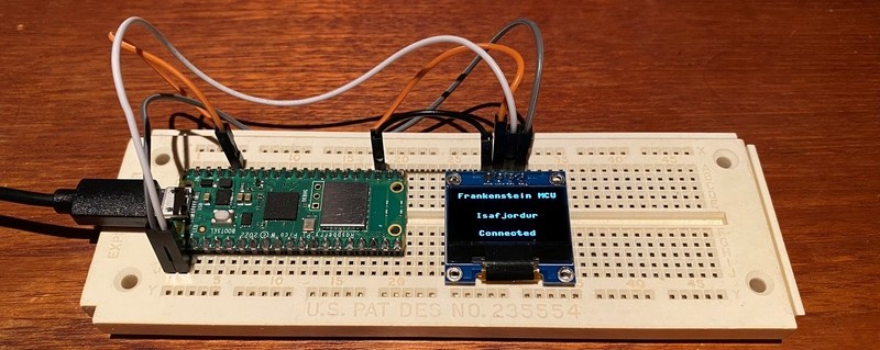
I used Kevin McAleer's simple code example for the SSD1306 OLED screen. It just writes Test 1 to the screen. It was exhilarating to see the tiny letters light up on the screen on the first try! I then changed the text to something more useful, a prototype display for the Frankenstein MCU, which Fran and my instructor Þórarinn are working on. The plan is to make a WiFi connected button in every Fab Lab and the staff push the button every day to show that the lab is active. The connections between labs appear on a spinning globe made in Three.js, which runs in the browser.
Stepper control with RP2040
This one I also did with the Raspberry Pi Pico.
from machine import Pin
from time import sleep

IN1 = Pin(2,Pin.OUT)
IN2 = Pin(3,Pin.OUT)
IN3 = Pin(4,Pin.OUT)
IN4 = Pin(5,Pin.OUT)

pins = [IN1, IN2, IN3, IN4]

sequence = [[1,0,0,0],[0,1,0,0],[0,0,1,0],[0,0,0,1]]

while True:
    for step in sequence:
        for i in range(len(pins)):
            pins[i].value(step[i])
            sleep(0.01)
Controlling the stepper is surprisingly simple. It has four phases, so you connect it to four pins on the Pico. Then you just alternate which pin is HIGH while the others are low. The stepper motor has 64 steps per rotation, but it also has a 1/64 gearing ratio, so in total it has 64 * 64 = 4096 steps per rotation. That's pretty good for a 3 dollar stepper! I bought a set of five 28-BYJ-48 steppers with ULN2003 drivers for $15. They're cheap and precise!
But there are two drawbacks. They're quite weak. For a motor with 1:64 gearing, it's surprisingly easy to make it skip steps. Also, the gearbox introduces backlash which is much bigger than the step size. The step size is 0.09° but the backlash seems to be a few degrees. Maybe it's possible to correct for the slop in software every time the motor changes direction. But that won't work 100% and definitely not with small motions. I wonder if these motors are a good fit for my robot arm.
In the video above I changed the sleep value and then ran the program. First it was 0.1 s, then 0.01 s and finally 0.001 s. When I went below 0.01 s, the stepper stalled. It's fun to have status LEDs on all the phases. At slow speeds you can see how the phases are turned on and off. I want to have status LEDS on every output pin on every microcontroller board! It's a really handy debugging tool. I laser cut a press-fit acrylic arrow to see the motor's movement better.
Since I have the 12V version of the 28BYJ-48 motors, I can run them on a 9V battery. So here's my first foray into battery-powered electronics. The Pico is still powered by a USB cable, though. I need to learn how to make a 5V regulator board, so that I can also power the Pico using the 9V battery.
PIO stepper control
I followed a tutorial and wrote a program that controls a stepper with PIO, without using the processor at all. I then modified it to include four PIO state machines that run the same program but are clocked at different frequencies:
Here's the code:
from machine import Pin
from rp2 import PIO, StateMachine, asm_pio
from time import sleep
import sys

@asm_pio(set_init=(PIO.OUT_LOW,) * 4)
def prog():
        wrap_target()
        set(pins, 8) [31] #8
        nop() [31]
        nop() [31]
        nop() [31]
        nop() [31]
        nop() [31]
        nop() [31]
        set(pins, 4) [31] #4
        nop() [31]
        nop() [31]
        nop() [31]
        nop() [31]
        nop() [31]
        nop() [31]
        set(pins, 2) [31] #2
        nop() [31]
        nop() [31]
        nop() [31]
        nop() [31]
        nop() [31]
        nop() [31]
        set(pins, 1) [31] #1
        nop() [31]
        nop() [31]
        nop() [31]
        nop() [31]
        nop() [31]
        nop() [31]
        wrap()

sm0 = StateMachine(0, prog, freq=100000, set_base=Pin(2))
sm1 = StateMachine(1, prog, freq=50000, set_base=Pin(6))
sm2 = StateMachine(2, prog, freq=25000, set_base=Pin(10))
sm3 = StateMachine(3, prog, freq=12500, set_base=Pin(18))

sm0.active(1)
sm1.active(1)
sm2.active(1)
sm3.active(1)
sleep(5)
sm0.active(0)
sm1.active(0)
sm2.active(0)
sm3.active(0)
sm0.exec("set(pins,0)")
sm1.exec("set(pins,0)")
sm2.exec("set(pins,0)")
sm3.exec("set(pins,0)")
nop() is no operation, and you can optionally add a delay after every command, like this: [1]. That was a delay of one clock cycle. I think 31 cycles is the maximum.
Adding a Reset button
The Raspberry Pi Pico has no reset button, but it resets if you connect the RUN pin to ground. So I just connected a jumper to the RUN pin on the breadboard and make the other end of the jumper touch the GND pin that is one pin over to reset the Pico. That's more convenient than unplugging the USB cable and plugging it in again.
Overclocking the RP2040
I tried Chris DeHut's RP2040 overclocking video. He has lots of good stuff about the Pico. Here's his program which changes the clock speed a few times and measures the time it takes to do 100.000 sets of the calculations in the Do_Stuff function:
'''
PICO default clock speed is 125 MHz
Demo to show time to make a bunch of basic math calculations
at varaious clock speeds that the PICO can handle
'''
import machine
import time
import machine

led_onboard = machine.Pin(25, machine.Pin.OUT)

def Do_Stuff():
    st = time.ticks_ms()
    Y = 0
    while Y < 100000:
        Y += 1
        Z = 57
        Z1 = Z + Y
        Z2 = Z - Y
        Z3 = Z * (Z + Y)
        #print(Y, Z1, Z2, Z3)
    led_onboard.value(0)
    #print(Y)
    et = time.ticks_ms()
    #print(et, st, et-st)
    return et-st


cntr = 0
while cntr < 2:    #run whole test several times for observation
    cntr += 1

    machine.freq(125000000)  #set clock to 125 MHz
    x = machine.freq()
    t = Do_Stuff()
    print("\n@", x, " time to run =", t, "ms")


    machine.freq(140000000)   #set clock to 140 MHz
    x = machine.freq()
    t = Do_Stuff()
    print("\n@ ", x, " time to run =", t, "ms")


    machine.freq(200000000)  #set clock to 200 MHz
    x = machine.freq()
    t = Do_Stuff()
    print("\n@ ", x, " time to run =", t, "ms")

    machine.freq(250000000)  #set clock to 250 MHz
    x = machine.freq()
    t = Do_Stuff()
    print("\n@ ", x, " time to run =", t, "ms")

machine.freq(125000000)  #set clock to 125 MHz to clean things up
print("\n All Done Folks!")
The loop runs a few times so that you can take the average of the time measurements. This is one set of measurements:
@ 125000000  time to run = 1167 ms

@  140000000  time to run = 1042 ms

@  200000000  time to run = 729 ms

@  250000000  time to run = 583 ms
That's a big difference by varying the clock speed, and the RP2040 datasheet says that overclocking is usually safe. I will keep this in mind when my programs are running slowly. Then I tried going a bit higher. It worked at 280 MHz, but at 290 or 300 MHz, I got no response from the microcontroller. So this is the best time:
I think I will not go above 250 MHz. That's a lot, twice as fast as the standard RP2040 with a 12 MHz crystal, like in the Pico and the Xiao RP2040. There are instructions online on how to go up to 420 MHz and there is at least one commercial board that runs the RP2040 at 400 MHz.
Custom performance test
I modified the PIO program to control four steppers at different speeds, by modifying the clock dividers in each of the state machines. The state machines all run the same program. It works, and there should be no load on the main processor. The video looks the same as the four stepper video above.
Now let's verify that there is no load on the main processor. I'll take Chris DeHut's 100 thousand calculation routine and put it into the PIO stepper program. Here are the results while driving four steppers at different speeds at the same time:
@ 125000000  time to run = 1167 ms

@  140000000  time to run = 1042 ms

@  200000000  time to run = 729 ms

@  250000000  time to run = 584 ms
Those are the same times as the first case, which had no steppers. Wow! I then increased the number of calculation loops to 300 thousand, so that we can see what happens to the steppers as we increase the main clock frequency from 125 MHz to 140, 200 and finally 250 MHz. As you can see from the video below, the steppers speed up until the fastest stepper stalls when the clock speed goes up to 250 MHz.
For comparison with the PIO routine, I also tried to mix the 100k calculation code with code where the processor controls four steppers at the same time, but i couldn't get those two things to happen at the same time. But I could probably run those things on core0 and core1 with good results. Let's try, using this tutorial to learn how threads work in Python:
@ 125000000  time to run = 1181 ms

@  140000000  time to run = 1053 ms

@  200000000  time to run = 734 ms

@  250000000  time to run = 587 ms
It worked! My first dual-core program! The steppers just kept on running on core1 after the calculations finished on core0. And the calculation times are good! They're just a few milliseconds longer the 4 stepper PIO + 100k calculation routine.
Here's the code:
import machine
import time
import machine
from machine import Pin
from rp2 import PIO, StateMachine, asm_pio
from time import sleep
import sys

led_onboard = machine.Pin(25, machine.Pin.OUT)

@asm_pio(set_init=(PIO.OUT_LOW,) * 4)
def prog():
        wrap_target()
        set(pins, 8) [31] #8
        nop() [31]
        nop() [31]
        nop() [31]
        nop() [31]
        nop() [31]
        nop() [31]
        set(pins, 4) [31] #4
        nop() [31]
        nop() [31]
        nop() [31]
        nop() [31]
        nop() [31]
        nop() [31]
        set(pins, 2) [31] #2
        nop() [31]
        nop() [31]
        nop() [31]
        nop() [31]
        nop() [31]
        nop() [31]
        set(pins, 1) [31] #1
        nop() [31]
        nop() [31]
        nop() [31]
        nop() [31]
        nop() [31]
        nop() [31]
        wrap()

sm0 = StateMachine(0, prog, freq=50000, set_base=Pin(2))
sm1 = StateMachine(1, prog, freq=25000, set_base=Pin(6))
sm2 = StateMachine(2, prog, freq=12500, set_base=Pin(10))
sm3 = StateMachine(3, prog, freq=6250, set_base=Pin(18))

sm0.active(1)

sm1.active(1)
sm2.active(1)
sm3.active(1)

#sleep(5)
def Do_Stuff():
    st = time.ticks_ms()
    Y = 0
    while Y < 300000:+ðððð
        Y += 1
        Z = 57
        Z1 = Z + Y
        Z2 = Z - Y
        Z3 = Z * (Z + Y)
        #print(Y, Z1, Z2, Z3)
    led_onboard.value(0)
    #print(Y)
    et = time.ticks_ms()
    #print(et, st, et-st)
    return et-st


cntr = 0
while cntr < 2:    #run whole test several times for observation
    cntr += 1

    machine.freq(125000000)  #set clock to 125 MHz
    x = machine.freq()
    t = Do_Stuff()
    print("\n@", x, " time to run =", t, "ms")


    machine.freq(140000000)   #set clock to 140 MHz
    x = machine.freq()
    t = Do_Stuff()
    print("\n@ ", x, " time to run =", t, "ms")


    machine.freq(200000000)  #set clock to 200 MHz
    x = machine.freq()
    t = Do_Stuff()
    print("\n@ ", x, " time to run =", t, "ms")

    machine.freq(250000000)  #set clock to 250 MHz
    x = machine.freq()
    t = Do_Stuff()
    print("\n@ ", x, " time to run =", t, "ms")

machine.freq(125000000)  #set clock to 125 MHz to clean things up
print("\n All Done Folks!")

sm0.active(0)
sm1.active(0)
sm2.active(0)
sm3.active(0)
sm0.exec("set(pins,0)")
sm1.exec("set(pins,0)")
sm2.exec("set(pins,0)")
sm3.exec("set(pins,0)")
Xiao SAMD21
The SAMD21 runs at 48 MHz, which is considerably slower than the RP2040. But it's easy to solder. I'll probably use it because of that. It also has a DAC output.
For hobbyists, the SAMD21 can only be programmed in the Arduino IDE and CircuitPython. For professionals, you can use Microchip Studio or set up your own toolchain. So I set up the board in the Arduino IDE the way you would set up any new board: I added the proper link into "Additional Boards Manager URLs" in Preferences, and then I could find Seeed SAMD21 Boards in the Boards Manager and install them. It's as easy as that, and then selecting the right board (Seeeduino Xiao). The setup is covered in this tutorial.
I tried connecting it to the Arduino IDE but it didn't work.
Xiao ESP32 C3
The ESP32 C3 runs at 160 MHz, which is fast, but it's not possible to overclock it. But the most amazing thing is that this tiny microcontroller has WiFi and Bluetooth built in!
This is my first RISC-V chip. As Neil says, RISC-V will probably take over the world. It's an open source architecture, so unlike the ARM chips that are found in microcontrollers, billions of smartphones and all the way up to supercomputers, manufacturers don't have to pay huge licensing fees to make RISC-V chips.
I tried connecting it to the Arduino IDE but it didn't work.
ESP-32 CAM
ESP-32 CAM is a 10 dollar WiFi camera! I had to have one and try it out. It might play well with my robot arm.
I followed this tutorial to set up the ESP32-CAM board. To install the ESP32 boards in the Arduino IDE, I followed that tutorial. Then I tested the board with this tutorial. I uncommented the AI-Thinker CAM definition in the setup and input my WiFi credentials in the sketch.
When the Arduino IDE had uploaded the code, the following message was left hanging:
First I saw nothing in the serial monitor. Then I removed an extra #define camera line. Still nothing. Then I switched to the 5G network, the same as my laptop is on. Then I saw a series of dots form .... but no IP address. But when I did in the opposite order from the tutorial (first pressed RESET, then removed the jumper) I got this message:
ets Jul 29 2019 12:21:46

rst:0x1 (POWERON_RESET),boot:0x3 (DOWNLOAD_BOOT(UART0/UART1/SDIO_REI_REO_V2))
waiting for download
ets Jul 29 2019 12:21:46
rst:0x1 (POWERON_RESET),boot:0x13 (SPI_FAST_FLASH_BOOT)
configsip: 0, SPIWP:0xee
clk_drv:0x00,q_drv:0x00,d_drv:0x00,cs0_drv:0x00,hd_drv:0x00,wp_drv:0x00
mode:DIO, clock div:1
load:0x3fff0030,len:1344
load:0x40078000,len:13836
load:0x40080400,len:3608
entry 0x400805f0

.
WiFi connected
Camera Ready! Use 'http://192.168.1.32' to connect
Note
This time I used ffmpeg -i esp32-cam_test1.mp4 -vf scale=400:-2 -vcodec libx264 -an -crf 20 esp32-cam_test1_web.mp4 to compress the video and remove the audio as shown here.
This video shows ways to control the image capture just by typing URLs into the browser. If you have a computer nearby at all times, you can also stream video from the ESP32-CAM to any browser in the world. And here's a guide to modifying the HTML code inside the Arduino code. It's not obvious how to do it, since the HTML has been converted to hex code in the Arduino sketch.
I checked whether it's possible to overclock the ESP32, but 240 MHz seems to be the maximum clock speed.
FPGA
I bought an FPGA development board from Seeed Studio. It is the Runber board, which contains a Gowin FPGA. I took the plunge because it is the cheapest FPGA board I've found that still has a set of tutorials. I looked at some of the documentation and it looks intimidating. I applied for a software license on a Friday and got it in the beginning of the next week. I haven't had the time to set it up and go through a tutorial, though.