Week 08. Electronics Production
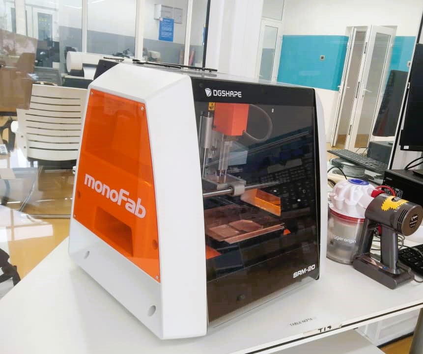
In this week we characterized the specification of the PCB (Printed Circuit Board)Production process and learned how to mill our board using Milling Machine. To mill the board we used SRM 20 and mods as a software to convert PNG to RML file as the SRM 20 reads only RML file. To run SRM 20 we used VPanel.
Assignments
Group assignment: - characterize the design rules for your in-house PCB production process - extra credit: send a PCB out to a board house Individual assignment: - make and test the development board that you designed to interact and communicate with an embedded microcontroller - extra credit: make it with another process
Link to the group assignment is here
PCB Fabrication
I will use the same board that I designed in Electronics design week. I want to control the LED light using a Push button.
Components I used
- MCU ATTiny1614
- Resistors (3 nos of 499 ohm)
- Capacitor
- LED (2nos.)
- Push button
- 3 pin header connector for UPDI
- 6 pin header connector for FTDI
Materials I used
- Single sided PCB board
- Double sided tape
- End mills 1/64 and 1/32”
- Scraper
- Vacuum cleaner
- Brush
- Soldering iron
- Soldering lead and flux
- Solder iron stand and PCB holder
- Tweezer
Mods.
MOD is a software developed by MIT for easier use of different machines like Roland vinyl cutter, SRM milling machine, 3D printers. In our lab we use Mods only for PCB milling.
Some of the navigation keys:
- Open the Mods
- Press left mouse button to drag.
- Scroll button for zoom in and out.
- Right click for getting the new option menu.
Using mods
-
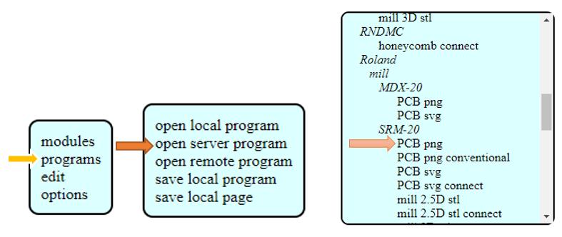
Click on program >> Open server program
-
Scroll down to find the machine that is going to be used. My file format is PNG so I selected PCB PNG under SRM-20.
-
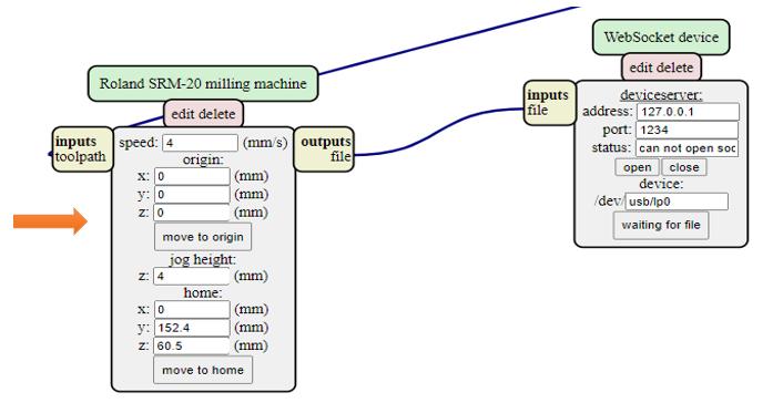
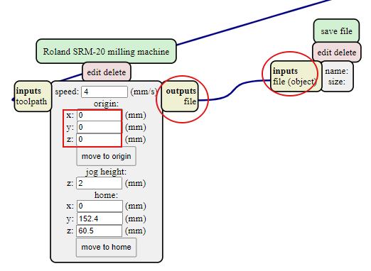
Go to Roland SRM-20 milling machine and set the origin XYZ to zero.
-
Delete the box shown below by clicking on Delete.
-
Right click to get a Save menu to save our RML file. Click to module >> open server module. Scroll down to find save option under file and click on save. It allows to download RML automatically.
-
Connect input and output by clicking on input and then output subsequently.
-
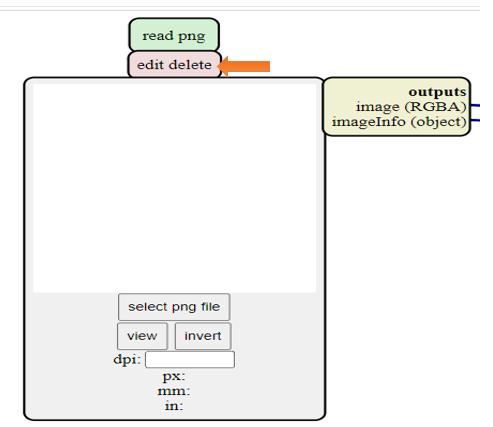
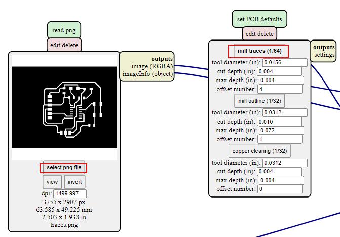
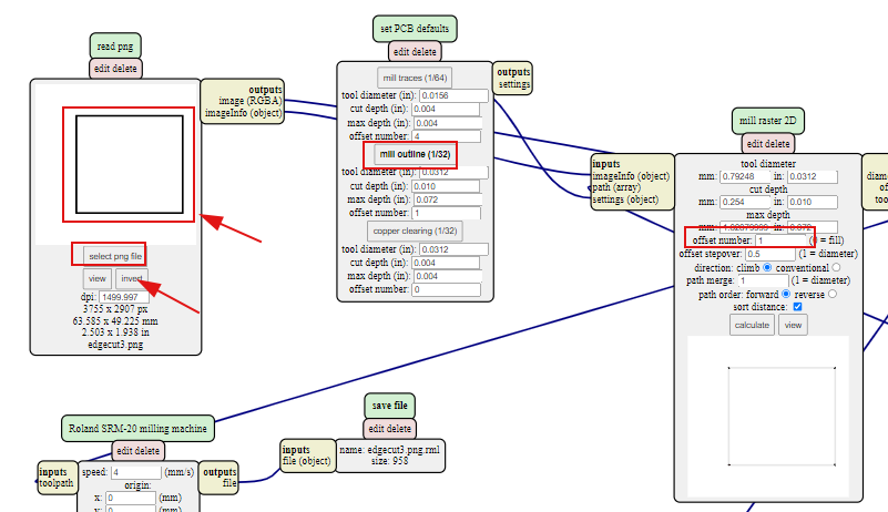
To upload a file click on Select PNG file. Click on invert only for edge cut.
-
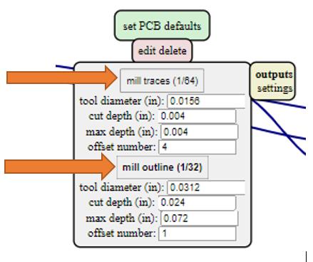
For the traces milling click on Mill Traces and for the outline and drill hole click on Mill outline
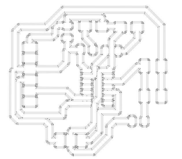
This is the tool path generated for traces with offset number 4.
-
For milling outline/edge cut do invert. The black portion gets milled. This is where we actually gets confused.
Using SRM 20
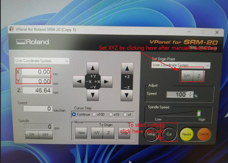
Power ON the machine and open the VPanel. Make sure the lid is closed. Adjust XY position manually to required position and set it to 0.
Change bit as required ( 1/64” for traces cut and 1/32” for drill hole and outline).
To change the bit move the spindle at the high position and tighten slightly.Do not over tighten it because it’s thread is small and it can easily get damaged.
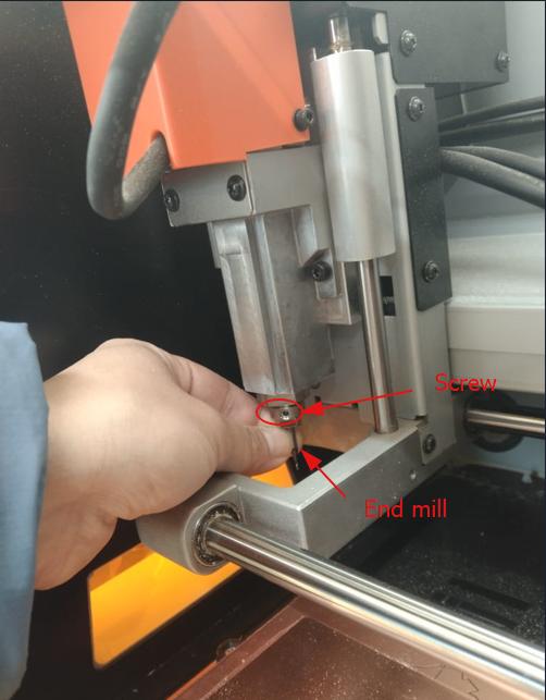
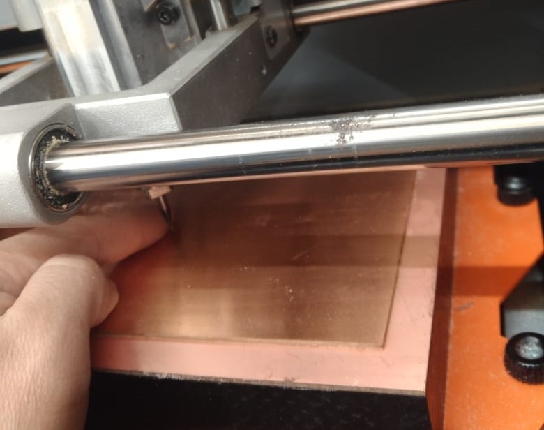
To adjust Z axis to zero move the spindle in the middle of the board and drop the bit lightly on board. Lightly press the board and gently tighten the screw.
Adjust the Z axis and set it to 0 from the VPanel. Do not forget it to rise the Z position up to 1mm to prevent the bit breaking when spindle starts.
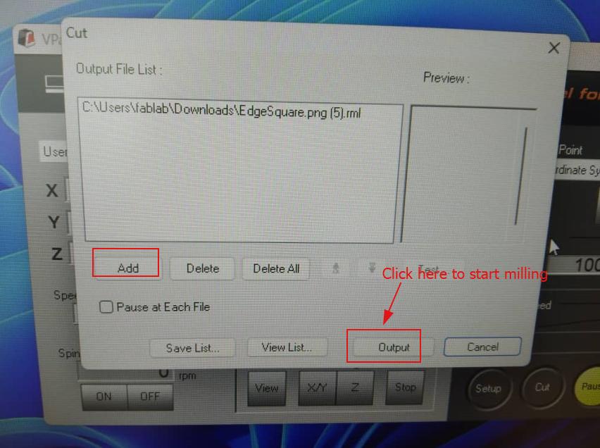
Go to Cut option in the VPanel to choose and upload file. Delete the existing file and add new file and start milling by clicking on OUTPUT.
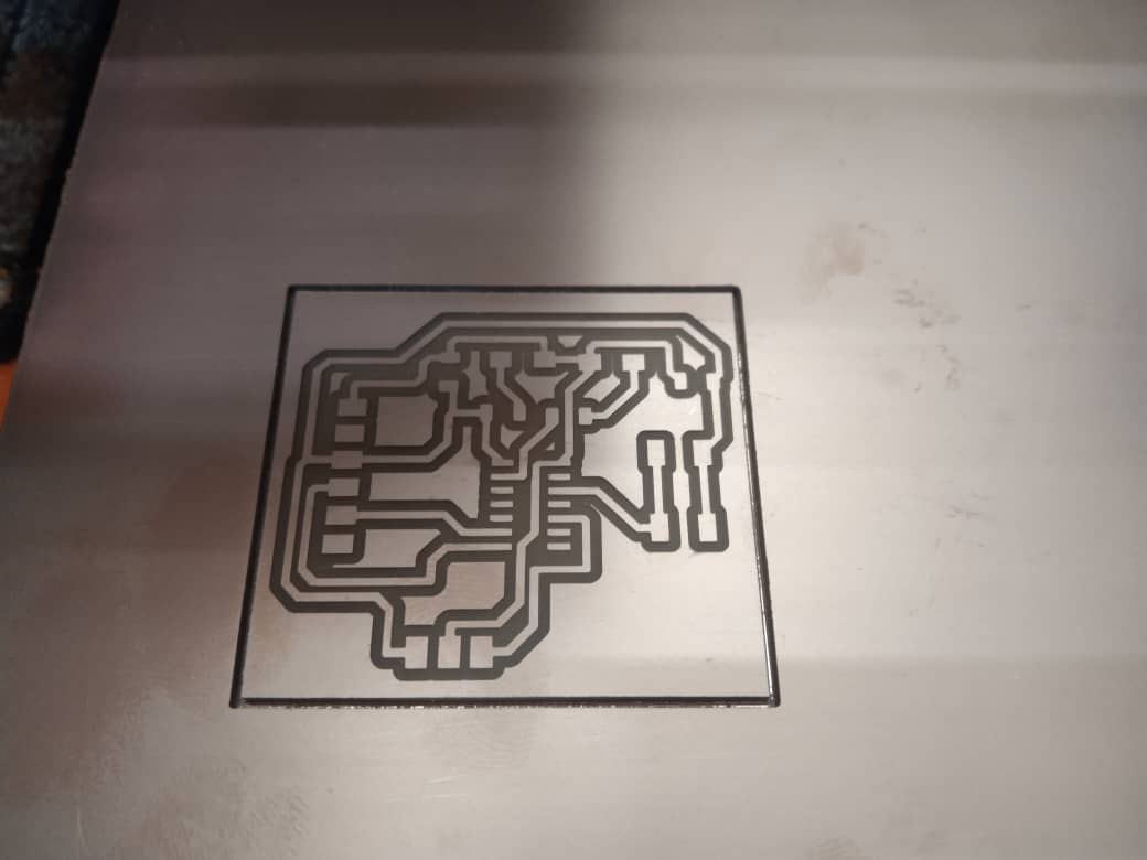
CLean the dust with vacuum cleaner and remove the board carefully with metal scraper.
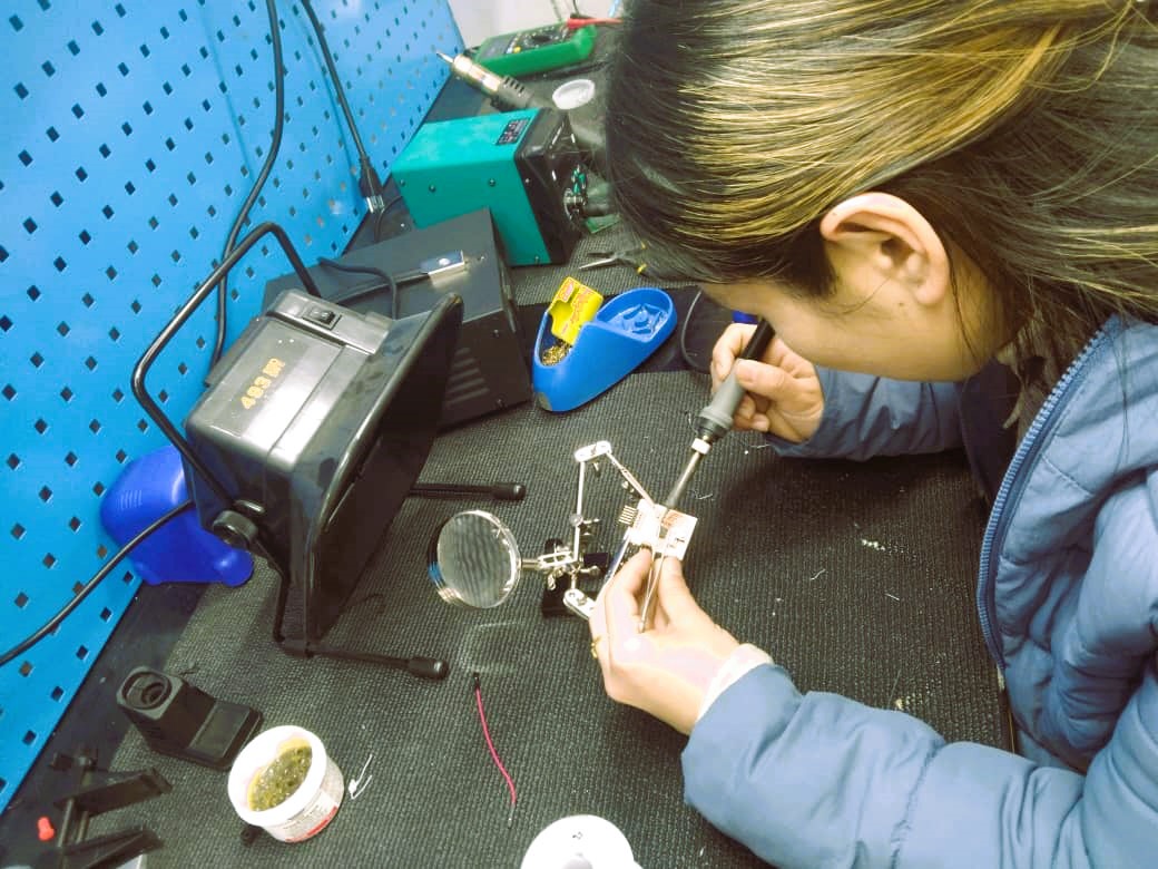
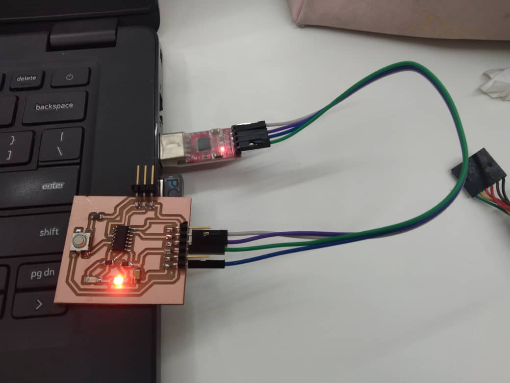
I did stuffing the board with the components. Before doing this I did continuity test using multimeter and I found it working.
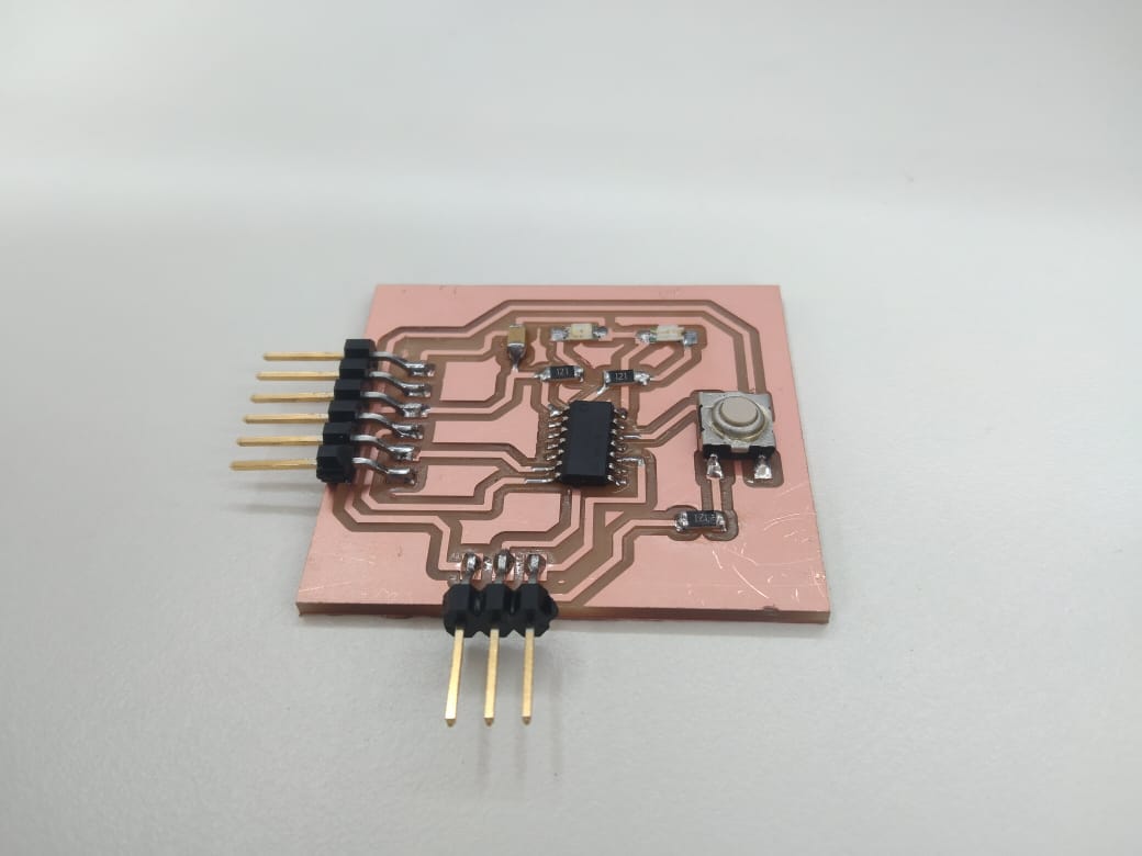
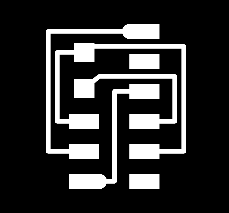
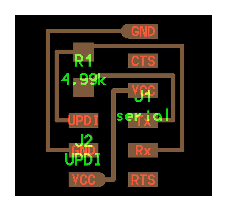
To programme the board I milled the UPDI board and soldered the components. The png files for the UPDI is here >> traces outline board
Programming the board
LED blink test
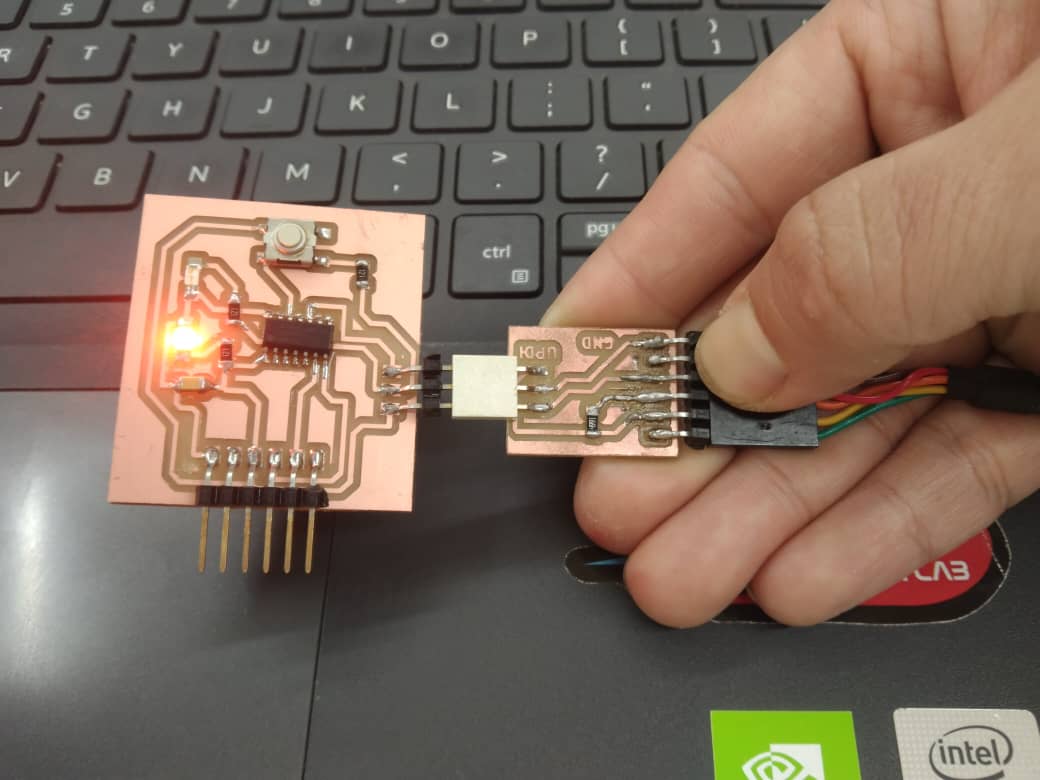
To programme the board I used UPDI connected to my board through 3 pin header.
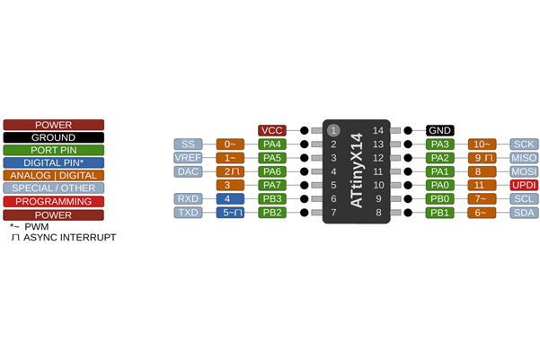
Firstly I did a LED blink test to confirm that my board is working. I usually make mistake in defining pins as I directly look the pin number in schematic or PCB editor and define the pins and board didn’t work. So I referred the pin out diagram shown below under serial communication. My LED pin is on pin number 2–PA4 which is actually pin number 0. I used the code from Arduino IDE example set and I only changed my pin number to 0.
// C++ code

void setup()
{
pinMode(0, OUTPUT);

}

void loop()
{

digitalWrite(0, HIGH);   // turn the LED on (HIGH is the voltage level)
delay(1000);                       // wait for a second
digitalWrite(0, LOW);    // turn the LED off by making the voltage LOW
delay(1000);

}
Push Button
I wanted to control the LED with push button but I made mistakes that I did not give power to button and it didn’t work like I wanted it to be. So I went back to Schematic and given power to button and milled the board again.
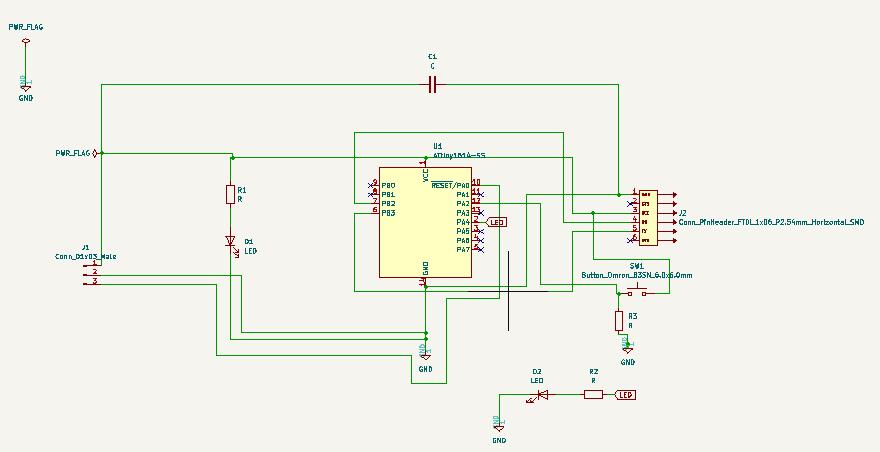
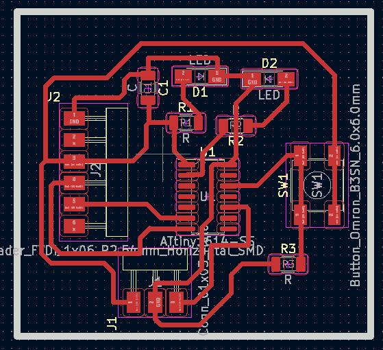
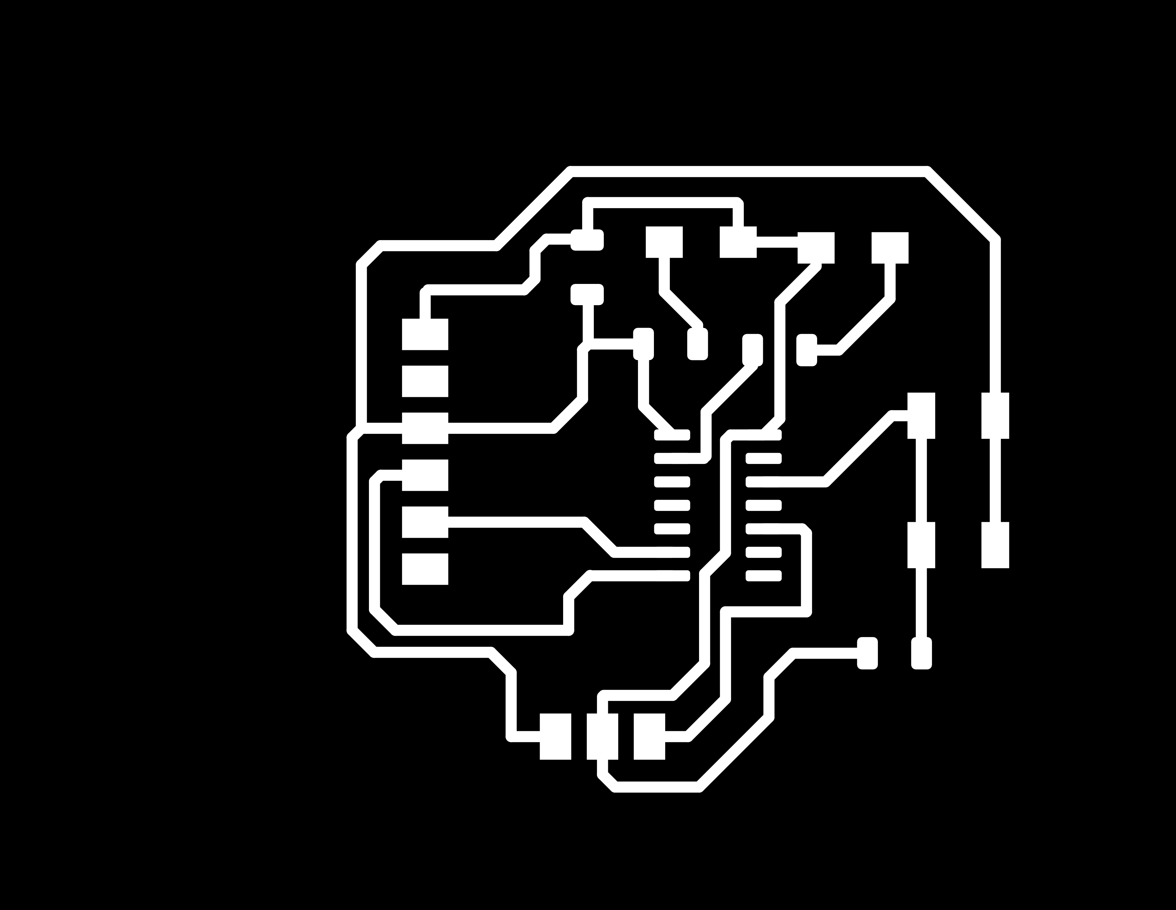
I made a PCB layout as shown below in picture. It is quite challenging for beginners to arrange the component in the PCB editor.
Programming the pushbutton
To programme the push button I used the example code from Arduino IDE and replaced the pin number. I used pin 0 for LED and in 9 for push button. Yes, it worked now.
// C++ code
void setup()
{

   pinMode(0, OUTPUT);  // initialize the LED pin as an output:
   pinMode(9, INPUT);    // initialize the pushbutton pin as an input:
}

    void loop() {

buttonState = digitalRead(9);     // read the state of the pushbutton value:

// if the pushbutton is pressed the buttonState is HIGH:

if (buttonState == HIGH)
{

    digitalWrite(0, HIGH);

}

else {
    // turn LED off:
    digitalWrite(0, LOW);
}
}
Serial communication
To communicate the board through serial monitor I uploaded the code as below using UPDI.
void setup()
{
pinMode(0, OUTPUT);
Serial.begin(57600);
while (!Serial);
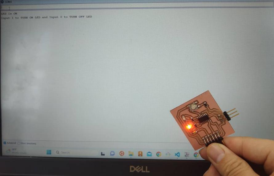
Serial.println("Input 1 to TURN ON LED and Input 0 to TURN OFF LED");
}
void loop() {
if (Serial.available())
{
int state = Serial.parseInt();
if (state == 1)
{
digitalWrite(0, HIGH);
Serial.println("LED is ON");
}
else if (state == 0)
{
digitalWrite(0, LOW);
Serial.println("LED is OFF");
}
}
}
To communicate the board I connected RX of USB TTL(Transistor transistor Logic) to TX of the ATTiny1614 and TX to RX and USB serial connected to FTDI on the board(6 pin header)
Reference for the ATTiny1614 pinout I used this image from this page.
In the serial monitor window the message pup up saying “Input 1 to turn ON LED and input 0 to turn OFF LED”.
Video of serial monitor communication
Electronics basic questions
-
What is circuit?
Ans: It is a complete circular path through which electricity pass through. A Simple circuit consist of power source, conductor and the load. As a general circuit is not passes electricity but also passes data and signal.
-
What are different power source?
Ans: As per Energy Information administration.gov it states five different types of power source as below:
- Hydropower
- Biofuel
- Biomass
- Wind
- Geothermal
- Solar
-
What is load?
Ans: In electronics load refers to the amount of power or current that is drawn from power source by a device and it is typically measured in ohms.
-
What is a conductor?
Ans: Conductor is a material through which the electrical charge passes through. Conductors are typically metals such as steel, brass, aluminum, copper and gold having high density of free electrons. 5. What is the difference between Voltage, Current and Resistance?
Ans:
-
Voltage: It is a measure of the electric potential energy per unit charge in a circuit. It is also called as the electrical potential difference. It is measured in Volts and represented by symbol V.
-
Current: It is the flow of electric charge through a conductor in a circuit. It is measured in terms of Amperes(A) and represented by symbol I.
- Resistance: It is the property of the material which determines how much it opposes the flow of current through it. It is measured in Ohms (Ω)
-
-
What is Ohm’s Law?
Ans: Ohm’s Law states that the current through a conductor between two points is directly proportional to the voltage across the two points. Which states V=IR (R is constant)
-
What does Resistor do?
Ans: Resistor is actually a electronic component which limits the flow of electric current in a circuit. The amount of resistance offered by the resistor is measure in Ohms(Ω). Without the use of resistor in a circuit the components can get damaged due to current overflow.
-
What does Capacitor do?
Ans: It is also a electronic component which stores charges temporarily. The amount of energy the capacitor can stor can be determined by the capacitance and measured in Farad(F) -
What does Diode do?
Ans: Diode allows the electric current to flow only in one direction like a one way valve. It has two terminals Anode and Cathode. When the voltage is applied across the diode the current flows from anode to cathode and if the curren is applied in reverse direction the diode act as an open circuit and blocks the current flow. 10. What does LED mean?
Ans: LED is a electronics device which stands for Light Emitting Diode. It emits light when the electric current passes though it in forward direction.
-
What is a Regulator?
Ans: Regulator is a electronic device which stabilize the output voltage or current of a power supply to a specific level despite variation in input voltage or load current.
-
What is a Bypass Capacitor?
Ans: The bypass capacitor provides a low-impedance path for high-frequency current to bypass a particular component or circuit, such as an integrated circuit or a power supply. It is used in a circuit to reduce noise and voltage ripples in a circuit.
-
What is Current Limiting Resistor for an LED do?
Ans: The current limiting resistor restricts the amount of current that flows through the LED to a safe level and protects the LED from damage. The value of the current limiting resistor depends on the characteristics of the LED and the voltage of the power supply.
-
How are capacitor used as High-pass and Low-pass filters? What does it filter?
Ans: Capacitors are used as passive components in electronic circuits to create high-pass and low-pass filters.
- In a high-pass filter, a capacitor is connected in series with a resistor to allow high-frequency signals to pass through while blocking low-frequency signals.
- In a low-pass filter, a capacitor is connected in parallel with a resistor to allow low-frequency signals to pass through while blocking high-frequency signals. The cutoff frequency of the filter is determined by the values of the resistor and capacitor.
- As a filter is to allow certain frequencies to pass through while attenuating or blocking others and in short it filter out different frequency ranges of a signal.
-
What is VCC?
Ans: In electronic circuits VCC is often used as a reference voltage to indicate the power supply voltage level.
-
What is GND?
Ans: GND stands for Ground and it refers to a common reference point in an electronic circuit that has zero volts potential.
-
What is Common Ground?
Ans: It is a shared reference point which is typically connected to the negative terminal of the power supply or to a conductive surface that is at the same potential as the earth.
-
What is Ground Plane and why is it used?
Ans: A ground plane is a large area of copper on a printed circuit board (PCB). It is used to provide a low-impedance path for electrical current to flow to the ground reference.
My learnings:
Even though all this electronics are new for me Now I understand something. Thanks to Guru Rico for giving us to solve the questions above.
Design file for this week is here