Week 04. Embedded Programming
The main topic that made me excited to join Fab Academy was the Electronics design and programming. But to be honest I do not have any knowledge on electronics and programming. By the end of this week I am happy that I can now do simple codding using Arduino board.
What is program? -It is a series of instructions that makes a micro-controller to perform a particular task. -It contains and various memory addresses on which the instructions work to perform a specific task.
Programming -It is the process of creating a instructions that a computer can understand to perform specific task. It is written in a programming language such as Python, Java script or C++ and are typically called as code.
Assignments
- Group Assignment:
-
compare the performance and development workflows for other architectures.
-
Individual assignment:
- browse through the data sheet for your micro-controller.
- program a micro-controller development board to interact (LED/ Button) (locally) and communicate (remotely).
- Extra credit: use different languages &/or development environments.
Group Assignment is linked here group Assignment
Arduino
It is an open source electronics platform consisting both physical programmable circuit board(Micro-controller)and a software(IDE). We can tell the board to what to do by sending a set of instructions to the micro-controller on the board. If we write a programme to control something and upload it to the micro-controller on the board then the arduino behaves according to the programme. Therefore, Arduino itself is not a micro-controller but a development board.
I found this link a good reference for arduino.
Tinkercad
Before this Fabacademy I use to play with Arduino UNO in tinkercad which is bit easier and convinent for the beginners to learn programming.
- Tinkercad is not only for 3D design but it also provides platform to learn and play with circuit designing and programming which makes learning easier for the begginers providing features like block code and text based code and simulation.
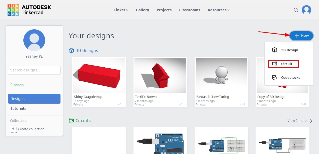
Designing Circuit in Tinkercad - To use tinkercad make sure you have account created. Once you have tinkercad account we can sign in and start working in it. To create a any new design click on +New button as shown below. In Tinkercad we can create electronics circuit and simulate it. For now lets create simple circuit and programme it >> so choose circuit.
- When opening blank page it consist of three main parts.In the right column we can find electronics components which we can drag and drop on work space. We can also search for the components typing its name in the search navigation. The button shown below also shows the short description of the components.
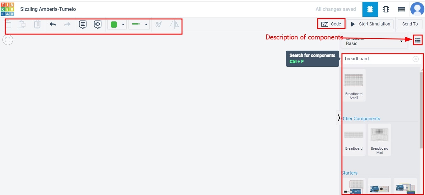
- In order to do programming bring the programable component on the work space. Tinkercad provides block code and text based code.I will bring arduino, bread board, resistor and LED to the work space and connect as below.
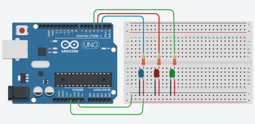
- Now click on Simulation section and you can see the LED blink. To type the code go to the code section.
Code is attached below
// C++ code
//
 void setup()
{
  pinMode(0, OUTPUT);
  pinMode(2, OUTPUT);
  pinMode(3, OUTPUT);
  pinMode(4, OUTPUT);
}

void loop()
{
  digitalWrite(0, HIGH);

  digitalWrite(2, HIGH);
  delay(1000); // Wait for 1000 millisecond(s)
  digitalWrite(3, HIGH);
  delay(1000); // Wait for 1000 millisecond(s)
  digitalWrite(4, HIGH);
  delay(1000); // Wait for 1000 millisecond(s)
  digitalWrite(4, LOW);
  delay(1000); // Wait for 1000 millisecond(s)
  digitalWrite(3, LOW);
  delay(1000); // Wait for 1000 millisecond(s)
  digitalWrite(2, LOW);
  delay(1000); // Wait for 1000 millisecond(s)

  digitalWrite(2, HIGH);
  delay(1000); // Wait for 1000 millisecond(s)
  digitalWrite(0, HIGH);
  delay(1000); // Wait for 1000 millisecond(s)
  digitalWrite(0, HIGH);

  digitalWrite(0, HIGH);

  digitalWrite(2, HIGH);
  delay(1000); // Wait for 1000 millisecond(s)
  digitalWrite(0, HIGH);
  delay(1000); // Wait for 1000 millisecond(s)
  digitalWrite(0, HIGH);
}
To begin with hands on learning on programming I collected a Arduino Uno R3 and ESP 32. Comparing this two I found out both works almost similar. However, ESP 32 looks more convineient if we are using module like bluetooth, wifi and other module because we do not have to give a separate module.
To programme the board we need to install Arduino IDE software. To install the Arduino IDE go to IDE download
Setting up Arduino IDE
IDE is a software that contains all the essential tools to develop, compile, link, and debug your code. As I already used IDE it is already downloaded and installed. However, I need to download the ESP32 boards where as MegaTINYcore and ATTINNYcore are already installed.
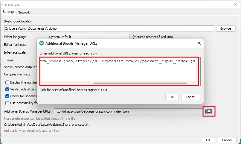
- Firstly go to File >> Preferences >>
- Paste the URL in the box in Additional Board Manager URL. Separate the two URL using comma.
-
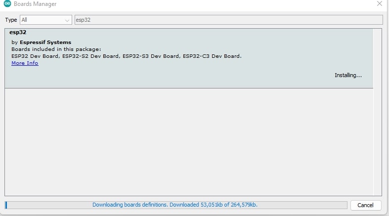
I downloaded the libraries for ESP32 and the link for the ESP is here ESP32
-
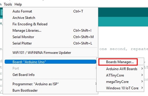
Go tot tool >> Board Manager >> Search by typing the name ans click on Install. Libraries will be installed.
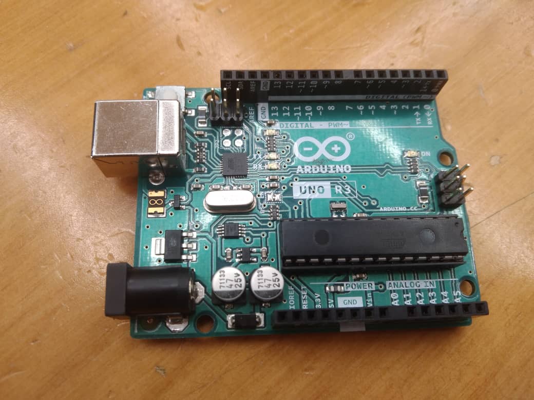
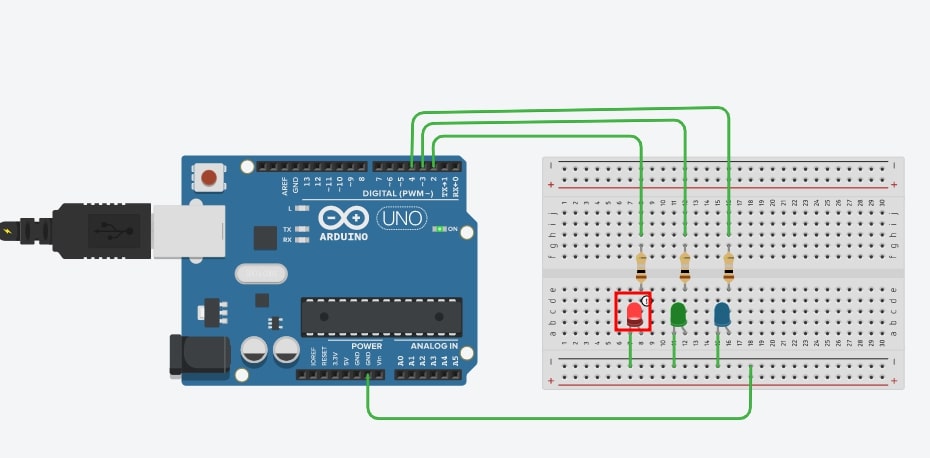
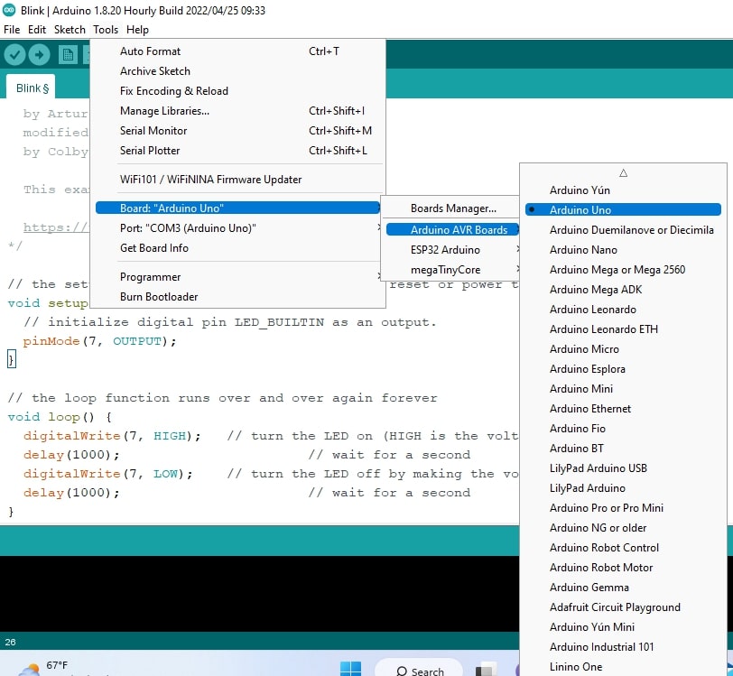
- I already have Arduino Uno with me so I want to convert the circuit I have made in tinkercad into the actual board. I connected the components same as the connecion I made in Tinkercad. To programme I have to select the board as Arduino Uno.
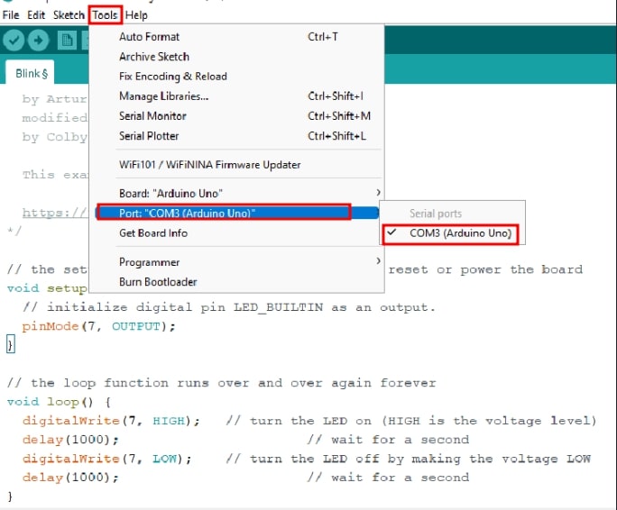
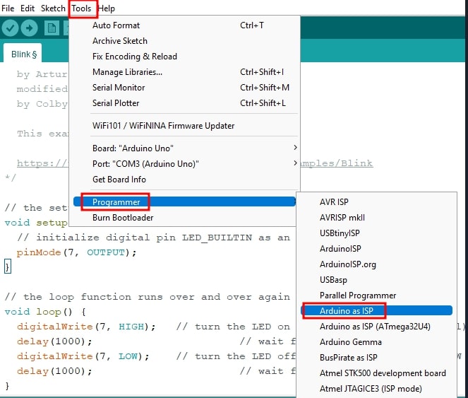
- I selected the port through which the Arduino is connected through USB and selected the programmer to Arduino as ISP.
- Then I copied the text code from Tinkercad and pasted in IDE and did varification and then uploaded. The circuit worked correctly as shown below in video.
Individual Assignment
I was given the Arduino UNO R3 and learned how to used it but I need to know its detail features therefore I want to browse datasheet of Arduino UNO R3 and its micro controller ATMega328P.
-
Arduino UNO R3 is a small programmable microcontroller board where we can build up electronics projects.
-
It is equipped with amin processor ATMega328P running up to 20MHz and ATMega 16U2 Processor. It has 14 digital has 14 digital input and output pins, 6 analog input pins, USB connection, a power jack, and a ICSP header for programming the microcontroller.
-
The minimum voltage we can give from VIN is 6Volts and maximum voltage is 20Volts and maximum voltage from USB IS 5.5Volts.Here is the to refer the data sheet I referred data sheet
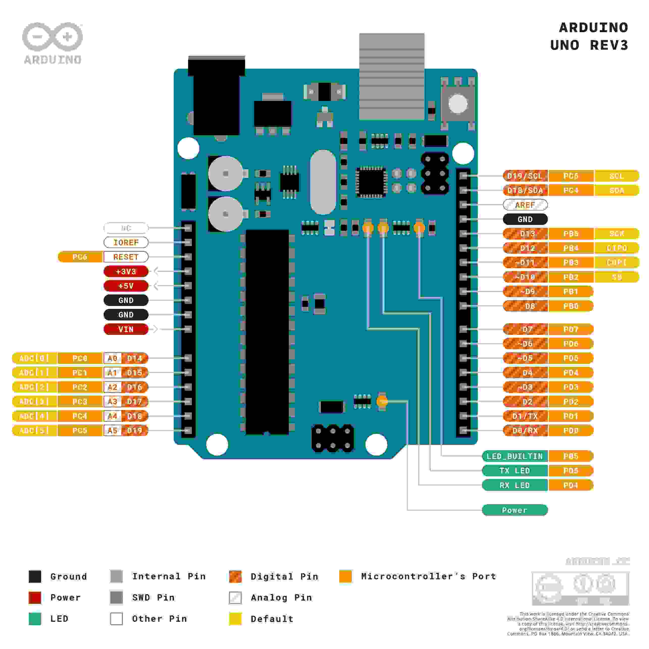
- Image source Pin out
ATMega328P
-
The ATMega328P is a 8-bit microcontroller with 32KB of flash memory for storing the code.
-
It has 2KB of SRAM (a type of random access memory that retains data bits in its memory as long as power is being supplied)for data storage.
-
1KB of EEPROM(Does not lose its data when power supply is cut off and can be erased and reprogrammed) for non-volatile storage.
-
It runs at 16 MHz(Million Hertz:speed at which data moves within and between components).
-
Link to the data sheet I referred ATMega328P
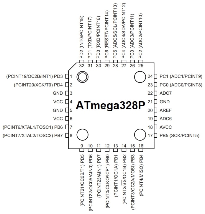
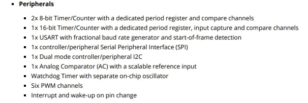
- Some of the important peripheral features are: