Week 14. Networking and Communications
Assignment
Individual assignment:
- design, build, and connect wired or wireless node(s) with network or bus addresses
Group assignment:
- send a message between two projects
Notes
This week was something different where I got stuck and I referred the tutorials and also took some notes from chatgpt. I referred this tutorial:
Digital data transmission
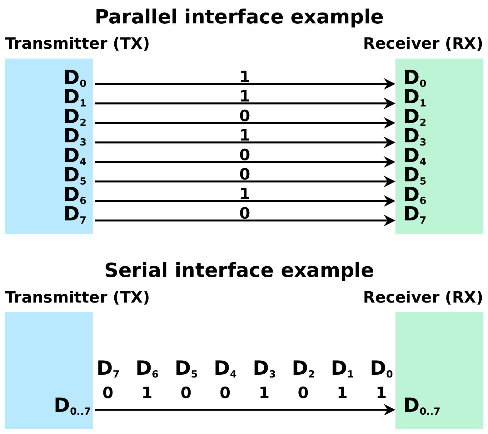
Parallel transmission
- To send 8 bit data it requires 8 lines and data is sent at once.
Serial transmission
-
8 bits of data is sent one after another through single communication line/wire. Types of various Serial communication protocols are such as RS-232, RS-485, UART, SPI, and I2C
Group Assignment
We are divided into girls and boys group whereby we are supposed to work with wired communication.
For the group assignment I referred this link for code .
I took Arduino Mega and Arduino UNO and connected as below. I used PIN 8 and 9 as RX and TX. I connected Pin 8 of arduino Mega to Pin 9 Pin of Arduino Uno and pin 9 of mega to Pin 8 of UNO. Connected 5V TO 5V and GND to GND. I selected the port and board and then I uploaded the programme.
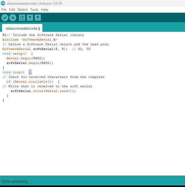
Master code:
    // Include the Software Serial library
    #include <SoftwareSerial.h>
    // Define a Software Serial object and the used pins
    SoftwareSerial softSerial(8, 9);  // RX, TX
    void setup()  {
      Serial.begin(9600);
      softSerial.begin(9600);
    }
    void loop()  {
    // Check for received characters from the computer
      if (Serial.available())  {
    // Write what is received to the soft serial
        softSerial.write(Serial.read());
      }
    }
Slave code:
// Include the Software Serial library
#include <SoftwareSerial.h>
// Define a Software Serial object and the used pins
SoftwareSerial softSerial(8, 9);
// LED Pin
int LED = 13;
void setup()  {
softSerial.begin(9600);
pinMode(LED, OUTPUT);
}
void loop()  {
// Check if there is anything in the soft Serial Buffer
  if (softSerial.available())  {
// Read one value from the soft serial buffer and store it in the variable com
    int com = softSerial.read();
// Act according to the value received
    if (com == 'x')  {
// Stop the LED
      digitalWrite(LED, LOW);
    }
    else if (com == 'a')  {
// Start the LED
    digitalWrite(LED, HIGH);
    }
  }
}
Uploaded the slave code

But it didn’t work this was because I need to connect both arduino through USB. When we type letter “a” LED is ON and when “x” LED is OFF.
Link to the group assignment is here
Individual Assignment
As individual assignment I will use the I2C communication protocol. I want my RTC module to communicate with my final project board as I am using RTC module to keep track of time.
I2C communication protocol:
I referred this tutorial to check the IP address and borrow the code too. To know more on bus address I found this tutorial explained in detail.
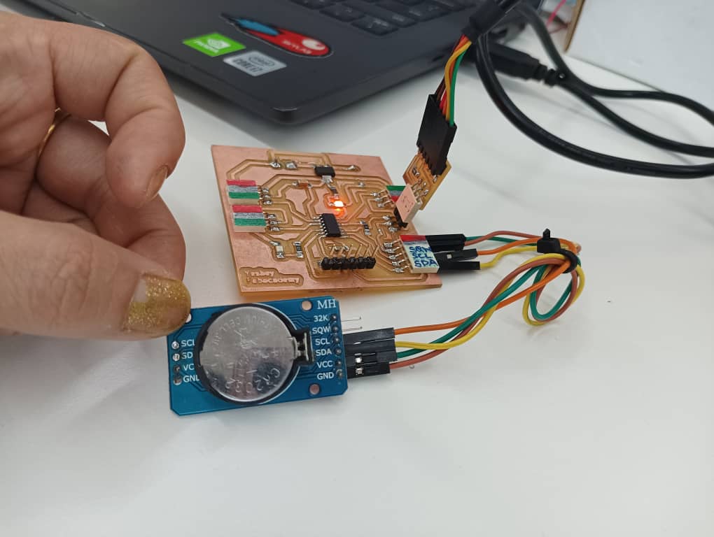
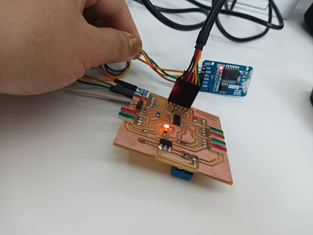
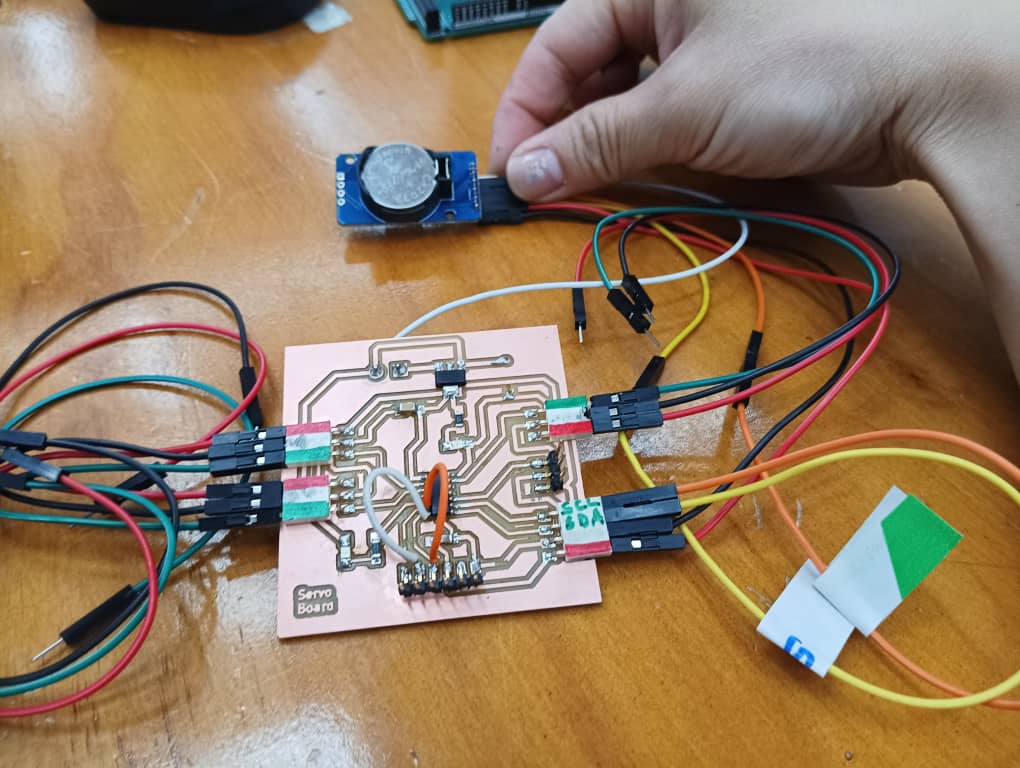
I connected the RTC module to my board (SCL->>SCL, SDA->>SDA, VCC and GND). I uploaded the sketch below to my board ATTiny 1614.
#include <Wire.h>

void setup()
{
  Wire.begin();

  Serial.begin(9600);
}

void loop()
{
  int error;
  int address;
  int devices = 0;

  Serial.println("Devices found:");

  for (address = 1; address < 127; address++ )
  {
    Wire.beginTransmission(address);
    error = Wire.endTransmission();

    if (error == 0)
    {
      Serial.print("0x");
      if (address < 16)
        Serial.print("0");
      Serial.println(address, HEX);
      devices++;
    }

    else if (error == 4)
    {
      Serial.print("Unknown error at address 0x");
      if (address < 16)
        Serial.print("0");
      Serial.println(address, HEX);
    }
  }

  if (devices == 0)
    Serial.println("No I2C devices found");

  delay(5000);
}
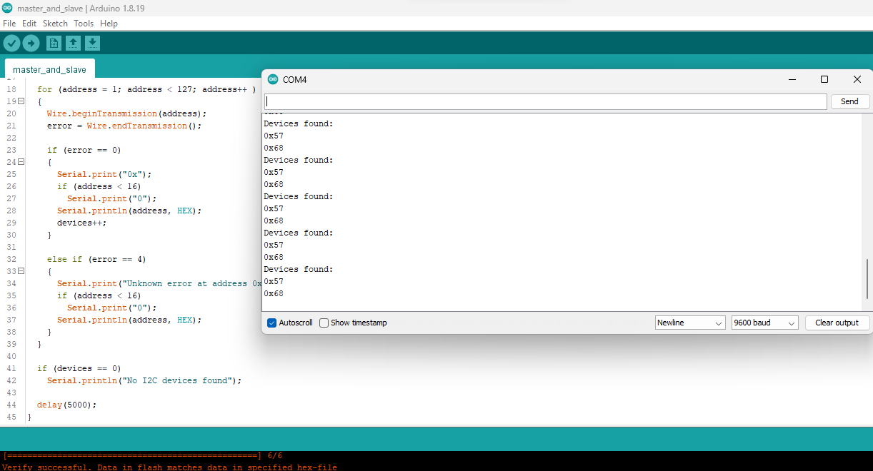
I connected the board through FTDI to see serial monitor.
It shows two addresses(0x68, 0x57) this is because the module has a simple I2C interface that takes up two addresses. The DS3231S RTC chip’s fixed I2C address is 0x68, and the EEPROM’s default I2C address is 0x57 (though the address range is 0x50 to 0x57) according to this link
I connected RTC module on my board and I made a condition statement that the LED should blink when the my board gets feedback from the RTC module when achieving the given statement.
I connected the RTC on my board as below, connected the SDA, SCL and SQW pins of RTC to the SDA,SCL and SQW pins on MCU respectively.
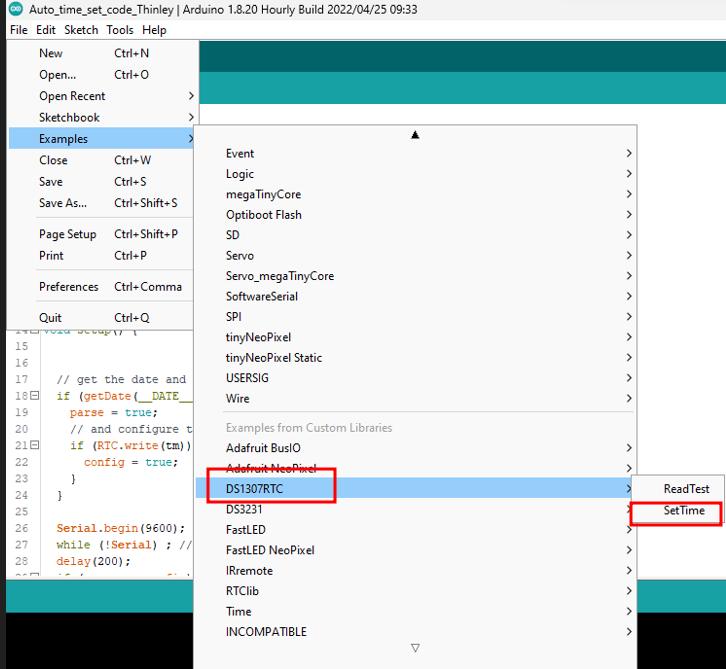
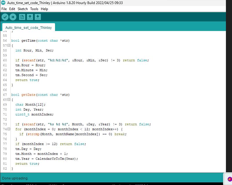
For the code I used the time set example code from library to set the time and uploaded on my board.
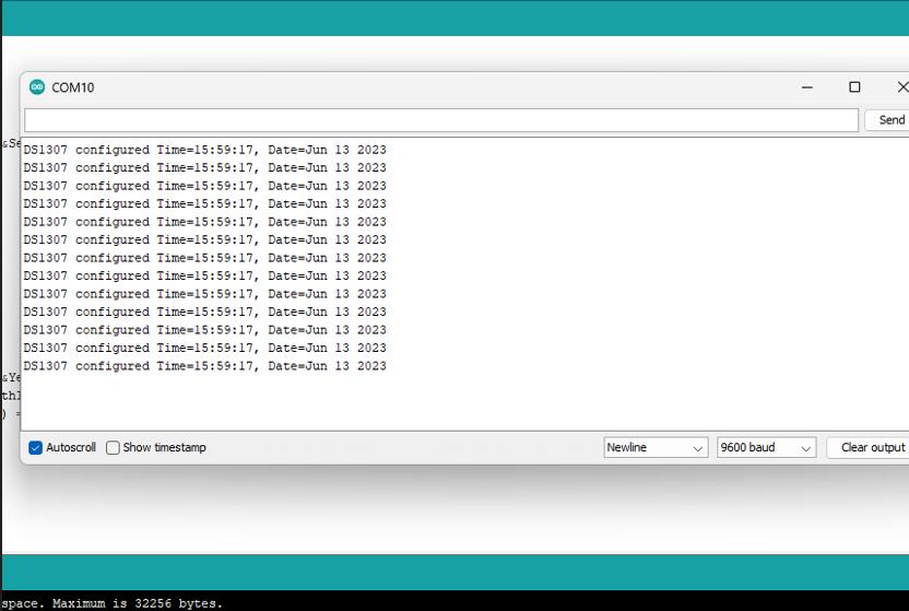
To check whether the time is set or not I did serial monitor. My RTC time got set successfully as shown below.
Communication with my board
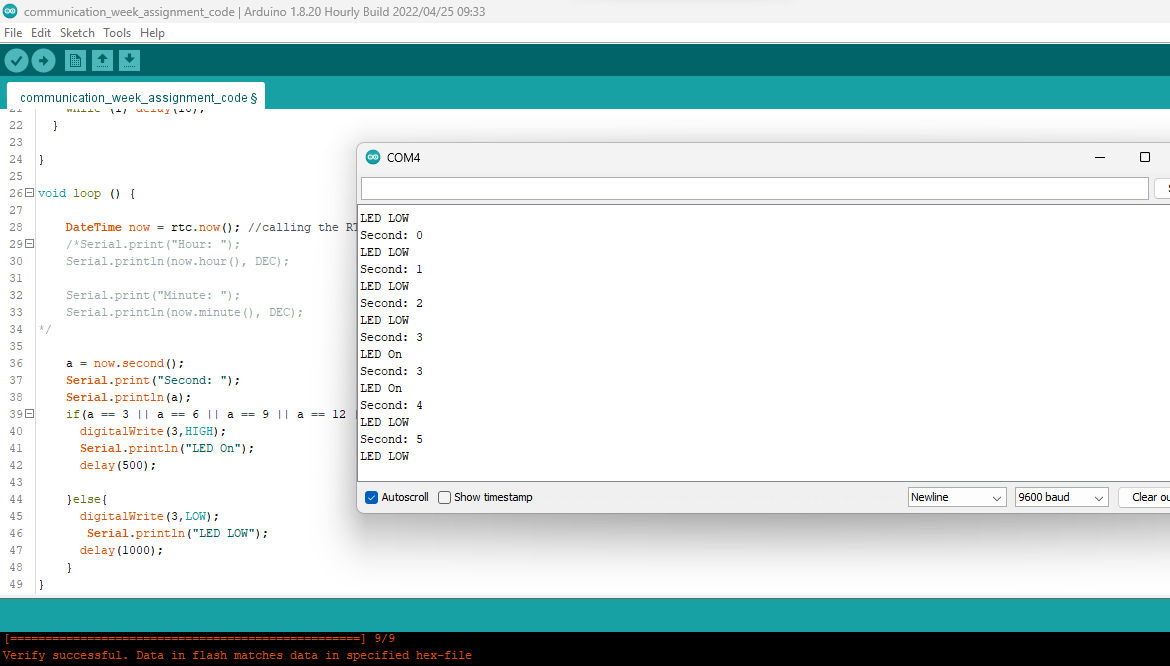
I made a condition based statement to blink the LED after every 3 second in which RTC module will keep record of time and give feedback to MCU making LED blink. I made to print in serial monitor as LED ON and LED lOW.
Selected the board.
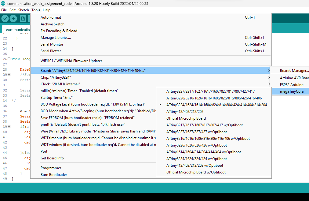
Select the chip.
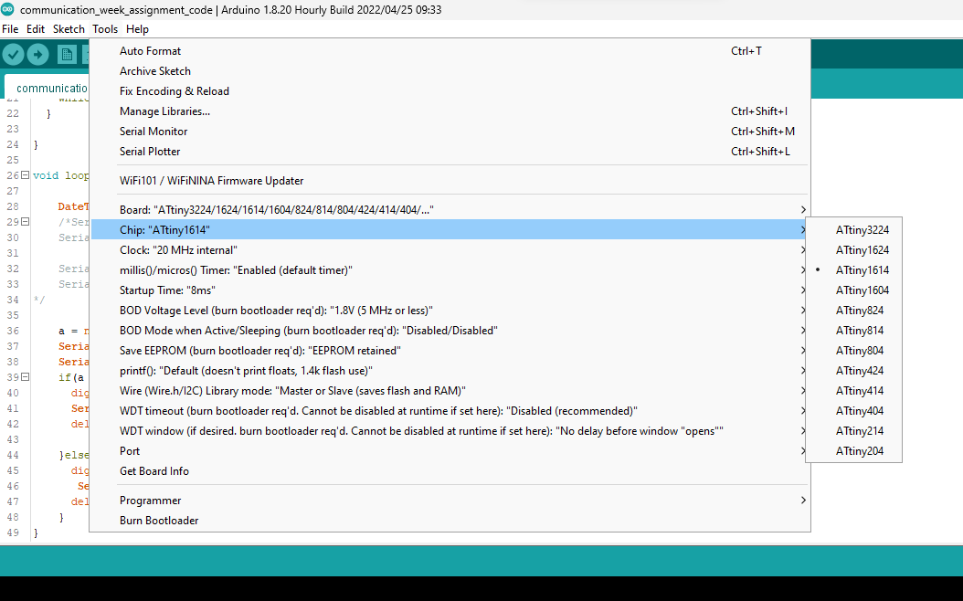
Select the port and upload the code.
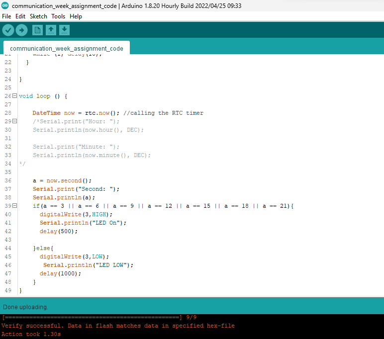
I uploaded the code below.
// Date and time functions using a DS3231 RTC connected via I2C and Wire lib
#include "RTClib.h"

RTC_DS3231 rtc; // initilizating the RTC_DS3231 object

char daysOfTheWeek[7][12] = {"Sunday", "Monday", "Tuesday", "Wednesday", "Thursday", "Friday", "Saturday"};

int a = 0;

void setup () {

  pinMode(3, OUTPUT);

  Serial.begin(9600); // defining the baud rate

  if (! rtc.begin()) {
    Serial.println("Couldn't find RTC");
    Serial.flush();
    while (1) delay(10);
  }

}

void loop () {

  DateTime now = rtc.now(); //calling the RTC timer
  /*Serial.print("Hour: ");
    Serial.println(now.hour(), DEC);

    Serial.print("Minute: ");
    Serial.println(now.minute(), DEC);
  */

  a = now.second();
  Serial.print("Second: ");
  Serial.println(a);
  if (a == 3 || a == 6 || a == 9 || a == 12 || a == 15 || a == 18 || a == 21) {
    digitalWrite(3, HIGH);
    Serial.println("LED On");
    delay(500);

  } else {
    digitalWrite(3, LOW);
    Serial.println("LED LOW");
    delay(1000);
  }
}
I checked in serial monitor to see whether it is working or not and it works.
Zipped code file is attached here