Week 12. Input devices
In this week I learnt about different types input devices and its function. Our Guru Rico did a live demo virtually on how the capacitive sensor works.
Assignment of the week
-
Individual assignment:
- measure something: add a sensor to a microcontroller board that you have designed and read it
-
Group assignment:
-
probe an input device’s analog levels and digital signals
Group assignment
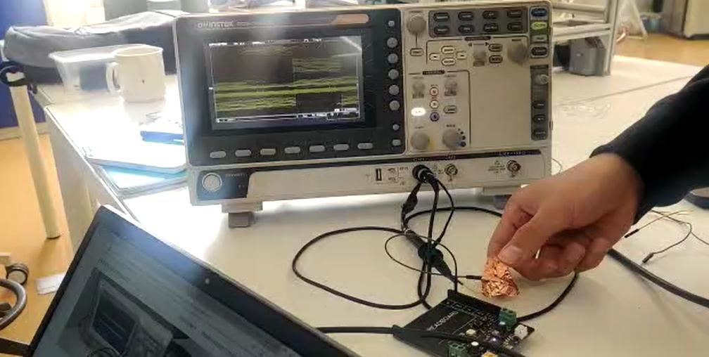
In group we did practical test of digital and analog output using function generator GWINSTEK. We tested the signal for the capacitive test by connecting the soldered copper sheet to the arduino digital pin and connected it to the function generator using prob. When we approach and press the copper sheet the signal gets disturbed.
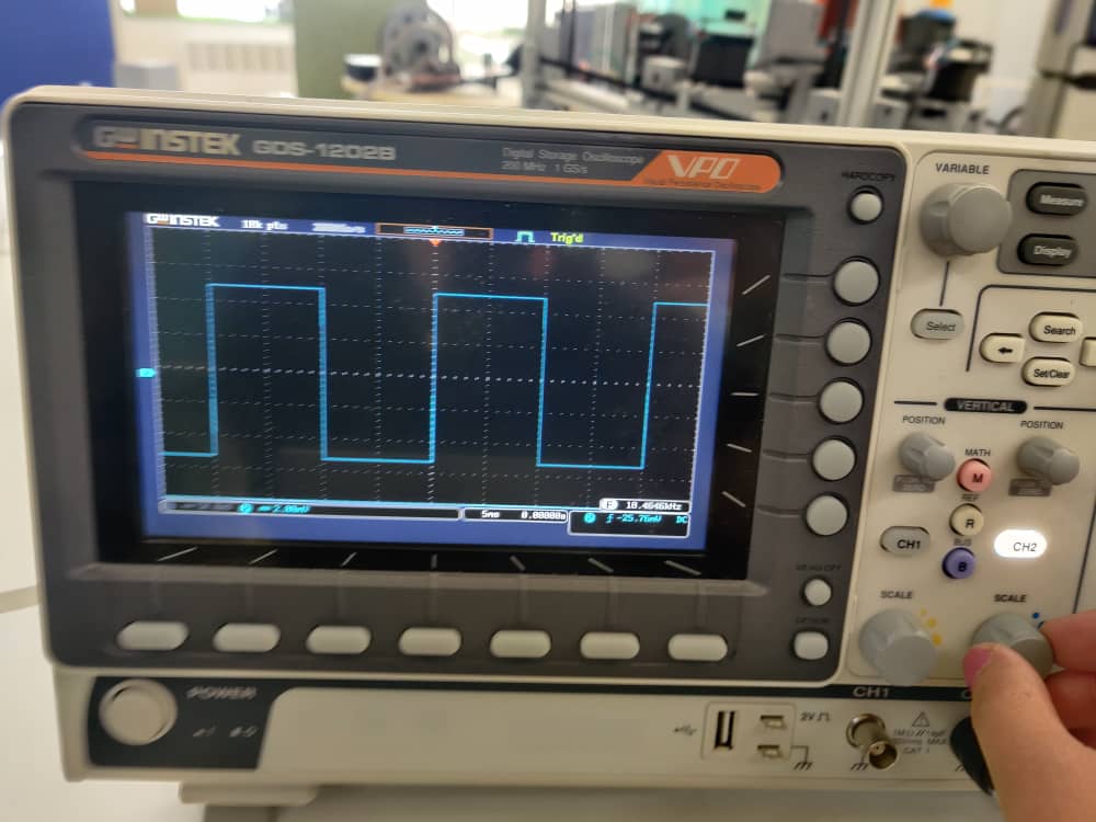
More on group assignment is linked here.
Individual Assignment
This week assignment was to test the any input devices such as sensors or push button(not recommended) Our Guru Rico and local Instructor Zina asked us to test the input device related to our project. So, so wanted test PIR sensor and LDR sensor.
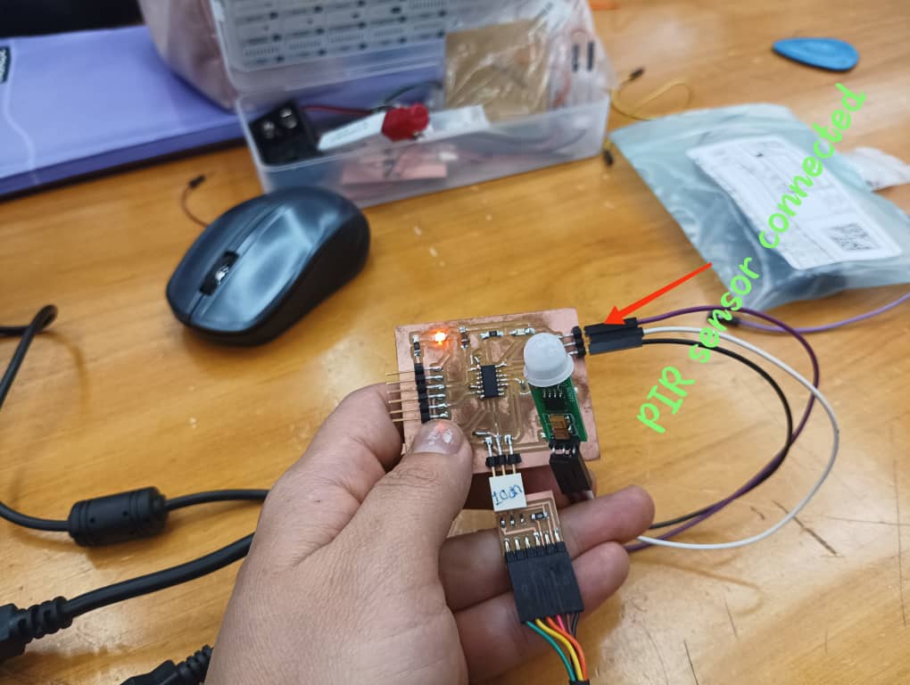
I used the same board I used in output device week but I add one LED for output as shown below. I milled the board and soldered the board.
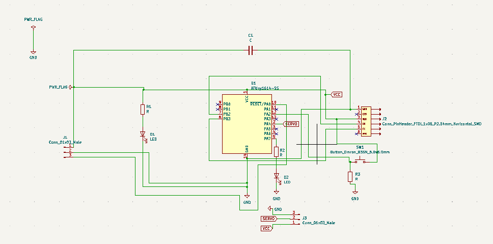
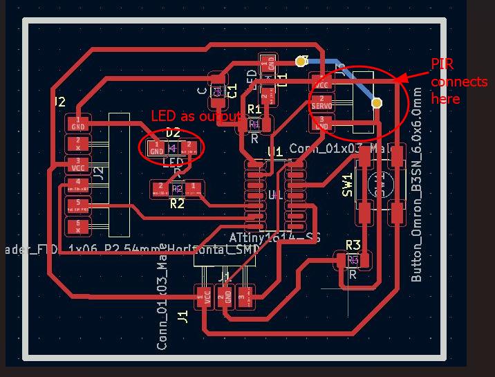
I connected PIR sensor to the 3pin header where there was the servo motor as an output device initially.
I connected the VCC to VCC and GND to GND pin, signal pin to the Attiny1614 pin out number 0.
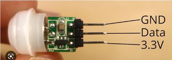
When connecting the sensor I burnt the PIR sensor as the pin I referred was for different PIR sensor. So I kept on finding the exact pinout for AM 312 PIR sensor.
Pinout for PIR sensor
I referred this link for the code.
In my board I have LED on pin number 3 which is output and it turn ON when PIR sensor sense the motion. I connected the PIR sensor to servo pin which is pin number 0 and it is an input.
Code is here
int led = 3;                // the pin that the LED is attached to
int sensor = 0;              // the pin that the sensor is atteched to
int state = LOW;             // by default, no motion detected
int val = 0;                 // variable to store the sensor status (value)

void setup() {
pinMode(led, OUTPUT);      // initalize LED as an output
pinMode(sensor, INPUT);    // initialize sensor as an input
Serial.begin(9600);        // initialize serial
}

void loop(){
val = digitalRead(sensor);   // read sensor value
if (val == HIGH) {           // check if the sensor is HIGH
    digitalWrite(led, HIGH);   // turn LED ON
    delay(100);                // delay 100 milliseconds

    if (state == LOW) {
    Serial.println("Motion detected!");
    state = HIGH;       // update variable state to HIGH
    }
}
else {
    digitalWrite(led, LOW); // turn LED OFF
    delay(200);             // delay 200 milliseconds

    if (state == HIGH){
        Serial.println("Motion stopped!");
        state = LOW;       // update variable state to LOW
    }
}
}
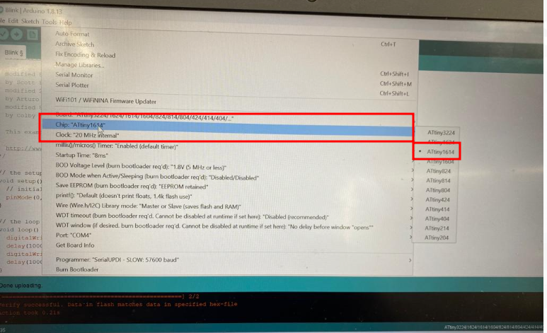
Uploading the code
-
Selected the board.
-
Selected the programmer.
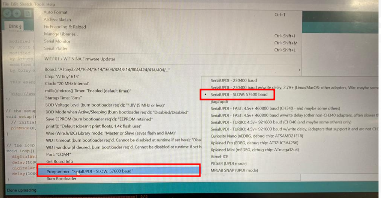
- Selected the port.
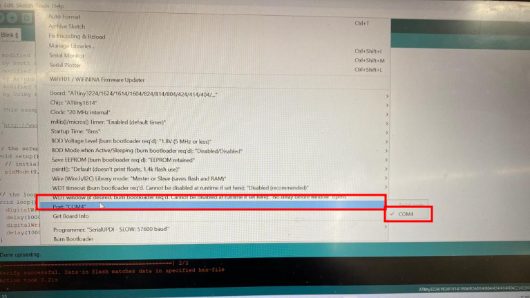
- I compiled the programme and uploaded the programme.
Unfortunately my board wasn’t responding and saying UPDI initializaiton failed when uploading program. When checking I found the solder went out. I replaced UPDI and resoldered some of the traces.
Here is the video of working and I noticed that the PIR sensor is sensitive that it detects the little motion nearby.
Design file for this week is here