Week 10 & 11. Mechanical design, Machine Design
In this week we were supposed to make a machine and we divided into two groups namely boys and girls group. This week was challenging and interesting as well.
Group assignment
- design a machine that includes mechanism+actuation+automation+application
- build the mechanical parts and operate it manually
- document the group project and your individual contribution
Group Assignment
Link to the group assignment is here.
Firstly, we discussed about what machine we are going to make. Out of many options we got inspired to something cute but useful so we decided to make cute vacuum cleaner.
Why tinny vacuum cleaner?
Since the requirement for this week’s assignment was to design a machine that includes mechanism, actuation, automation and application so this little vacuum cleaner was a perfect project and it is simple to make with few components and every household can have a this little cleaner at cheaper rate because components we are using are not much expensive.
Work distribution
Karma Lhaki
- Team Lead
- Leaser and vinyl cutting
- Programming
- Assembling components
Ugyen Lhamo
- Video and photography
- Assembling components
- Programming
- Documentation
Yeshey Wangmo
- 3D and 2D design
- 3D printing and laser cutting’
- Assembling the components
- Programming
Materials used:
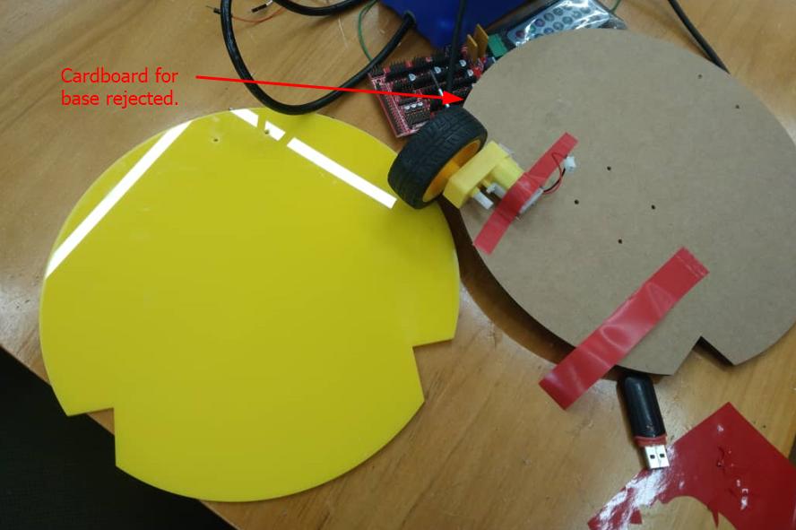
- Acrylic at the base to hold on the components.
- Cardboard for the body to cover the components inside.
- breadboard, Arduino Nano, Jumper wires.
- DC motor and gears
- Ultrasonic sensor to detect the obstacles,
- 12V battery:We used 5v for arduino and motors and 12V for the fan.
- Stepper Motor driver to convert the low current signal.
- Jumper wires for connection.
- Keyes SR1y Relay Module is used to control the flow of electricity.
- IR receiver with remotes for on and off instead of switch button.
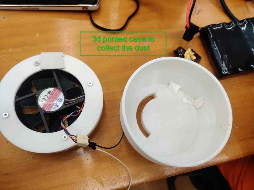
- Fan with 12V for suction.
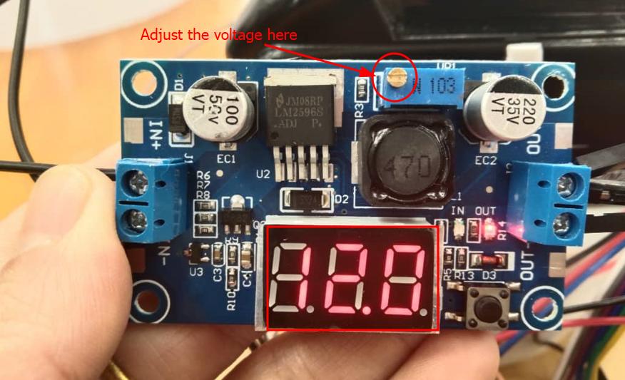
- buck converter to step down voltage of the given input in order to achieve required output. We tried arranging 12V battery but we couldn’t find it and it is interesting that we took out the battery from hand drilling machine and used buck converter to step down it’s voltage to 12V(Actual vontage was 18V).
Workflow
We used fusion 360 to design the cover of the machine and the dust collector and did 3D print the dust collector and laser cut the exterior casing.
For thr base firstly we made with the cardboard but it is getting bend due to weight of the battery so we switch over in using acrylic.
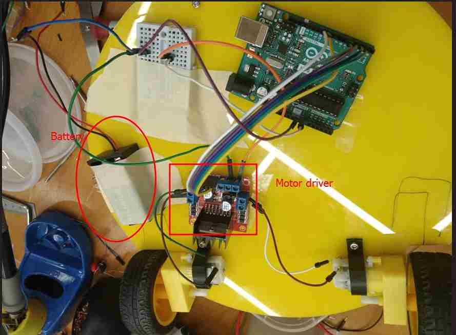
Then we attached the wheels and the motors to the base and attached the caster wheel on the front to make it stable. We worked on circuit connection. Initially we used 9V duracell battery to run the motor but we couldn’t taste fan and the motor at once as we didn’t had 12V battery in the lab.
Connection of pins
  Arduino uno R3    Motor driver
  Pin 2         →     In 1
  Pin 3          →     In 2
  Pin  4         →     In 3
  Pin 5          →     In 4
  Pin 9          →     ENA
  Pin 10         →     ENB
  GND            →     Breadboard any pin
  VIN            →     Breadboard any pin


  Motor Drivers
  Gnd(Middle one ) →  Breadboard GND
  12V (First one ) →    Breadboard VCC

  Motor Drivers

  OUT 1  & OUT 2  →  1st motor with wheel
  OUT 3  & OUT 4  →   2nd motor with wheel.

  9V battery
  +Ve  →   V of breadboard
  -Ve  →   GND of the breadboard

  Remote controlling with the fan
  Arduino uno       IR Receiver
  +Ve  →    Red cable
  GND  →  Black cable
  Pin 9  →   Output

  Relay
  +Ve 5v in arduino
  -Ve GND if arduino
  S  →   pin 7 arduino
Code for initial run test (Referred this code)
  int motor1pin1 = 2;
  int motor1pin2 = 3;

  int motor2pin1 = 4;
  int motor2pin2 = 5;

  void setup() {

  pinMode(motor1pin1, OUTPUT);
  pinMode(motor1pin2, OUTPUT);
  pinMode(motor2pin1, OUTPUT);
  pinMode(motor2pin2, OUTPUT);
  }

  void loop() {

  digitalWrite(motor1pin1, HIGH);
  digitalWrite(motor1pin2, LOW);

  digitalWrite(motor2pin1, HIGH);
  digitalWrite(motor2pin2, LOW);
  delay(1000);

  digitalWrite(motor1pin1, LOW);
  digitalWrite(motor1pin2, HIGH);

  digitalWrite(motor2pin1, LOW);
  digitalWrite(motor2pin2, HIGH);
  delay(1000);
  }
Testing the speed of the motor
The battery is getting drained so fast on trial test only for the wheels. We spend around 2 days on searching battery in market unfortunately we didn’t get one. Lastly we decided to take out the battery from Matika hand drilling machine which is actually 18V and we used buck converter to step down the volTage to 12V.
YES!! Finally we could make our little cleaner run on the floor and we could comfortable do sensor test without draining the battery much.
Trial test 2.
We did a IR receiver test for ON ad OFF using the remote and we used this code below.
  #include <IRremote.h>
  int RECV_PIN = 9;

  int relay = 8;

  void setup() {
  Serial.begin(9600);
  pinMode(relay, OUTPUT);
  IrReceiver.begin(RECV_PIN, ENABLE_LED_FEEDBACK);
  }

  void loop() {

   if (IrReceiver.decode())
  {

  if(IrReceiver.decodedIRData.decodedRawData == 0xF30CFF00) {

  digitalWrite(relay, HIGH); //Serial.println

  (IrReceiver.decodedIRData.decodedRawData, HEX);
  Serial.println("on");
  }

  else if(IrReceiver.decodedIRData.decodedRawData == 0xE916FF00) {

  digitalWrite(relay, LOW);//Serial.println(IrReceiver.decodedIRData.decodedRawData, HEX);
  Serial.println("OFF");
  }

  IrReceiver.resume(); // Receive the next value
  }

  }
Failure It is very important to check the voltage supply distribution. We did not check after connection and we burnt the arduino and sensor. The sensors are getting heated up and this made me wonder. I moved on to check the voltage distributed I noticed that arduino is giving 10V from 5V pin out that’s why sensors got burnt I think Arduino itself is malfunctioned because I confirmed that input voltage was step down to 11.8V from the battery and given in Vin pin and to the motor drivers abd the sensors I connected from 5V pin. So we replaced the arduino and proceeded on working.
Finally Here is the final compiled code we used. I will not forget to thank our Associate Analyst Thinley Jamtsho and One of our friend Kunzang from Fuzzy automation(external) on helping us to work in compiling the codes and arranging materials.
  #include <IRremote.h>
  int RECV_PIN = 6;

  int relay = 7;

  int trigPin = 11;    // Trigger
  int echoPin = 12;    // Echo
  long duration, distance;

  int motor1pin1 = 2;
  int motor1pin2 = 3;

  int motor2pin1 = 4;
  int motor2pin2 = 5;
  int flag = 0;
  void setup()
  {
  Serial.begin(9600);
  pinMode(relay, OUTPUT);
  IrReceiver.begin(RECV_PIN, ENABLE_LED_FEEDBACK);

  pinMode(trigPin, OUTPUT);
  pinMode(echoPin, INPUT);

  pinMode(motor1pin1, OUTPUT);
  pinMode(motor1pin2, OUTPUT);
  pinMode(motor2pin1, OUTPUT);
  pinMode(motor2pin2, OUTPUT);
  }
  void loop()
  {

  irLogic();
  readDistance();

  if(distance > 20 && flag == 1)
  {
     analogWrite(9, 200); //ENA pin  //change the speed
     analogWrite(10, 200); //ENB pin // change the speed  make sure this one is same as above to maintain the same speed

     //Controlling spin direction of motors:
     digitalWrite(motor1pin1, HIGH);
     digitalWrite(motor1pin2, LOW);

     digitalWrite(motor2pin1, HIGH);
     digitalWrite(motor2pin2, LOW);

     }

     if(distance <= 20 && flag == 1)
  {
     analogWrite(9, 50); //ENA pin  //change the speed
     analogWrite(10, 0); //ENB pin

  //Controlling spin direction of motors:
     digitalWrite(motor1pin1, HIGH);
     digitalWrite(motor1pin2, LOW);

     digitalWrite(motor2pin1, LOW);
     digitalWrite(motor2pin2, LOW);

  }

  }

  void irLogic()
  {

  if (IrReceiver.decode())
     {

     if(IrReceiver.decodedIRData.decodedRawData == 0xF30CFF00){
        digitalWrite(relay, HIGH);
        //Serial.println(IrReceiver.decodedIRData.decodedRawData, HEX);
        Serial.println("on");
        flag = 1;
        }

     else if(IrReceiver.decodedIRData.decodedRawData == 0xE916FF00){
        digitalWrite(relay, LOW);
        //Serial.println(IrReceiver.decodedIRData.decodedRawData, HEX);
        Serial.println("OFF");
        analogWrite(9, 0); //ENA pin
     analogWrite(10, 0); //ENB pin

  //Controlling spin direction of motors:
     digitalWrite(motor1pin1, LOW);
     digitalWrite(motor1pin2, LOW);

     digitalWrite(motor2pin1, LOW);
     digitalWrite(motor2pin2, LOW);
        flag = 0;
        }

     IrReceiver.resume(); // Receive the next value
     }
  }

  void readDistance(){
  digitalWrite(trigPin, LOW);
  delayMicroseconds(5);
  digitalWrite(trigPin, HIGH);
  delayMicroseconds(10);
  digitalWrite(trigPin, LOW);

  // Read the signal from the sensor: a HIGH pulse whose
  // duration is the time (in microseconds) from the sending
  // of the ping to the reception of its echo off of an object.
  pinMode(echoPin, INPUT);
  duration = pulseIn(echoPin, HIGH);

  // Convert the time into a distance
  distance = (duration/2) / 29.1;     // Divide by 29.1 or multiply by 0.0343

  Serial.print(distance);
  Serial.println();

  delay(250);
  }
Final Video
Future Development
- Get a 12 Volts chargeable battery so that we can permanently keep it on the vacuum cleaner.
- Design and make exterior body small and light by designing PCB and removing the jumper wires and breadboards.
- Make the vacuum to sense obstacles from all direction and change it’s direction.
- Make easy dust removal provision from the bottom of the collector.
- Give the higher capacity fan for suction.
- Make vacuum cleaner notify when the battery is low.
Design file is zipped here