Programming & Electronics System Testing
Firstly i referred the datasheet of DS3231 and I link it here
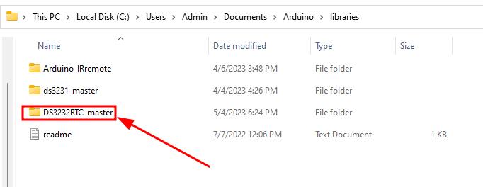
I downloaded the ds3231 RTC module library in arduino. The link is here.
To add the library in IDE I moved the downloaded folder in the libraries under Arduino IDE.
I learned how to programme DS32331 real time clock module. The RTC module is completely new for me I need to begin with lots of tutorials. I referred this link.
DS3231 - It has DS3231 chip which is extremely accurate - It works agt low power () - has built in temperature sensor - To store time and date inside it’s memory it has 24c32 EEPROM - has rechargeable battery to keep track of time when power is disconnected. - Communicates over I2C
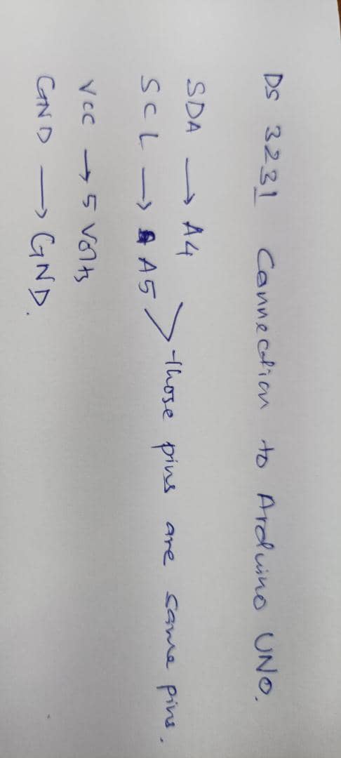
Connections
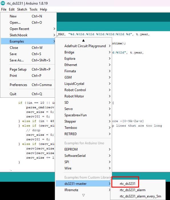
I used the example code to programme and did serial monitor and it worked. But I couldn’t change the time and date to current one.
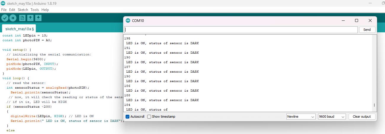
I wanted to let the LED glow when there is darkness. For this I decided to use LDR sensor. I did a LDR sensor test in arduino and now I added it in board design. This is the code I used to test LDR sensor on Arduino and did a serial monitor.
    const int LEDpin = 13;
    const int photoPIN = A0;

    void setup() {
    // initializing the serial communication:
    Serial.begin(9600);
    pinMode(photoPIN, INPUT);
    pinMode(LEDpin, OUTPUT);
    }
    void loop() {
    // read the sensor:
    int sensorStatus = analogRead(photoPIN);
        Serial.println(sensorStatus);
    // now, it will check the reading or status of the sensor is < 200
    // if it is, LED will be HIGH
    if (sensorStatus <200)
    {
        digitalWrite(LEDpin, HIGH); // LED is ON
        Serial.println(" LED is ON, status of sensor is DARK");
    }
    else
    {
        digitalWrite(LEDpin, LOW);
        Serial.println(" ***************");
    }
    }
For my project I need to drive multiple servo. For now I will drive servo with arduino using milli functions as it is something new for me. For this I checked this tutorial. I gave the clock timing. Servo 1 drives at every second and servo 2 drives at every one minute and it worked for now.
Code I used is here
    #include <Servo.h>

    Servo hourServo;
    Servo minuteServo;
    Servo secondServo;

    const int hourHandPin = 9;    // Pin for the hour hand servo
    const int minuteHandPin = 8; // Pin for the minute hand servo
    const int secondHandPin = 7; // Pin for the second hand servo

    const int hourOffset = 90;    // Offset angle for the hour hand (adjust as needed)
    const int minuteOffset = 90;  // Offset angle for the minute hand (adjust as needed)
    const int secondOffset = 90;  // Offset angle for the second hand (adjust as needed)

    void setup() {
    hourServo.attach(hourHandPin);     // Connect hour hand servo to pin 9
    minuteServo.attach(minuteHandPin); // Connect minute hand servo to pin 10
    secondServo.attach(secondHandPin); // Connect second hand servo to pin 11
    }

    void loop() {
    // Get current time
    unsigned long currentTime = millis();
    unsigned long seconds = currentTime / 1000;
    unsigned long minutes = seconds / 60;
    unsigned long hours = minutes / 60;

    // Calculate angles for the servo motors
    int secondAngle = (seconds % 60) * 6;  // 6 degrees per second
    int minuteAngle = (minutes % 60) * 6;  // 6 degrees per minute
    int hourAngle = ((hours % 12) * 30) + ((minutes % 60) / 2);  // 30 degrees per hour, 0.5 degrees per minute

    // Set servo angles
    hourServo.write(hourAngle + hourOffset);
    minuteServo.write(minuteAngle + minuteOffset);
    secondServo.write(secondAngle + secondOffset);

    delay(1000);  // Update the clock every second
    }
Testing LED board
To test the led board I uploaded the blink example code from IDE and it worked.
Then tested the led strip controlled by relay and it worked. The code is same as blink led code example. I replaced blink led pin to the relay pin.
    void setup() {
    pinMode(8, OUTPUT);
    }

    void loop() {
    digitalWrite(8, HIGH);
    delay(1000);
    digitalWrite(8, LOW);
    delay(1000);
    }
LDR Testing
I want to use the white mono colour LED and which is of 12V. Since from my board I can provide only 5V I used external supply to LED and connected to the relay.
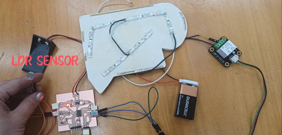
On my board I connected LDR sensor to PA6(2) which is photoPin and I defined the relay pin in place of LEDpin. I referred this and uploaded the code below and it worked.
const int LEDpin = 8;
    const int photoPIN = 2;

    void setup() {
    // initializing the serial communication:
    Serial.begin(9600);
    pinMode(photoPIN, INPUT);
    pinMode(LEDpin, OUTPUT);
    }
    void loop() {
    // read the sensor:
    int sensorStatus = analogRead(photoPIN);
        Serial.println(sensorStatus);
    // now, it will check the reading or status of the sensor is > 200
    // if it is, LED will be HIGH
    if (sensorStatus >200)
    {
        digitalWrite(LEDpin, HIGH); // LED is ON
        Serial.println(" LED is ON, status of sensor is DARK");
    }
    else
    {
        digitalWrite(LEDpin, LOW);
        Serial.println(" ***************");
    }
    }
Testing mechanism using arduino Mega
Since the board I was not working I used arduino mega to test the mechanical part. I connected all three servos to the PWM pins (2,3,6). I moved the servo one by one and tested all together
I uploaded the example sweep code from Arduino IDE.
#include <Servo.h>

Servo Servo;  // create servo object to control a servo


int pos = 90;    // variable to store the initial servo position

void setup() {
Servo.attach(2);  // attaches the servo on pin 2 to the servo object
}

void loop() {

Servo.write(70);            // tell servo to go rotate CW @ fulll speed
delay(2000);                     // waits 2seconds
Servo.write(180);           // tell servo to go to rotate CCW @ full speed
delay(500);                // waits 500 ms
Servo.write(90);              // tell servo to stop rotating
delay(3000);                       // waits 3seconds
}
Testing all servos together.
In the same example code I added the servo object as I have three servos.
#include <Servo.h>

Servo ServoMonth;  // create servo object to control a servo
Servo ServoDate;  // create servo object to control a servo
Servo ServoDay;  // create servo object to control a servo
// twelve servo objects can be created on most boards

int pos = 90;    // variable to store the initial servo position

void setup() {
ServoMonth.attach(4);  // attaches the servo on pin 2 to the servo object
ServoDate.attach(2);  // attaches the servo on pin 2 to the servo object
ServoDay.attach(3);  // attaches the servo on pin 2 to the servo object
}

void loop() {

//  ServoMonth.write(70);              // tell servo to go rotate CW @ fulll speed
//  delay(500);                       // waits 2seconds
//  //   ServoMonth.write(180);              // tell servo to go to rotate CCW @ full speed
//  //    delay(500);                       // waits 500 ms
//  ServoMonth.write(90);              // tell servo to stop rotating
//  delay(2000);                       // waits 3seconds

ServoDate.write(70);              // tell servo to go rotate CW @ fulll speed
delay(500);                       // waits 2seconds
//    ServoDate.write(180);              // tell servo to go to rotate CCW @ full speed
//    delay(500);                       // waits 500 ms
ServoDate.write(90);              // tell servo to stop rotating
delay(2000);                       // waits 3seconds

ServoDay.write(70);              // tell servo to go rotate CW @ fulll speed
delay(500);                       // waits 2seconds
//    ServoDay.write(180);              // tell servo to go to rotate CCW @ full speed
//    delay(500);                       // waits 500 ms
ServoDay.write(90);              // tell servo to stop rotating
delay(2000);                       // waits 3seconds
}
Testing my servo board.
I uploaded the code as below.
- Select the board
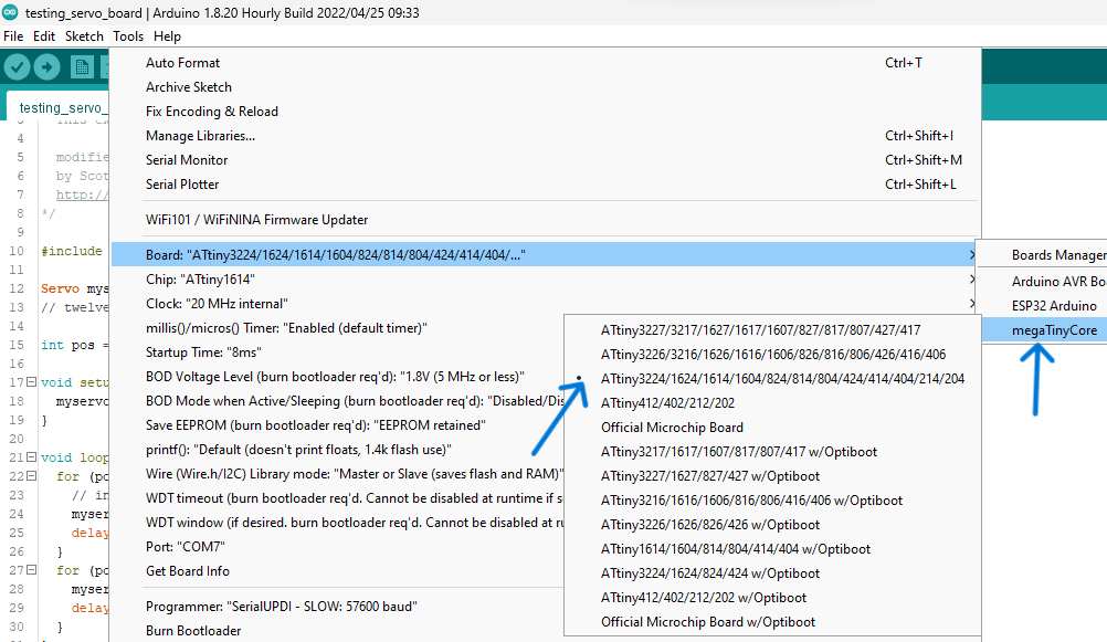
-
Select the chip
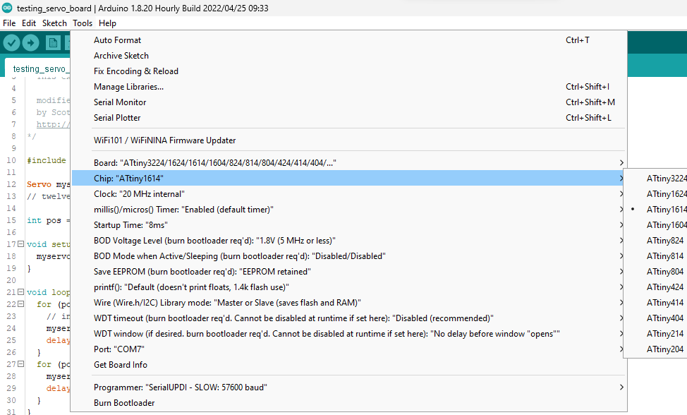
-
Select the programmer
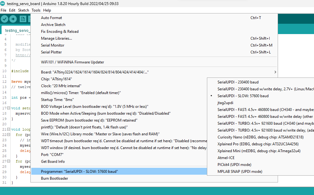
-
Select the port
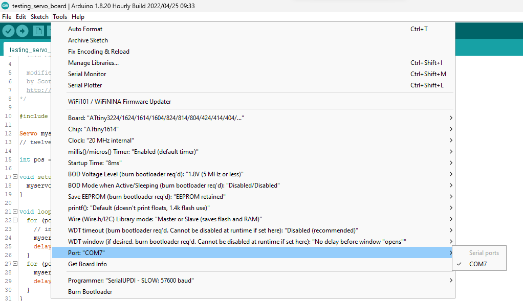
-
Compile and verify the code
- Upload the code.
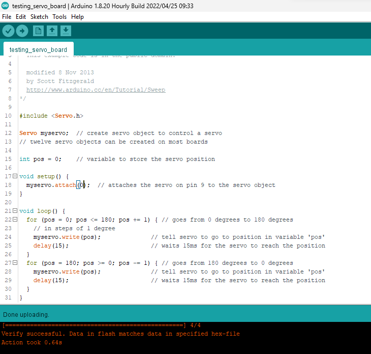
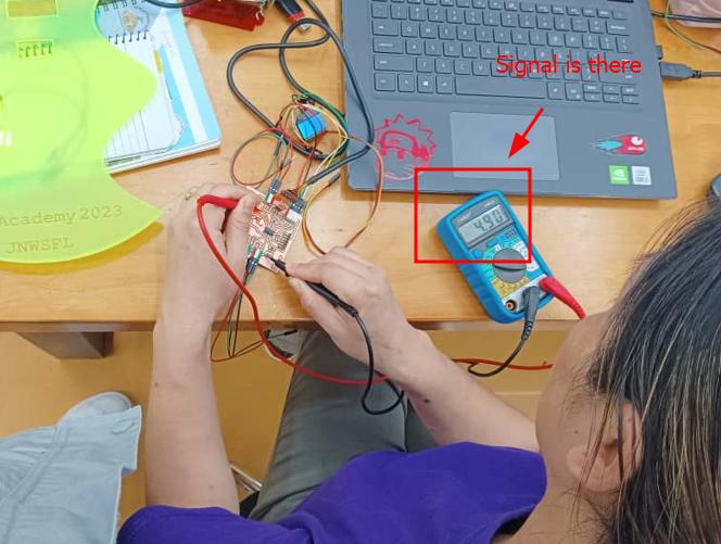
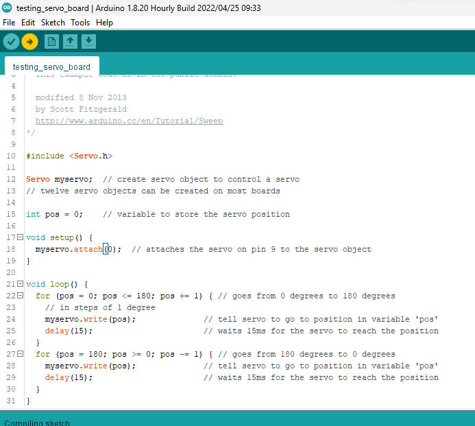
Guru Rico helped me with codding to test the board with the following code and it worked. For this I did not use servo motors instead I used multimeter to see the signal lines and it worked. In the signal lines it shows 4.9V when the signal is passing.
    // Yeshey Wangmo's FP board pin test program

    // by Yeshey Wangmo & Rico Kanthatham, Fab Academy 2023, Bhutan


    #include <Servo.h>

    Servo myservo;

    // Variables to represent all INPUT and OUTPUT pins on the Final Project Board
    int ledPIN = 3;
    int servo1 = 0;
    int servo2 = 1;
    int servo3 = 10;
    int sclPin = 7;
    int sdaPin = 6;
    int pos = 0;

    // the setup function runs once when you press reset or power the board
    void setup() {
    Serial.begin(9600);

    pinMode(ledPIN, OUTPUT);

    myservo.attach(servo1);
    }

    // the loop function runs over and over again forever
    void loop() {
    digitalWrite(ledPIN, HIGH);   // turn the LED on (HIGH is the voltage level)
    Serial.println("LED ON");
    delay(2000);                       // wait for a second
    digitalWrite(ledPIN, LOW);    // turn the LED off by making the voltage LOW
    Serial.println("LED OFF");
    delay(1000);                       // wait for a second

    //Use the code below to check if individual signal pins receiving 5V...change the name of the pin receive HIGH signal
    digitalWrite(servo3, HIGH);   // turn the LED on (HIGH is the voltage level)
    Serial.println("Pin ON");
    delay(3000);                       // wait for a second
    digitalWrite(servo3, LOW);    // turn the LED off by making the voltage LOW
    Serial.println("Pin OFF");
    delay(3000);                       // wait for a second

    //code for testing servo motion
    for (pos = 0; pos <= 180; pos += 1) { // goes from 0 degrees to 180 degrees
        // in steps of 1 degree
        myservo.write(pos);              // tell servo to go to position in variable 'pos'
        delay(15);                       // waits 15ms for the servo to reach the position
    }
    for (pos = 180; pos >= 0; pos -= 1) { // goes from 180 degrees to 0 degrees
        myservo.write(pos);              // tell servo to go to position in variable 'pos'
        delay(15);                       // waits 15ms for the servo to reach the position
    }
    }