Week 16. WildCard Week
We have seven heavy machineries as listed below: 1.Water jet 2.Wire EDM 3.TAI CNC 4.Track mill 5.CNC lathe 6.Zund 7.Shopbot
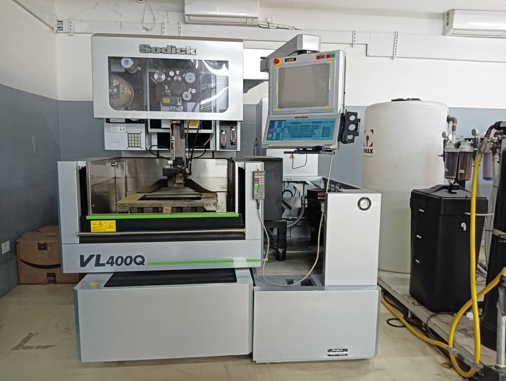
Wire EDM VL400Q
Safety measures:
- During the operation of wire EDM there wont be much noise or dust. We can use gloves to handle job piece only. Be careful with XYZ movement while using remote control.
This week I learned on operation of wire EDM(Electric Discharge Machine) in our lab.
-
Wire EDM is a electric discahrge machine which cuts the highly conductive metal like steel, brass and aluminium.
-
It works by creating an electrical discharge between the wire and the work piece(highly conductive metals).
-
The de-ionized water is used as a coolant as well as it washes away debris. De-ionized water is used because of its low viscosity and carbon free characteristics.
-
The maximum height of the job piece we can cut in the wire EDM VL400Q is 170x400x300(mm).
Advantage of using wire EDM
- It has high precision
- It has more accuracy in creating any shapes
- No surface damage on the job piece
- Less material waste
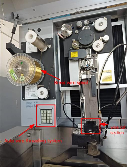
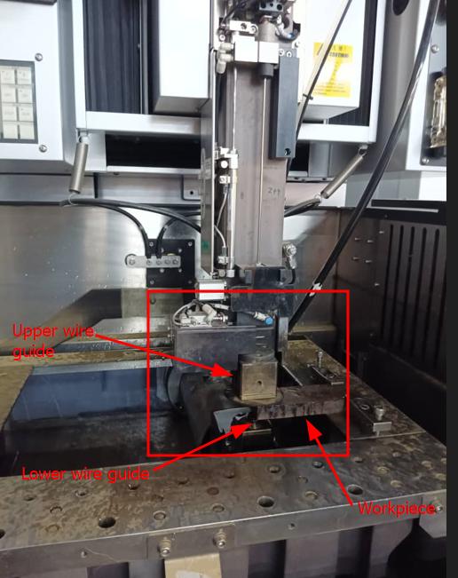
Machine parts
- Lower wire guide assembly
- Upper wire guide assembly
- Auto wire threading
- Flushing unit(High pressure & Low pressure)
- Chiller unit:Maintain water resistance and as a coolant
- Di-electric sections:Maintain the water temperature(20-24 deg)
- Control sections.
Types of operation
- Die cut
- Punch cut
- Open cut
- Tapper
Consumable Parts
- Brass wire
- Carbide(upper & lower)
- Wire guard
Wire alignment using verticle block
After doing maintenance in upper guide or doing tapper cut operation it is important to do vertical wire alignment.
- Go to Manual > prepare > verticle alignment
- Press [Manual button] for ” Verticle alignment
Press [X+],[X-],[Y+] OR [Y-]
-
Input the wire tension value (160 fpr 0.25mm wire). Press ENTER switch Cut Verticle Alignment block and notice the spark and adjust with [U+ & U-] and [V+ & V-] to get spark evenly from top to bottom.
-
Press OFF switch to stop and press ACK switch to remove the message.
Move coordinate
Select the move “option” select the coordinate (X or y) Keep ST and ABS ON Press ENTER
Note:For multi cavity use 54 & 59 coordinate
Different type of coordinate set
- Approach face
- Width center
- Corner finding
- Hole center
- Rndom 3 manual
- Random 3 auto
- Guage profile
- Manual tilt offset
- Auto tilt offset
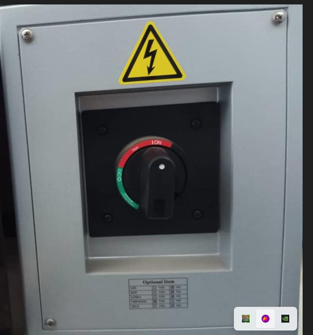
Machine operation step by step
- Turn ON MCB from the back side of machine
- Turn Source ON
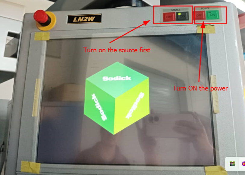
- Turn Power ON – There will be message displayed on screen to turn on power.
-
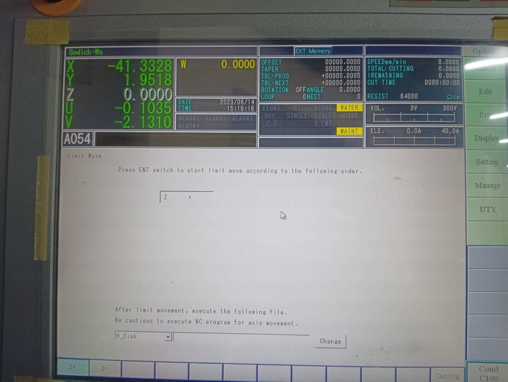
Press enter to move Z-axis to it’s upper limit(message will be given on screen)
-
To make UV 00 – Go to Manual >> MDI >> ENTER. This is to set UV coordinate zero. When turning OFF the power and source the UV coordinate usually get lost.
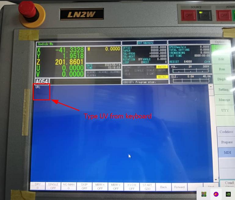
- Type “UV” and press enter.UV coordinate becomes 0.
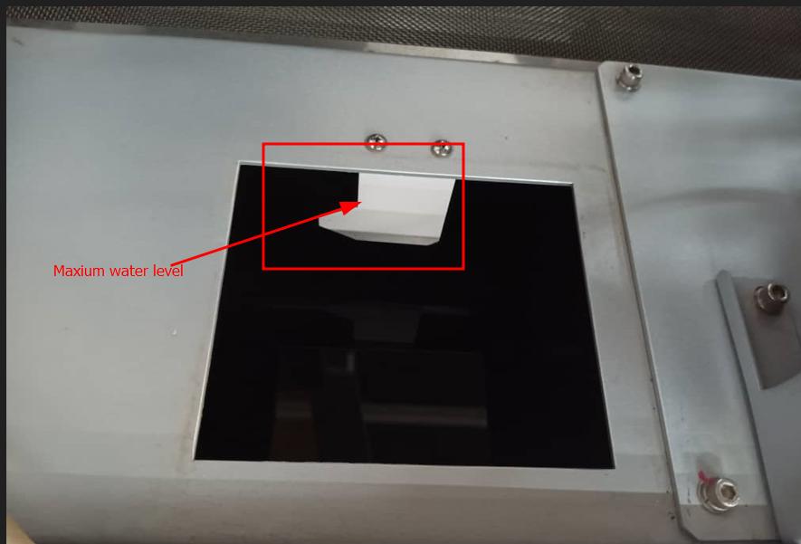
Important checks
- Check the water level
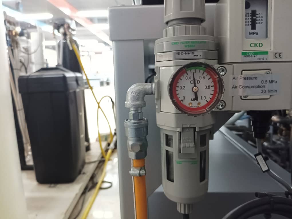
- Air pressure should be minimum 4 bar(4-5bar).
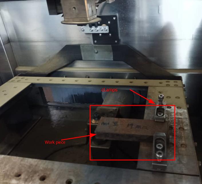
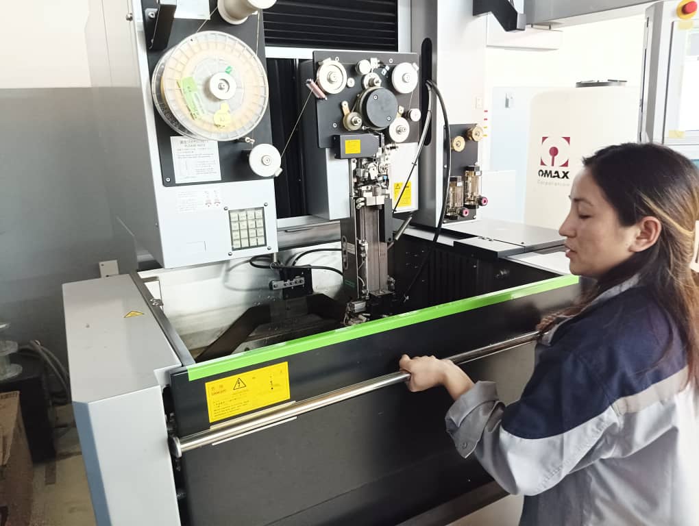
Clamping the job piece
I placed the job piece on the work table and clamped with bolts. I used 20mm thick MS plate as a workpiece.
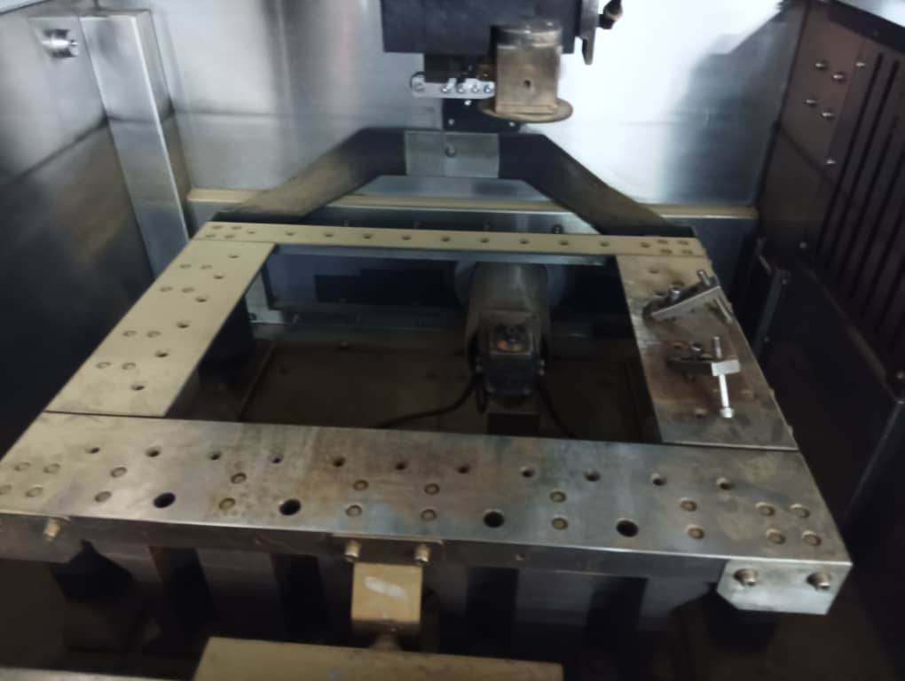
This is a work table to clamp the workpiece.
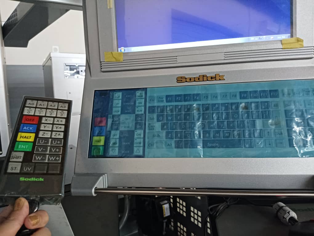
Use remote to move the machine to XYZ. Lock the UV and do not move it one the vertical alignment is done.
Machine speed:
It is confusing for the beginner when using remote and moving manually.
- 1=High speed
- 2=medium speed
- 3=slow speed
- 4=very slow
Coordinate setting
Firstly I set the machine XYZ coordinate to 0 from which the cutting begins.
To set the machine coordinate move the XY close to the work piece and keep it 1 or 2mm space and set the coordinate XY to Zero. If the wire touch the workpiece it will show ST on screen, do not touch wire to the workpiece.
After placing the wire closer to the workpiece followed the steps below.
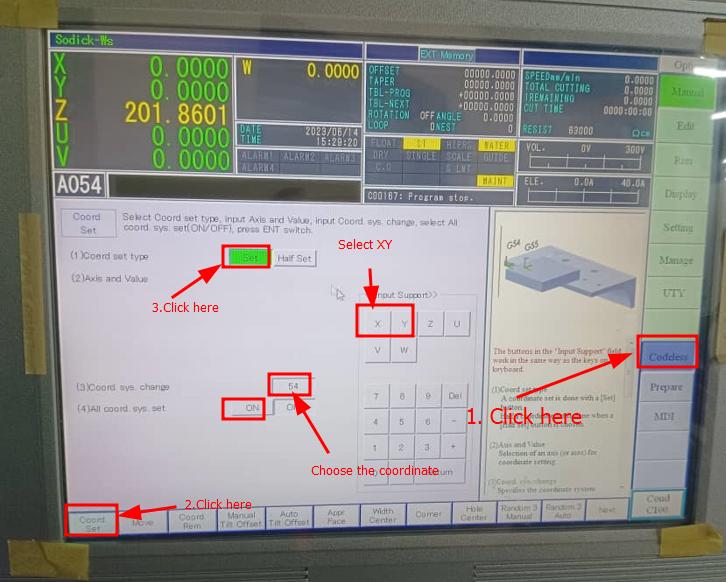
- Go to manual >> codeless >> click Coord set >>Select set >> select XY.
- Enter the coordinate that is going to be used. I used 54 & 55 and hit Enter from the key board.
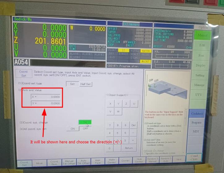
- For setting Z coordinate we need to drop the upper guide close to the job piece (keeping approximate distance of 1,2 mm from nozzle to surface of job). Select Z and enter 54 and 55 same as I did for XY.
I am using two coordinate because if i loose one coordinate I can use the other one.
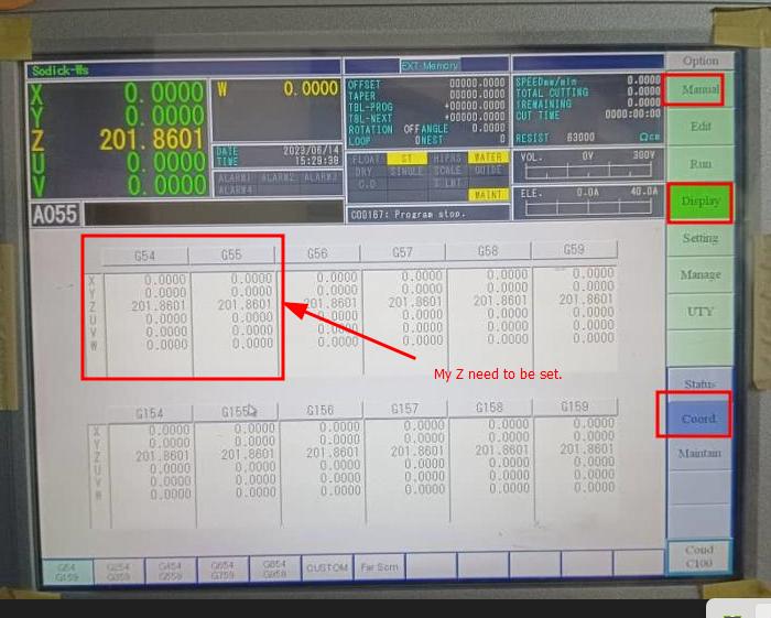
- Checking the coordinate: Go to manual >> coord >> display. here we can see if the coordinates are set to zero or not. Once it is set it will show 00 in all XYZUVW.
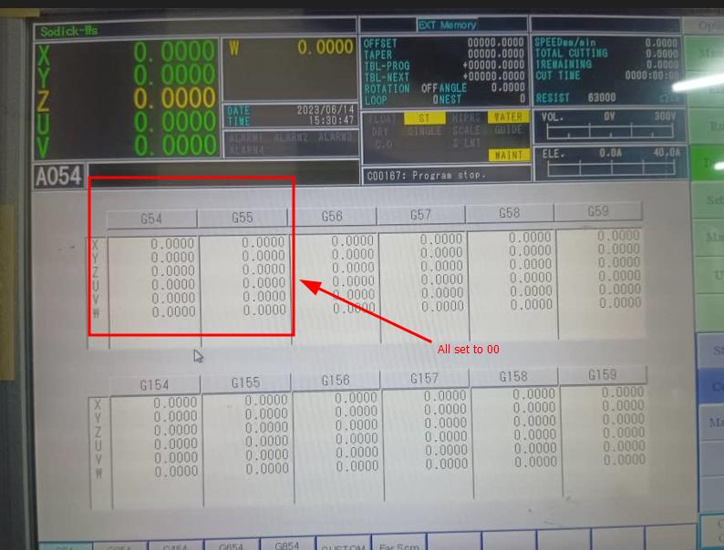
- Here is the picture of set coordinate for my workpiece.
- Close the front cover/shutter.
Loading the design file
How to import file from EXT memory
- File > open Uty>Drag the required file to Heart NC
- Click on UTY from right column option.
- From the bottom left corner click on file >> open
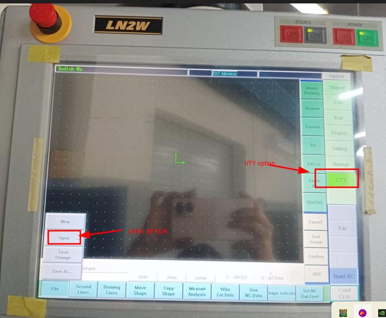
- Select the file to be cut and hit ok. The drawing gets loaded in screen.
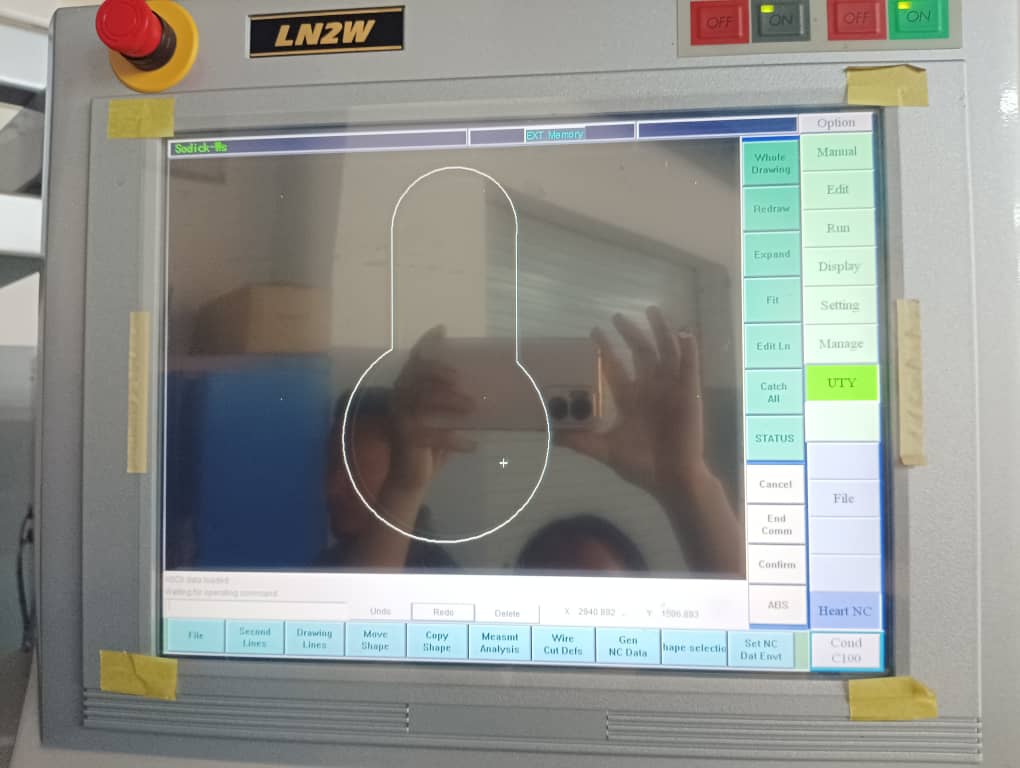
- I need to set the origin. To this firstly i need to create a point. Go to Drawing lines >> Points >> Arbit points.
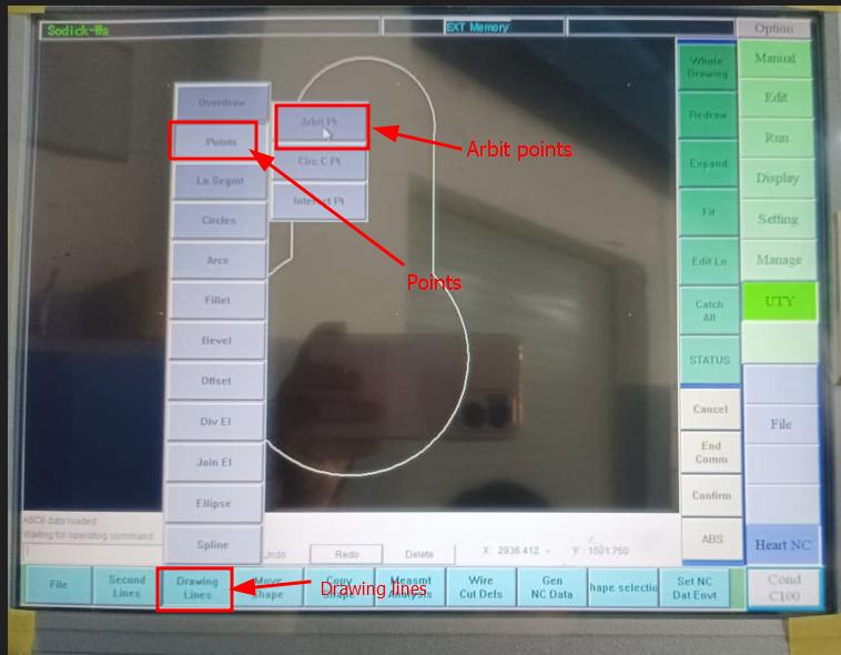
- To set origin go to status >> set origin >> click on the point. I placed the points where I want let the wire approach.
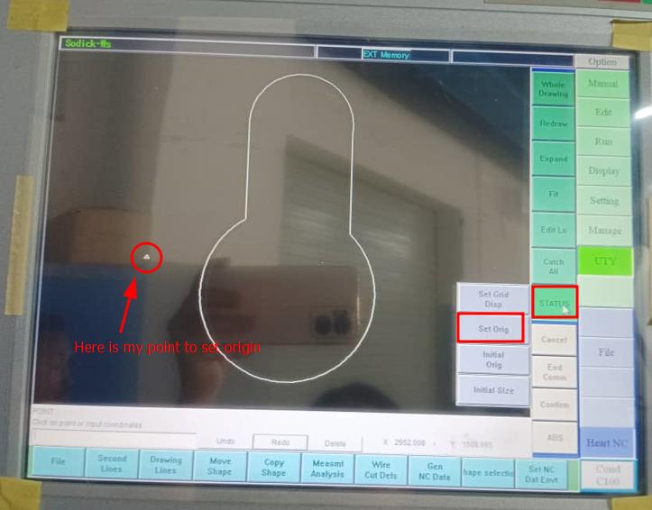
-
To select the type of cutting got to >> wire cut defs. >> select the punch cut(I will do punch cut).
-
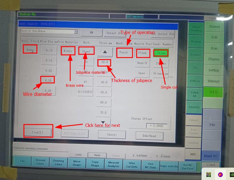
In window pop up set the parameters as per requirement and click ok.
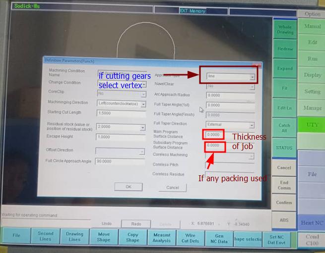
- When clicking OK the window pop up to set parameters as shown below. After setting parameters click on find F.
-
The message will be displayed asking to click on shape.
-
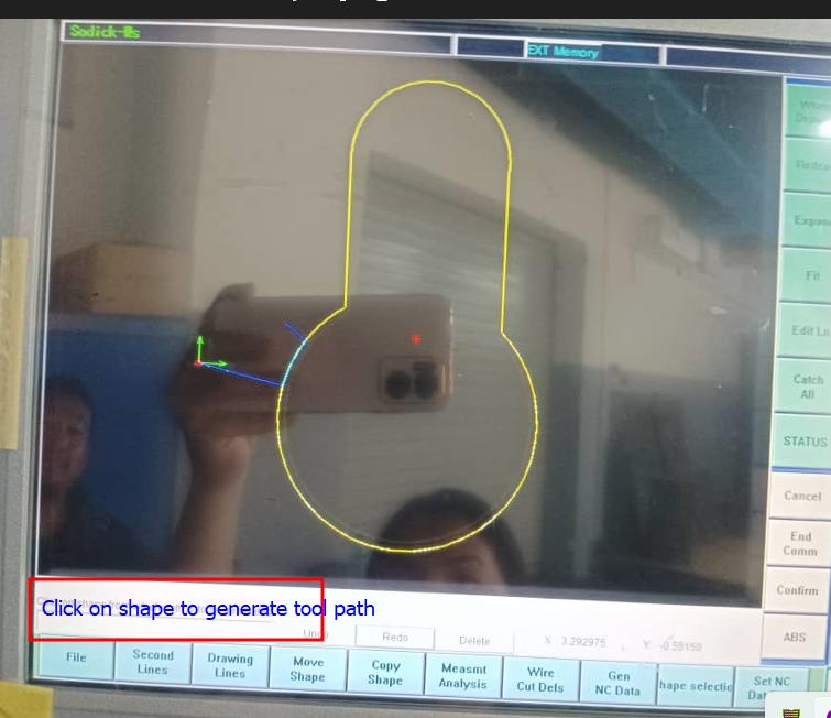
WHen clicking on shape the message displays saying to click on starting position or to input the coordinate to generate tool path. I clicked on my origin and the colour changed to purple.
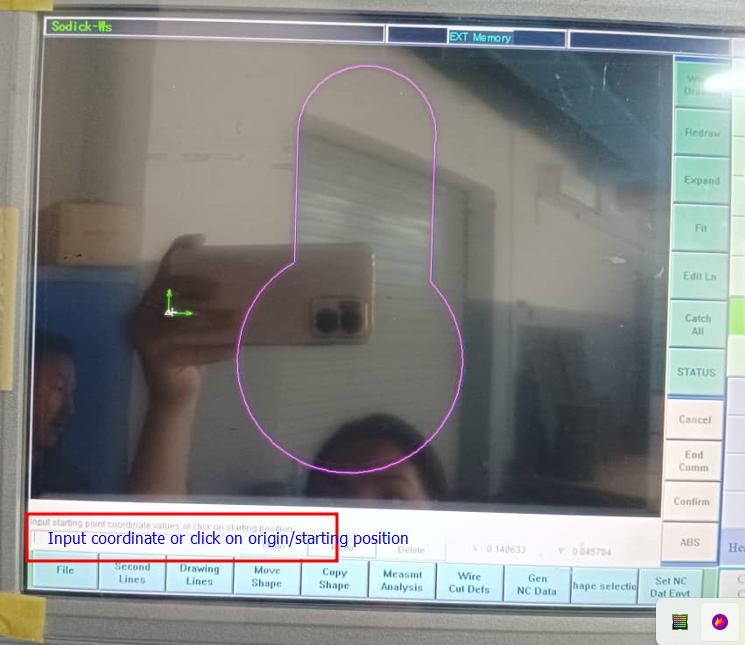
- Again the message will be displayed asking to click on shape. When clicking shape tool path gets generated as shown below.
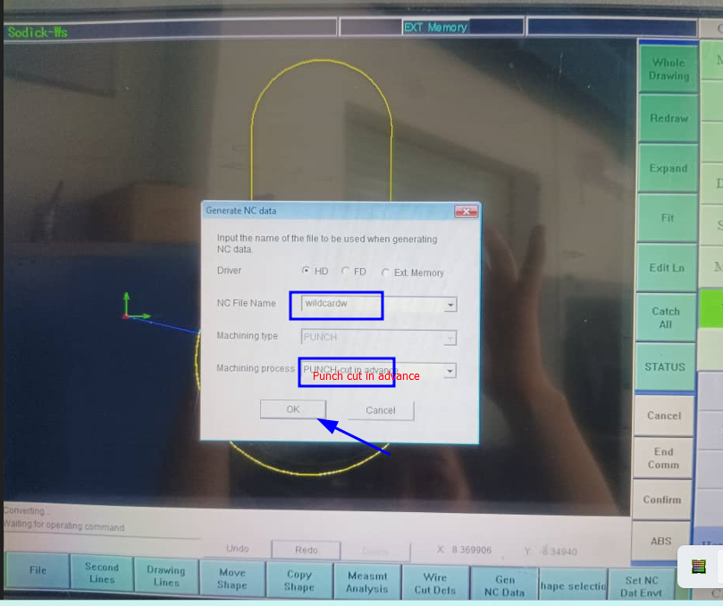
- Generating NC data: Go to GEN NC data option form bottom option and rename the file and select the select Punch cut in advance. Hit OK
- Go to Edit >> load >> select the file (wildcardw). I kept everything as it is and changed only the MAO value to 290 to prevent the wire breakage.
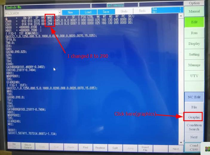
- click on Graphics >> from the bottom row options click on >> Draw >> Save.
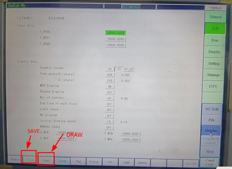
- The drawing apears and click on save.
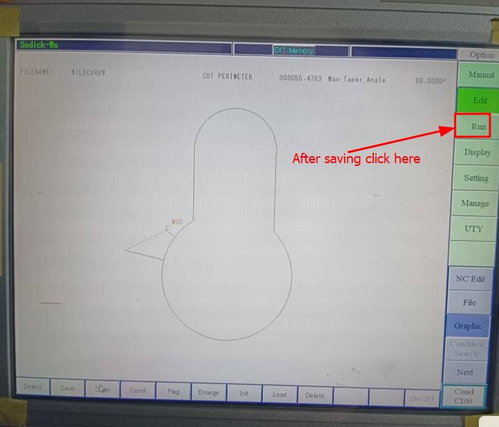
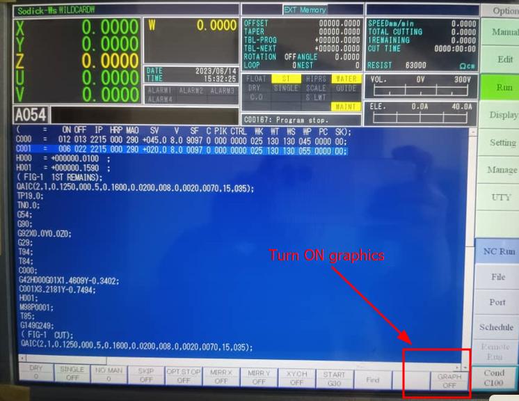
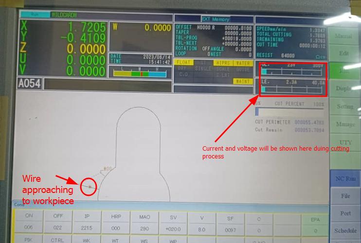
- Go to Run option from right column option. Turn on the graphics if it is off.
- if the graphics is on it eill be displayed as below.
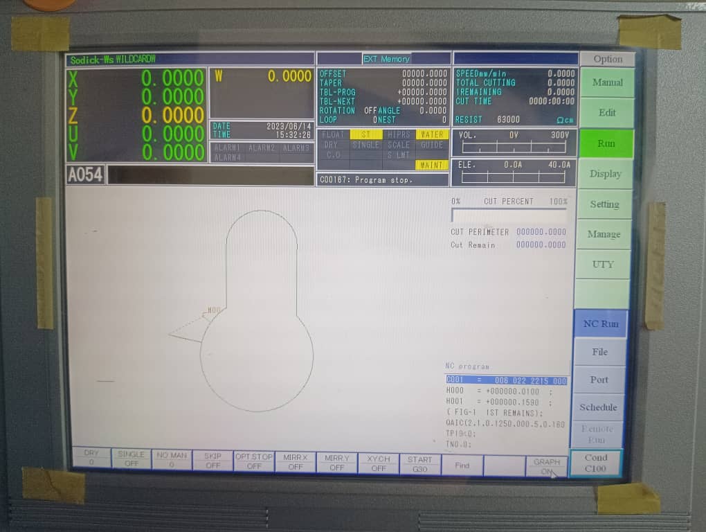
- Press HOME key from key board and press ENTER from keyboard. The cutting starts.
- Sometime the will be wire breakage due to many factors like low water resistivity, dirty water, low conductivity of metal, worn out carbide and high wire tension. When this happens there will be message on screen saying wire borken, auto threading performed. It automatically perform wire threading and resume the cutting.
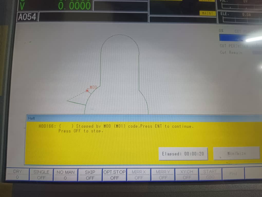
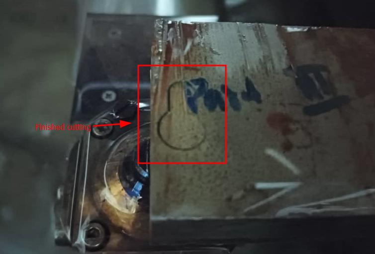
- When it reaches to M01 it stops by residual stock and give a beep sound and message will be given to continue or stop. We can press ENTER key to proceed.
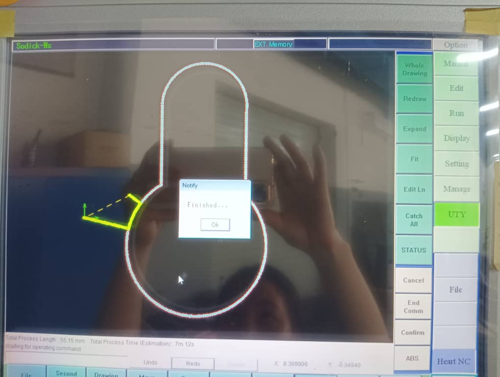
- When it finish cutting it will be shown as programme end on thr screen.
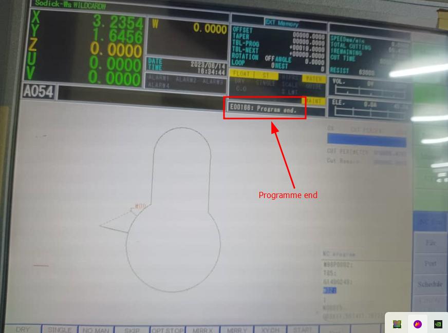
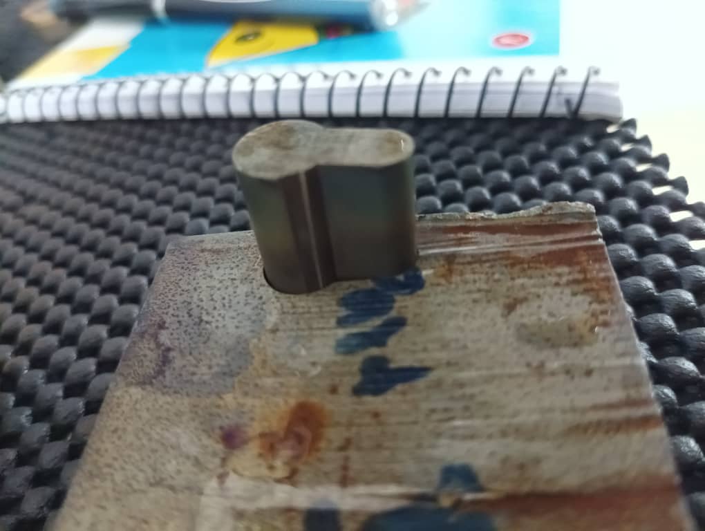
-
Cut the wire using Cut key from AWT section /keyboard. Raise the Z height and remove the job piece.
Dxf file is attached here