Questions & Answers
1. What will it do?
- My final project is named as Granny’s Calender because it will serve purpose for the elderly people like who do not know how to read English or do not know how to use phone.
- They can easily allocate the current date in local language.
- The main input is Real clock time module which will read the current date and time and give feedback to the MCU and move the servos showing the the current date and time. I also have the LDR sensor as another input device which will sense the light and put off the LED on the frame. During night time the LED will glow and anyone walking around can see the calender dates.
2. Who’s done what beforehand?
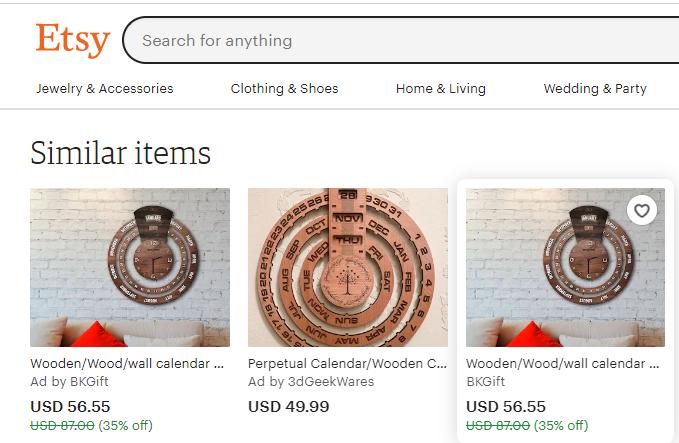
- Digital calenders are available many shopping sites and Pinterest but not available in our country.
-
In Ectsy site I have seen lots of perpetual calender as below.
-
In instructables I found he has made automatic perpetual calender so it is open source I started making one with our local language.
3. What will you design?
- Design the physical parts like support and frame using Fusion360 for cutting and CNC cutting .
- Design gears to laser cut.
- Design 3D printed brackets to hold rings.
- Design PCB boards for electronics using Kicad.
4. What materials and components will be used?
- For physical fabrication:
- 5mm thickness Plywood for rings and front cover
- Acrylic for reflecting the light
- Filament for printing the brackets.
- Bearings to hold the bracket
- M4 nuts and bolts to hold the brackets.
- 12mm hardwood as a stand to hold the rings.
- For Electronics board:
- Single sided copper board
- Attiny1614 as MCU
- LDR sensor
- Servo motors
- Relay
- LED
- wires
-
5. Where will it come from?
-
Most of the Electronics components are available in the lab except the 360 degree rotation servo motor I bought from Amazon.
- The plywood and the hardwood was bought from local market.
6. How much will they cost?
- The estimated cost are listed below:
| Part | Provider | Quantity | Price | Total |
|---|---|---|---|---|
| Plywood Sheet 600x300x3mm | JNW Super Fab lab | 1 | $ 10 | $10 |
| PLA Filament (grams) | jnw Super Fab lab | 300 | $ 0.1 | $ 30 |
| Servo Motor 360 degree | JNW Super Fab lab | 3 | $ 2 | $ 6 |
| 9V battery holder | JNW Super Fab lab | 1 | $ 1 | $ 1 |
| PCB - Copper Board | JNW Super Fab lab | 1 | $ 0.2 | $ 0.2 |
| MCU - Attiny1614 SMD | JNW Super Fab lab | 1 | $ 1 | $ 1 |
| Resistor - 10k SMD | JNW Super Fab lab | 1 | $ 0.05 | $ 0.05 |
| Resistor - 220 Ohm SMD | JNW Super Fab lab | 1 | $ 0.05 | $ 0.05 |
| Capacitor - 0.1uF SMD | JNW Super Fab lab | 2 | $ 0.3 | $ 0.6 |
| LED - 2V SMD | JNW Super Fab lab | 4 | $ 0.2 | $ 0.8 |
| Male header angle 2.54mm -1X6 | JNW Super Fab Lab | 2 | $ 1 | $ 2 |
| Male header angle 2.54mm -1X3 | JNW Super Fab Lab | 2 | $ 0.5 | $ 1 |
| Female header 2.54mm - 1X3 | JNW Super Fab Lab | 4 | $ 1 | $ 4 |
| Female header 2.54mm - 1X4 | JNW Super Fab Lab | 2 | $ 1 | $ 2 |
| Female header 2.54mm - 1X2 | JNW Super Fab Lab | 2 | $ 0.5 | $ 1 |
| Voltage regulator AMS1117 5.0 | JNW Super Fab Lab | 2 | $ 1 | $ 2 |
| Male to male jumper wires | JNW Super Fab Lab | 12 | $ 0.01 | $ 0.12 |
| Female to male jumper wires | JNW Super Fab Lab | 12 | $ 0.01 | $ 0.12 |
| Terminal block | JNW Super Fab Lab | 2 | $ 0.5 | $ 1 |
| 9V dracell battery | JNW Super Fab Lab | 3 | $ 1 | $ 3 |
| LDR sensor | JNW Super Fab Lab | 1 | $ 0.5 | $ 0.5 |
| LED strip | JNW Super Fab Lab | 1 | $ 2 | $ 2 |
| Total | $ 68.44 |
7. What parts and systems will be made?
- I designed the outer frame and gear and cut it using the laser cutter.
- I designed the back stand in Inkscape and made it in the shopbot.
- I designed the brackets in fusion360 and 3D print.
- Designed the PCB board and used SRM20 to mill and made PCB board.
8. What processes will be used?
- Laser cutting
- CNC shopbot cutting
- 3D printing
- PCB production
9. What questions need to be answered?
- Can the supplied voltage run the servos efficiently?
- Can servo pop up the date on exact angle?
- How to give sufficient power?
10. How will it be evaluated?
-
As per the listed criteria of final project, my project should incorporate subtractive and additive manufacturing process, electronics design and production, embedded microcontroller interfacing and programming, system integration and packaging.
-
The calendar frame I used CNC router to cut the stand and for the rings and bigger gears I used the laser cutter, thus fulfilling the subtractive process.
- The small drive gear and the base of servo motors are 3D printed and hence fulfilling the additive method.
- The main input device is Real time clock module for setting the current date and giving feedback ot the MCU and moves the servo the shoe the current date.
- The other input is LDR sensor to sense the light and turns LED on window ON at night.
- The servo motors and the LED are my output.
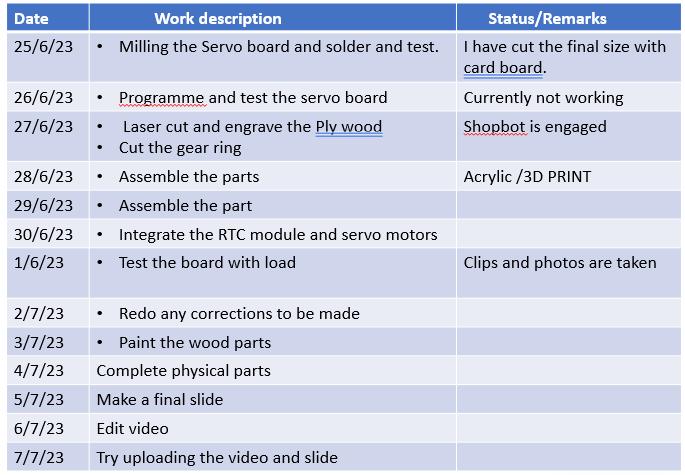
My schedule from now till the final day