05.3D Scanning and Printing
# Week 05. 3D Scanning and Printing
This week I demonstrated additive manufacturing using 3D printer and examined in deeper on the additive manufacturing process.
3D Printing
- 3D printing is a additive manufacturing process of making physical objects forming the physical object layer by layer without removal of material like carving and machining process.
- The object is formed by melting a material called filament and extruding out from nozzle depositing it on the bed layer by layer.
-
3D printing is applicable in various field like product design, medical devices, prototyping ideas and many more. 3D printing include the following procedures:
-
Firstly creating a 3D model.We can use any CAD(Computer Aided Design) softwares or we can scan the existing 3D object.<
- Slicing: Converting 3D design model into G-code. This step is important because 3D model consist of layers and for the printer to create each layer during printing process the instruction is required for the machine. Therefore the slicer software generates these instructions for the machine.
- Based on the instruction generated by the slicer software the printer builds the object we designed.
Assignments
-
Group Assignment:
- Test the design rules for your 3D printers.
-
Individual assignment:
- design and 3D print an object that could not made it subtractive process.
- 3D scan an object(and optionally print it)
Link to the group Assignment is here
The assignment of this week was to design and print an object which cannot be made by subtractive method of manufacturing like using CNC machines. This allow us to realize on that what makes the additive manufacturing process preferable than subtractive manufacture. It allows us rapid prototyping the ideas and also produces little waste compared to subtractive manufacture. 3D printing works well for complex and intricate designs. But it has some limitations like making over hangs where we have to use support materials. To know more on it’s limitations we did a group assignment ton design rules.
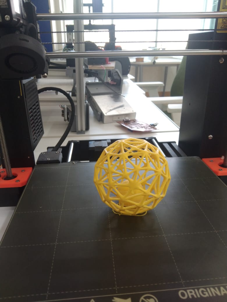
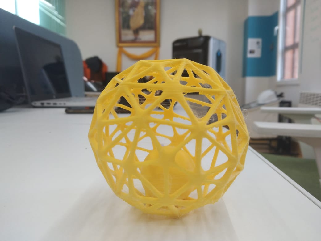
Taking advantage on capabilities of 3D printers I designed a ball with pipe. I saw a toy in my baby’s basket and I wanted print it out in our lab. I went through youtube working with various patterns in Fusion360. The link for the tutorial I referred here.
CAD Modeling
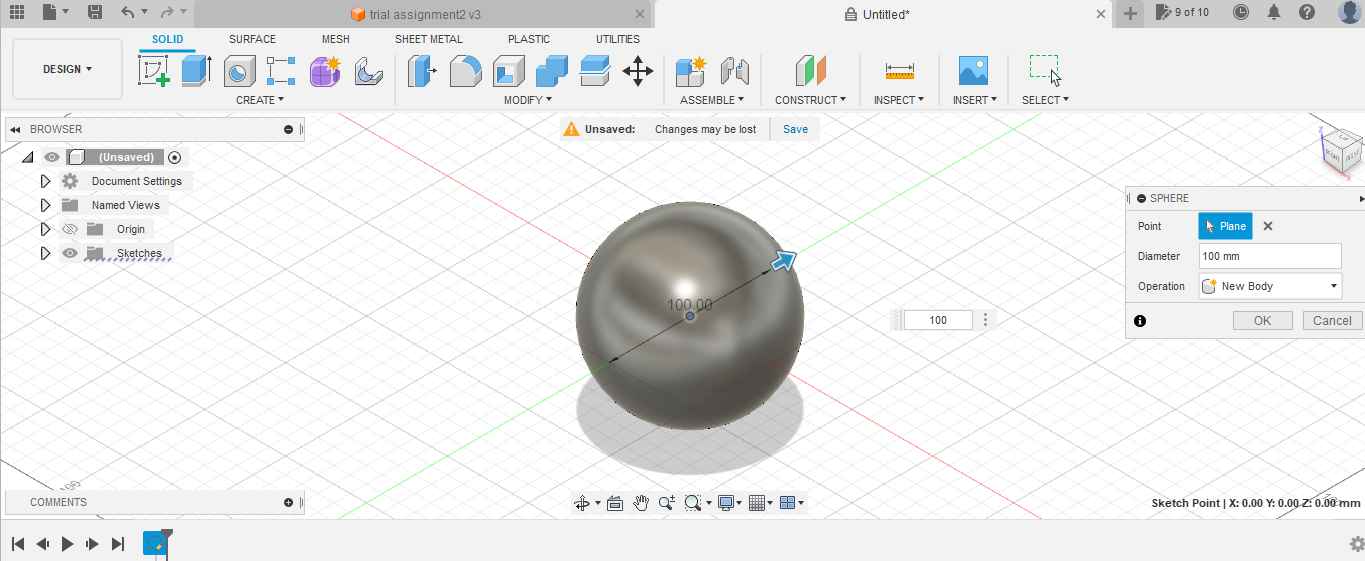
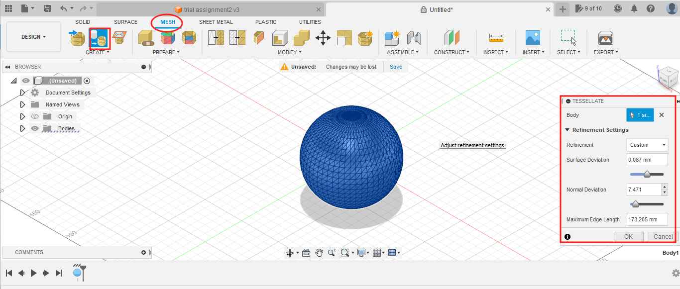
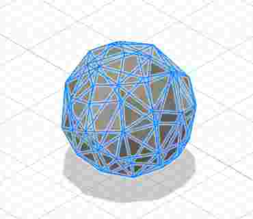
- I selected sphere to start the design and given the diameter 100mm. I used the mesh features to create the mesh body. Under the mesh option select tessellate. In the dialogue box I marked on preview to see the changes I am making. I adjusted the refining setting to which that looks good to me and thn clicked ok.
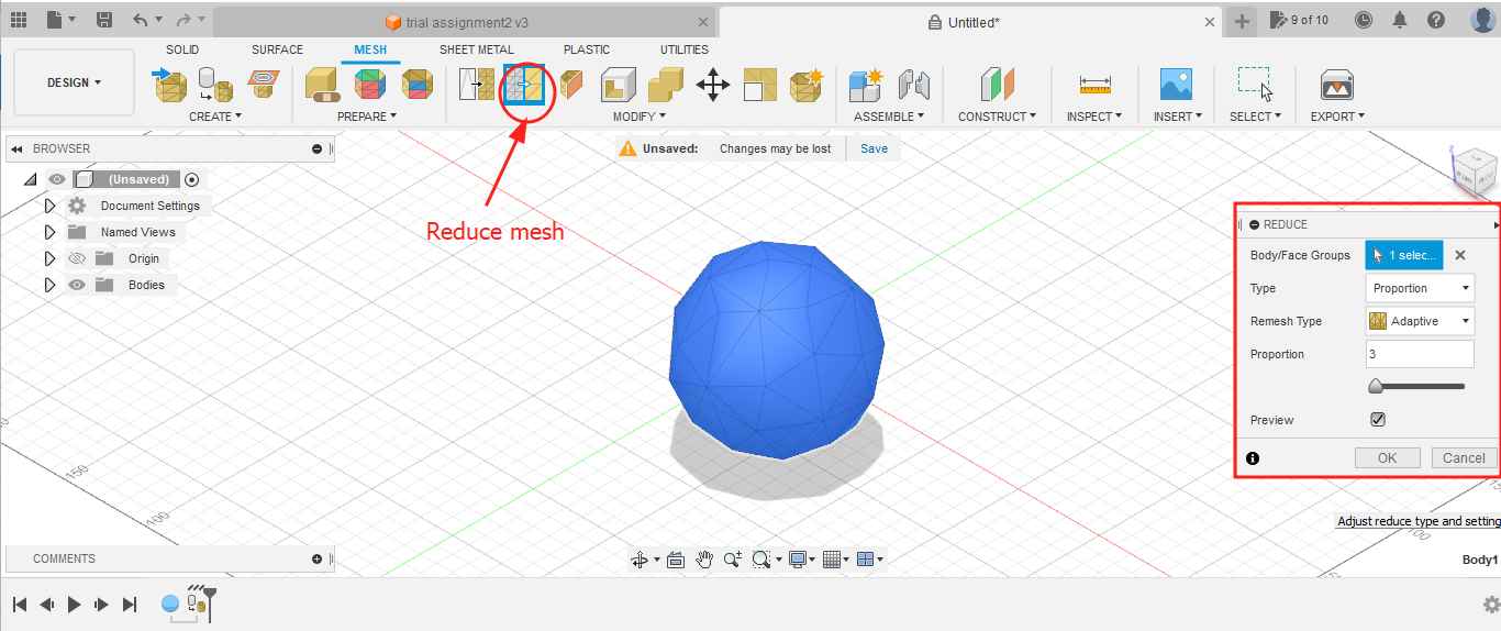
- To reduce the number of faces I selected the reduce option under modify drop down list. I kept proportion as 3 and clicked ok.
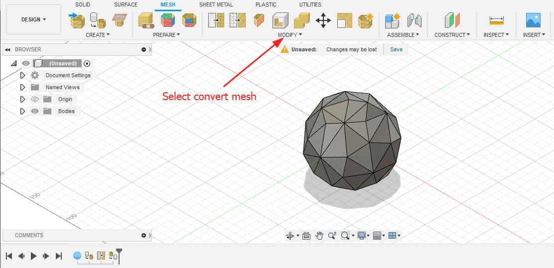
- Now I wanted to convert body into mesh. Under Modify drop down list I selected the Convert mesh option anD selected the body, kept operation as parametric and selected method as Faceted and hit OK.
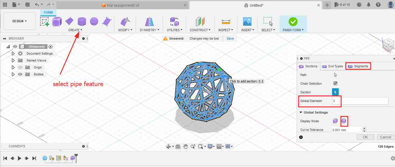
- Go back to Solid menu and under select option click on select priority> select edge priority.Again go back to select drop down list under selection filters click select through. Then i selected the whole body in which I can see only the edges got selected. Here I want to apply the pipe feature on edges.
-
Select the create Form feature and in drop menu select pipe. In dialogue box I kept global diameter to 3mm and global setting as smooth display. Under segment section I adjusted the density and clicked ok. !
-
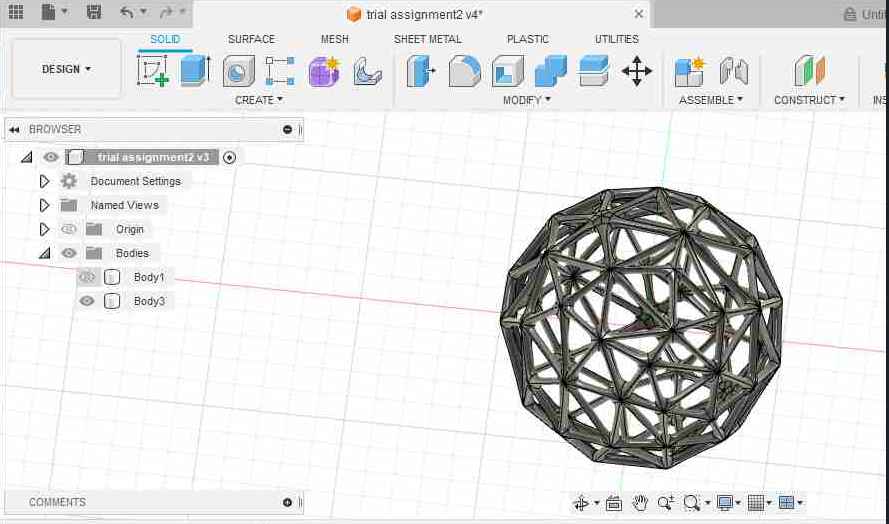
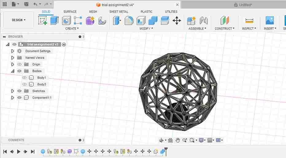
Hide the old body and view only the new body formed. I wanted to try printing a ball inside so I added inside and combined the object. Finally I exported the for in STL format for 3D print.
Processing for 3D printing
-
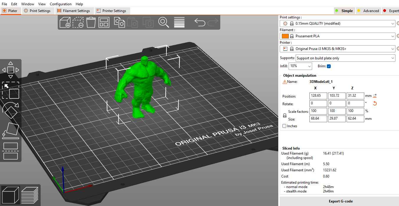
I need to prepare the STL file for 3D printing once I am done with file export and to do this I used open source slicing software called Prusa Slicer. It converts 3D models into layers which generating G-code which directs the printer.
-
I imported the STL file in slicer as shown below. To do mt print setting I kept the nozzle layer height to 0.15mm and infill at 10&. I didn’t give a support but gave brim to give good support in base formation. I selected the filament as Prusament PLA as it is commonly used in our lab. When I click on Slice Now it shows the used filament in grams and the the print time.
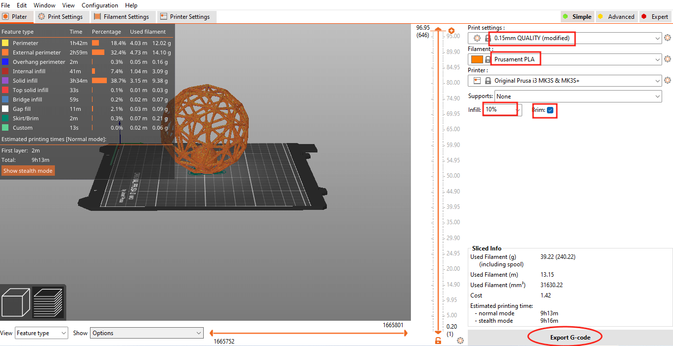
- We can also drag and view layer mode and inspect the print at every stage and it allow us to add color change to the print.

- Finally I exported the g-code by clicking on Export G-code to the SD card that goes to the Printer.
3D Printing
-
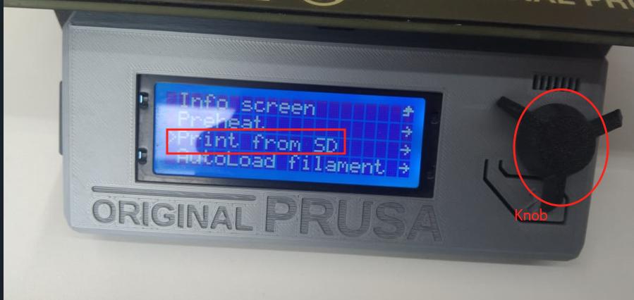
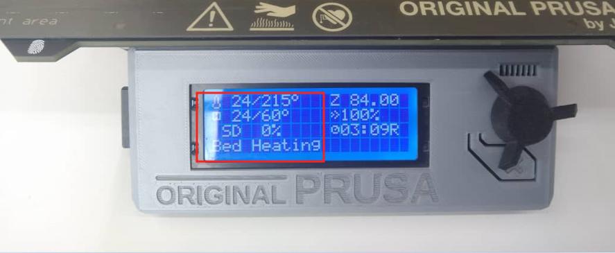
Load the filament to the printer by clicking to >Auto-load Filament on the printer screen and selection is done by pressing the knob. The printer heats up the nozzle and the bed upto the temperature to melt the PLA filament as I am using PLA.
-
From the SD card I selected my file to be printed by scrolling down using knob and the machine starts heating the bed and then print starts.
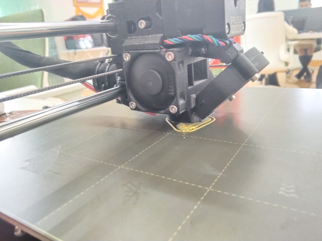
- Finally here is my finished print.
Getting started with Solid works
I also wanted try using Solid works because I found it interesting while creating patterns and easier regarding mirroring feature. Unfortunately it couldn’t support by my computer and I used on my friends computer where it is already installed.
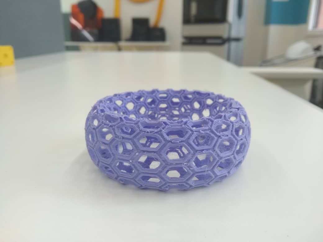
I actually wanted to make a bracelet with honey comb pattern around. I followed the tutorial video to create this honey comb pattern.
Steps I followed: - Firstly I created a new file and it is given a option to choose as Part, Assemble and Drawings. I selected as a part and saved the file. Before starting sketch I have to select the plane so I selected as front plane.
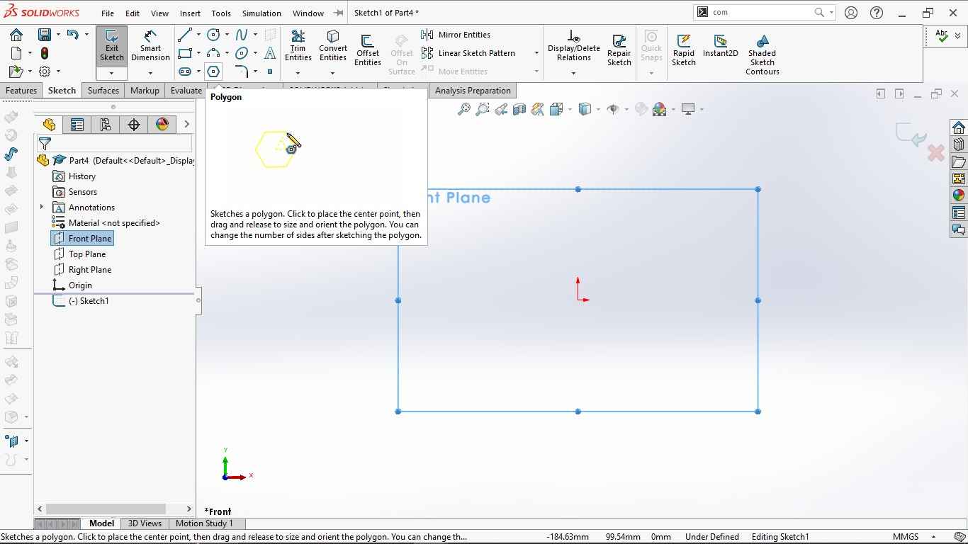
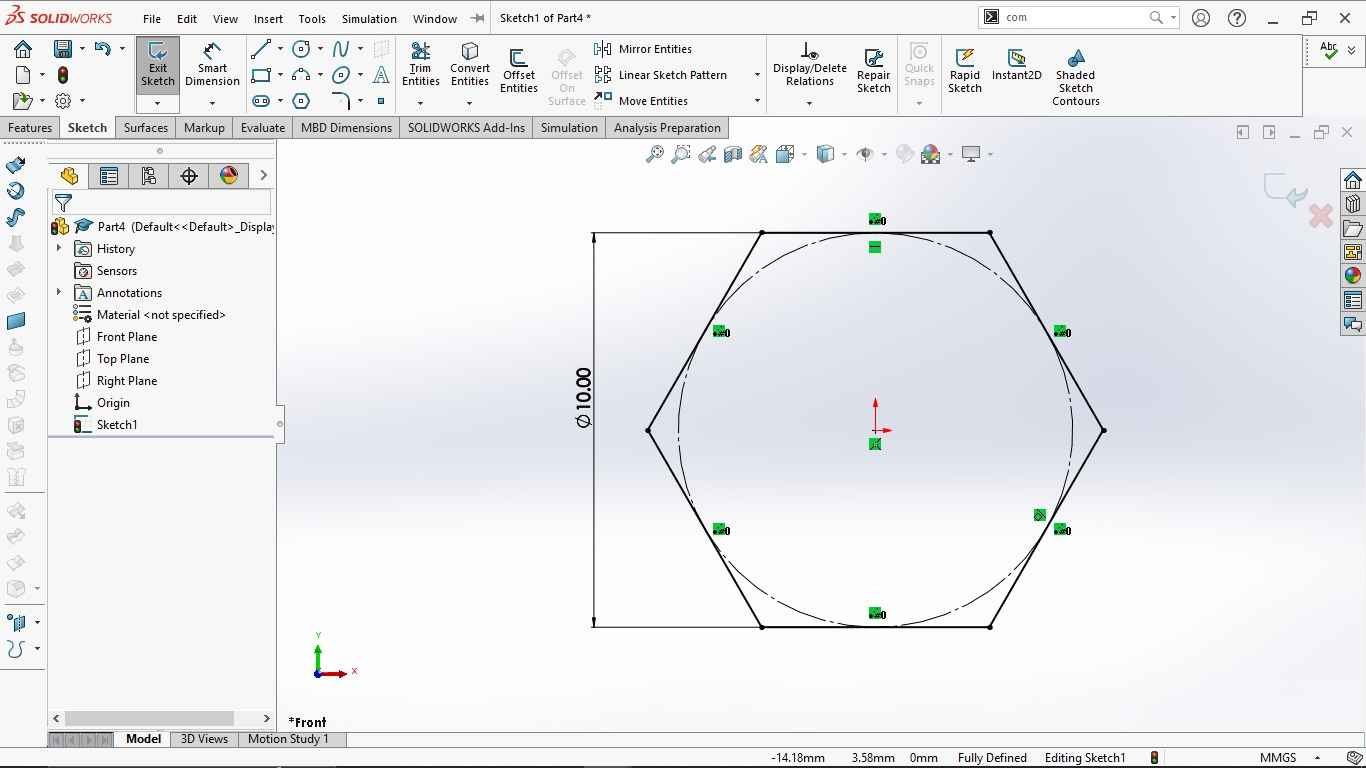
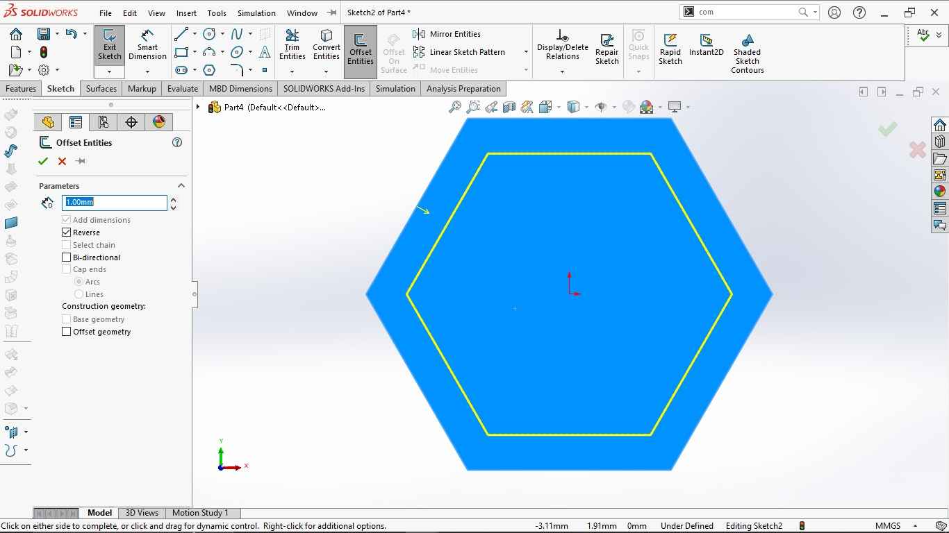
- To start sketch I selected sketch option >> selected polygon and then I defined the dimension and kept the inner circle to 10mm.
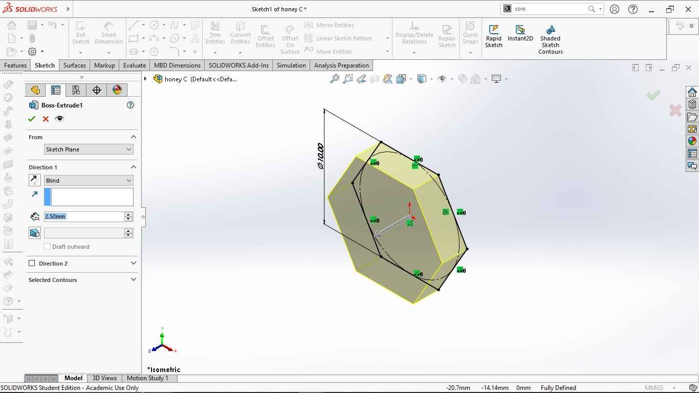
- Then I extruded the hexagon to 2.5mm using the extrude bose feature. To make hollow inside hexagon I selected the face >> Offset it to 1mm reverse.
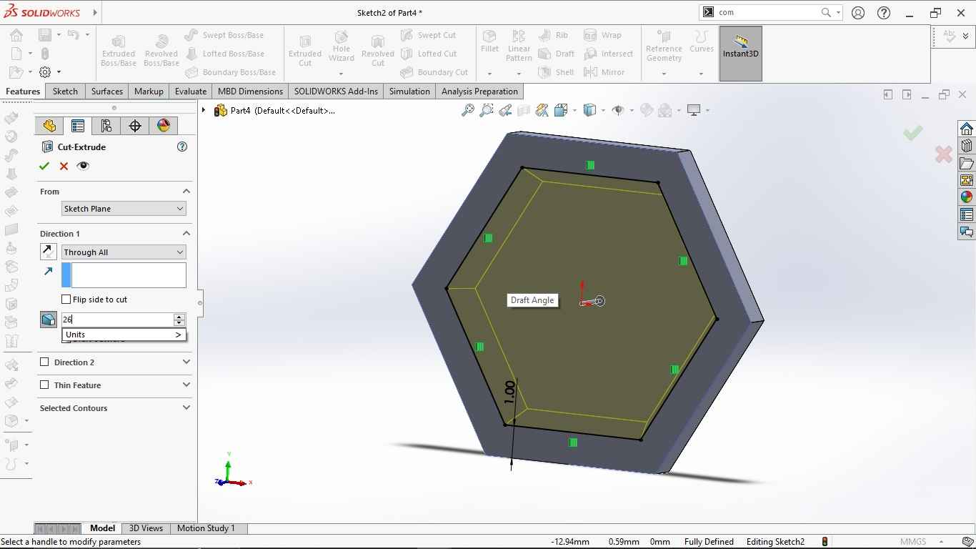
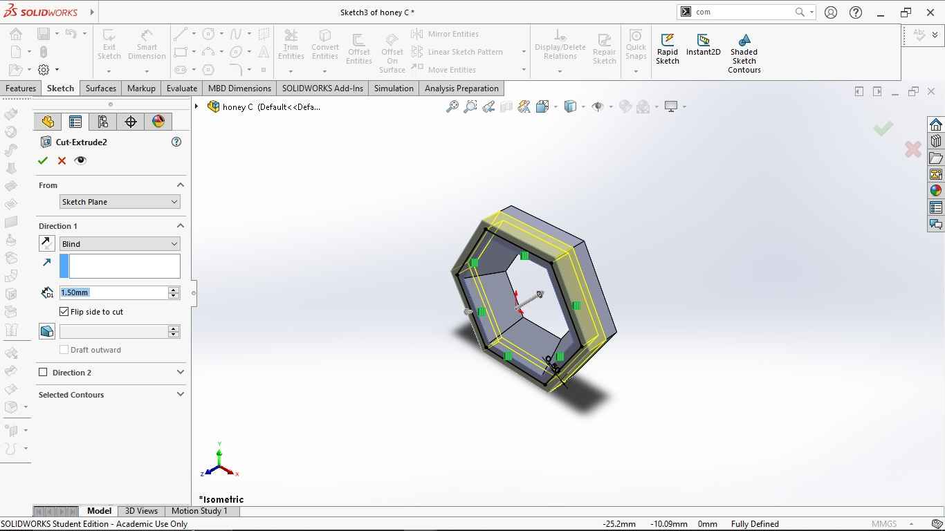
- To make a hollow inside I did extrude cut to 1mm depth at 25 degree angle.
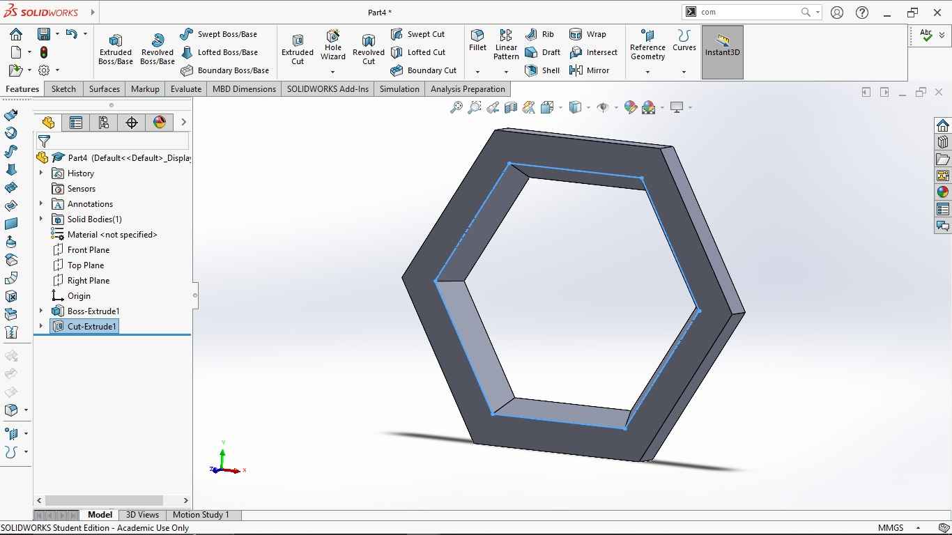
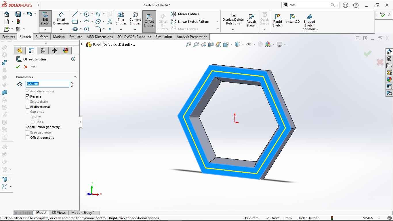
- To create the angle at the edges of hexagon >> selected offset entities to 0.5mm reverse and did extrude cut upto 1.5mm.
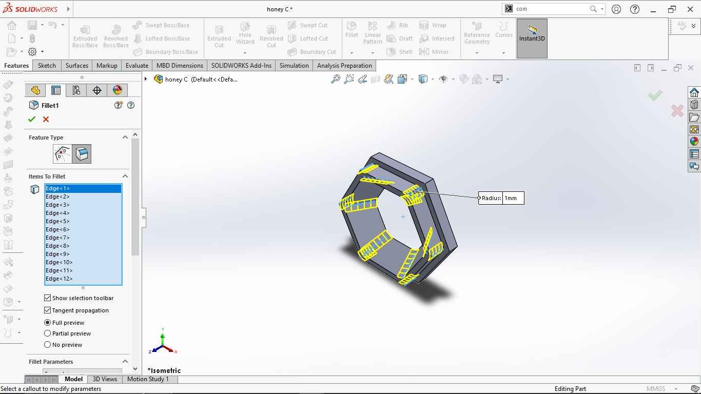
- I want to give a filament to the sharp edges. So I used the Fillet feature from Menu bar and selected all the edges and given the radius of 1mm.
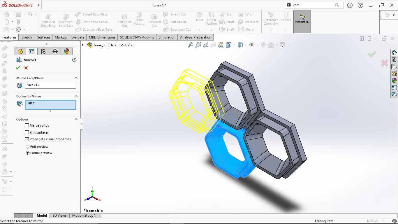
- I wanted the mirror the bodies. Selected Mirror >> selected the faces as a mirroring plane.
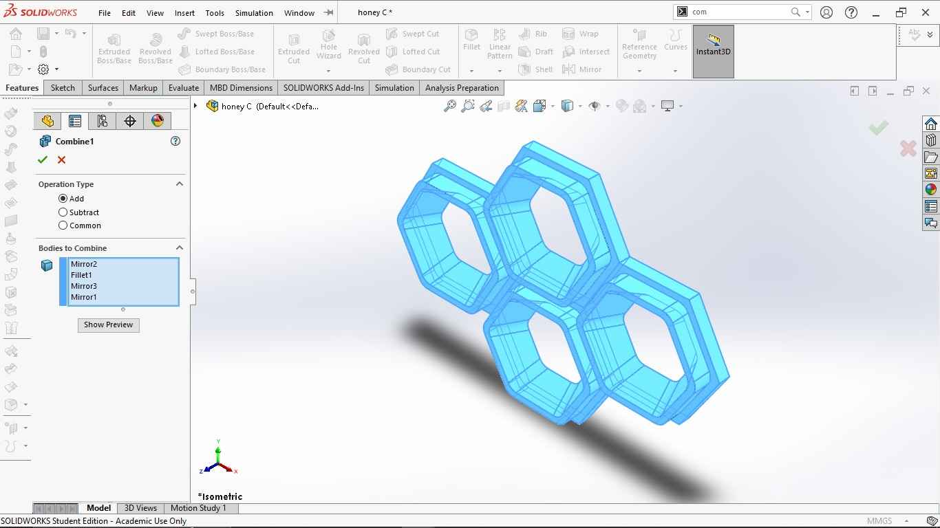
- I need to combine all this 4 bodies. I used search engine to search the combine feature. Drag and select all the bodies and click to the green tick to confirm.
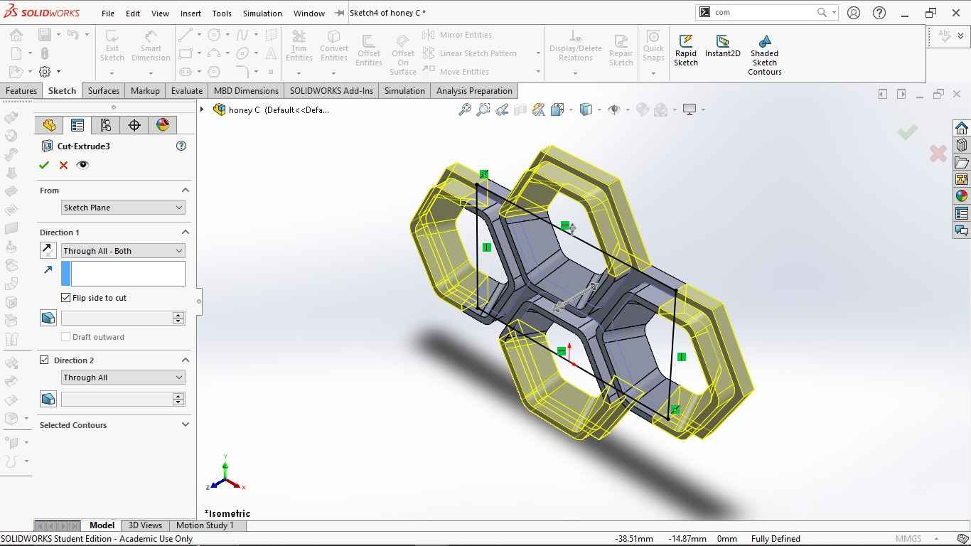
- Now I want to cut the outer portion of the hexagon and I need only the inner side so that it will be easier for me to create circular pattern using flex. I selected the corner rectangle and did extrude cut the outer portion.
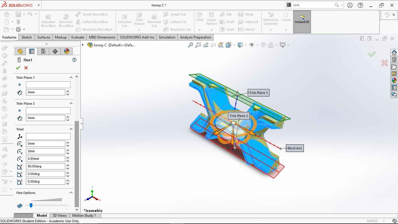
- I used the Flex (flex1) feature to set the trim plane for bending the body into round circular hollow body. I set the angle as per requirement as shown in image.
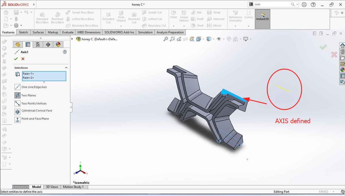
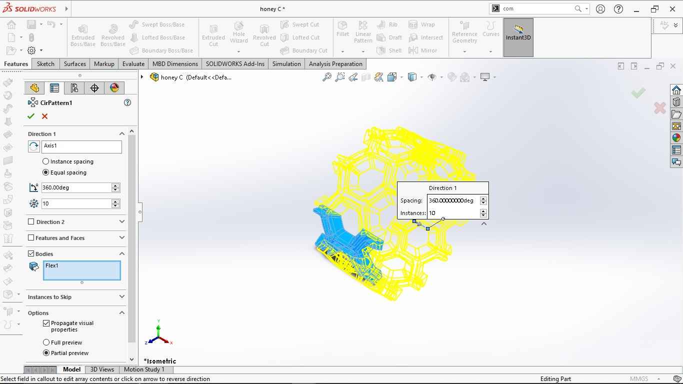
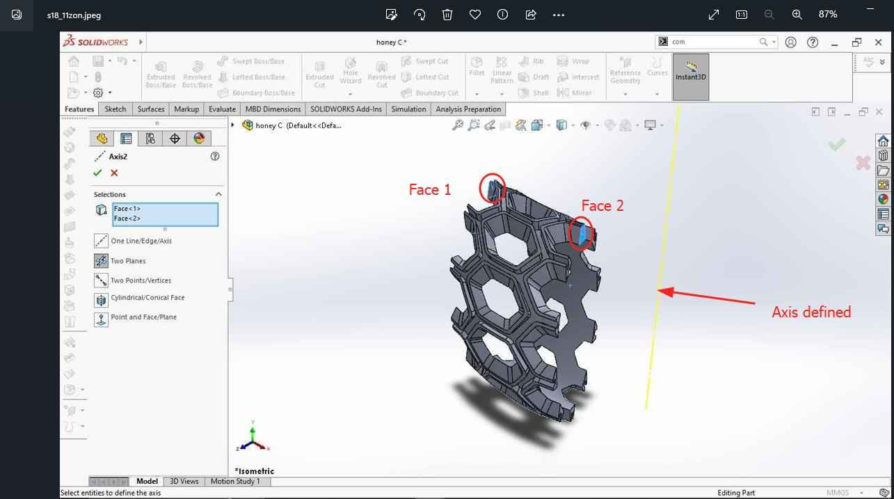
- As I wanted to create a round bracelet I need to give a circular pattern. To give a circular pattern it is important to define the axis. So I defined the bend axis as shown in yellow colour in image. Then I gave the circular pattern and gave 10 numbers of bodies at 360 degree wit equal spacing. Then I combined the bodies using combine tool as done before.
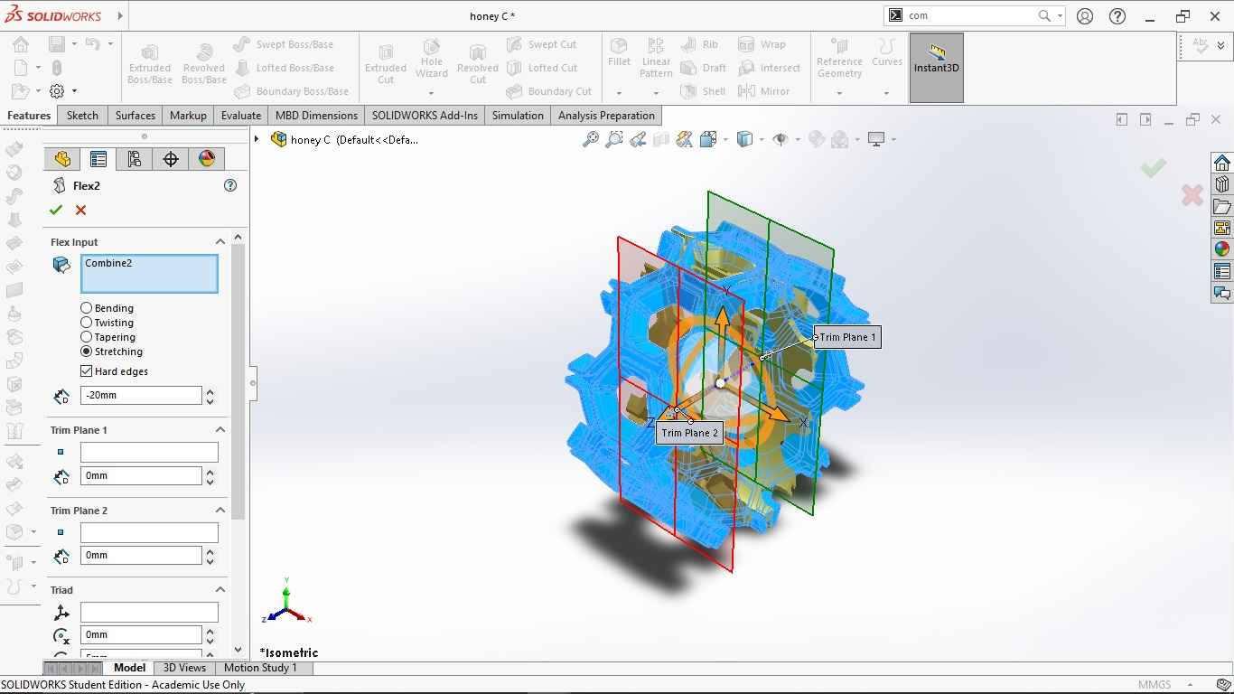
- Using the flex feature (flex2) again I want to stretch the body making it little flat and not a perfect round shaped. I kept the rotation angle to 0 degree.
-
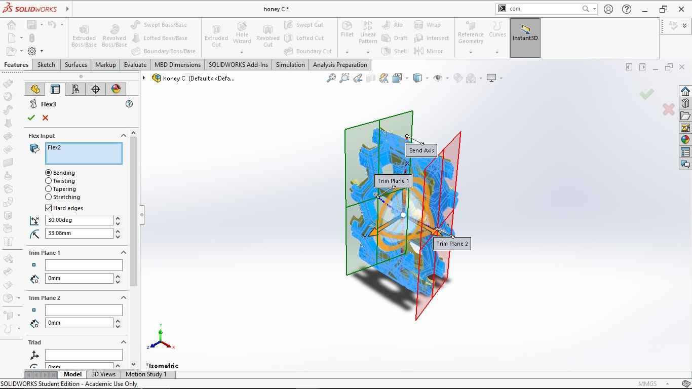
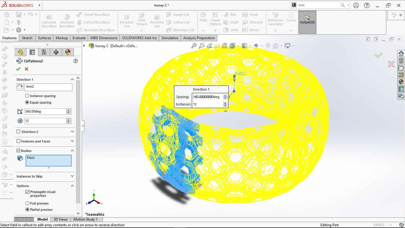
To fit the bracelet on hand i need to make it in circular shape. For this I want to bend around to 360 angle. Therefore, I again used flex (flex3) feature to define angles of rotations. Then I again defined the axis to create a pattern using two faces. I gave a circular pattern of 12 numbers and combined the bodies.
-
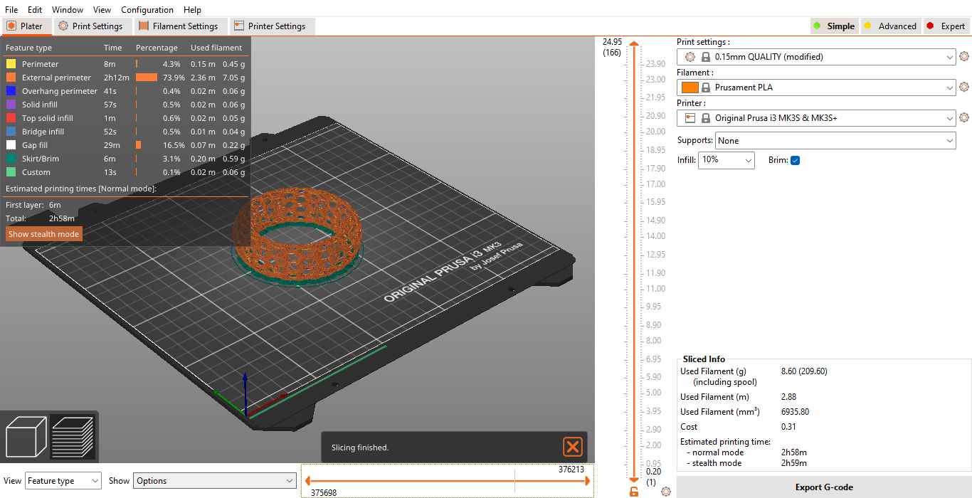
Then I exported the design file as STL and and prepared for printing. I used brim to support the body and used layer height ot 0.25mm.
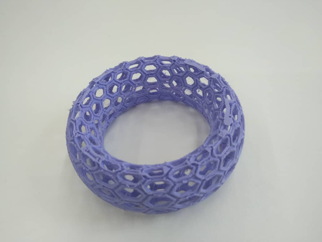
- Here is the final print.
3D Scanning
We have Artec Eva 3D scanner in our lab but unfortunately we couldn’t use it due to some issues in software installation in other computers as the old computer got short circuit.Therefore, for 3D scan I used Kiri Engine installed in phone as suggested by our instructor. I found comfortable to use it. It gives us the option to click pictures for scanning or to record video. I initially clicked pictures but it didn’t work for me. The parts couldn’t assemble properly. So I tried with video scan and it worked well.
Work flow
- Install the softwares from the link Kiri Engine
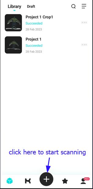
- Sign in with email account and start scanning. It will be shown as below. click on plus sign and select on take photos to start scanning.
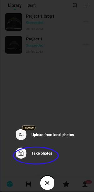
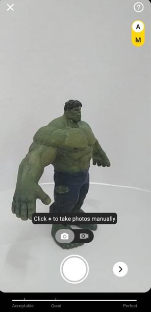
- There is an option for video recording and clicking pictures. We can choose any. We need to take atleast 20 pictures to process the scanning and the picture limit is 70. The video stops automatically when it clicks 70 pictures.
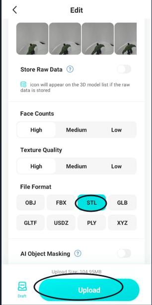
- Click Next to the upload and process. We can rename the file and select the file format. To 3D print the scanned object I selected STL format and the uploaded the file. We can also select the texture quality and I kept it as medium.

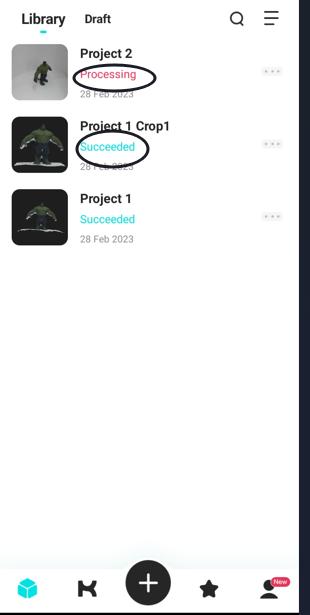
- Once the upload is successful it notifies. Click ok to proceed and it shows in a library list. Processing starts automatically and it takes few minutes for processing which can be seen as Queuing. Once it is done is is narked as Succeeded.
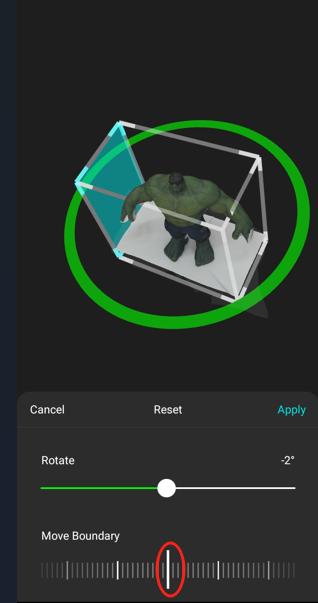
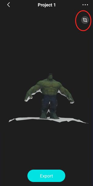
- If we click on the file it prepares for download. Before we proceed for exporting we can crop the unwanted portion like base of the object using crop tool. If we click on export it gives us to enter the email where the stl file will be sent as a zipped file.
 !
!
- The scanned object is ready for 3D print.
!
Design file can be find here