02.Physical design & Fabrication
Physical Design and Fabrication
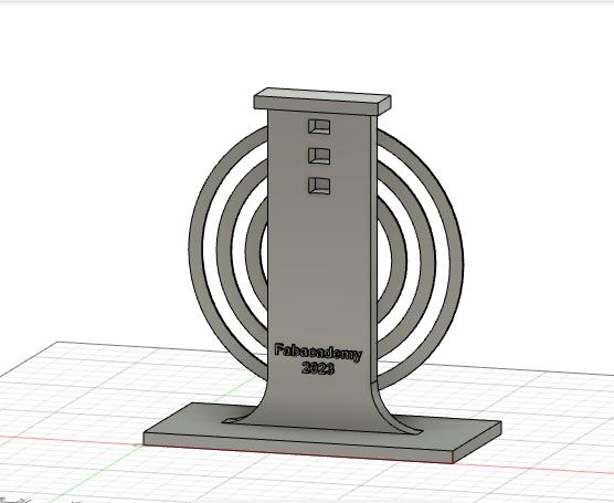
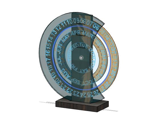
This is a first design that I made in fusion360 during CAD week. I got the ideas from Etsy page for physical design. I realized I need to think more on mechanism part.
Initial rapid prototyping.
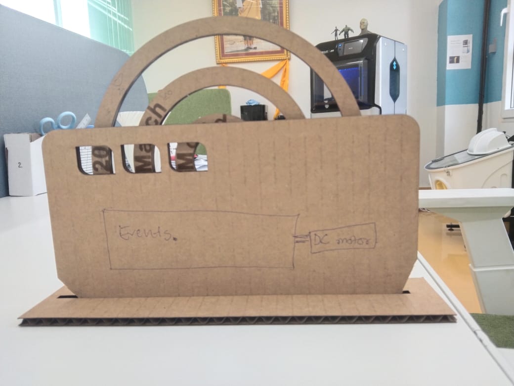
As first prototyping I made only the physical parts with the cardboard and there is slight changes in design. I am changing my design because I am looking for how possibly I can cover the electronics components and wiring.
I used dxf formate file exported from fusion 360. I used laser cutter to cut the cardboard. I cut the three rings for Day, Date and Month. I assembled it with a glue. This is my assembled first prototype. My base is not exactly as designed as I didn’t cut the actual dxf file but I just randomly drew a rectangle in Inkscape and cut it for now for now.
Importance of weekly rapid prototyping session
- This session allowed me to realize where to modify my ideas
- It also allowed me to think and decide on how big my model can be.
- I can decide where to place which components.
- Overall it is giving me the basic initial look of how my project model will be and it allows me to work on the parts which is bit challenging like for me I need to start working on gear ratio and rotation parts.
In the output device week I switch over to use servo motor because if I use DC motor it is quite challenging the get the required angle with few set of gears. In this week I played with DC motor to by giving the minimum voltage to get minimum speed but but the least voltage gives less speed and it will reduce the torque. So I will switch over servo motor.
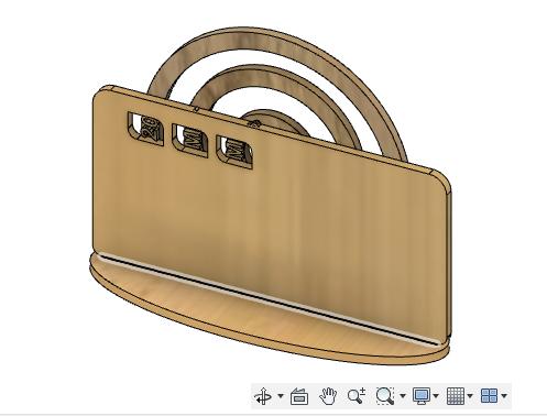
Pardon me for changing my design timely. I had to modify my design as I need to cover the electronics components and also hold the rotating part without providing obstacles during movement. I remodified my design from the previous design and I increased the size of the frame.
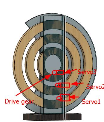
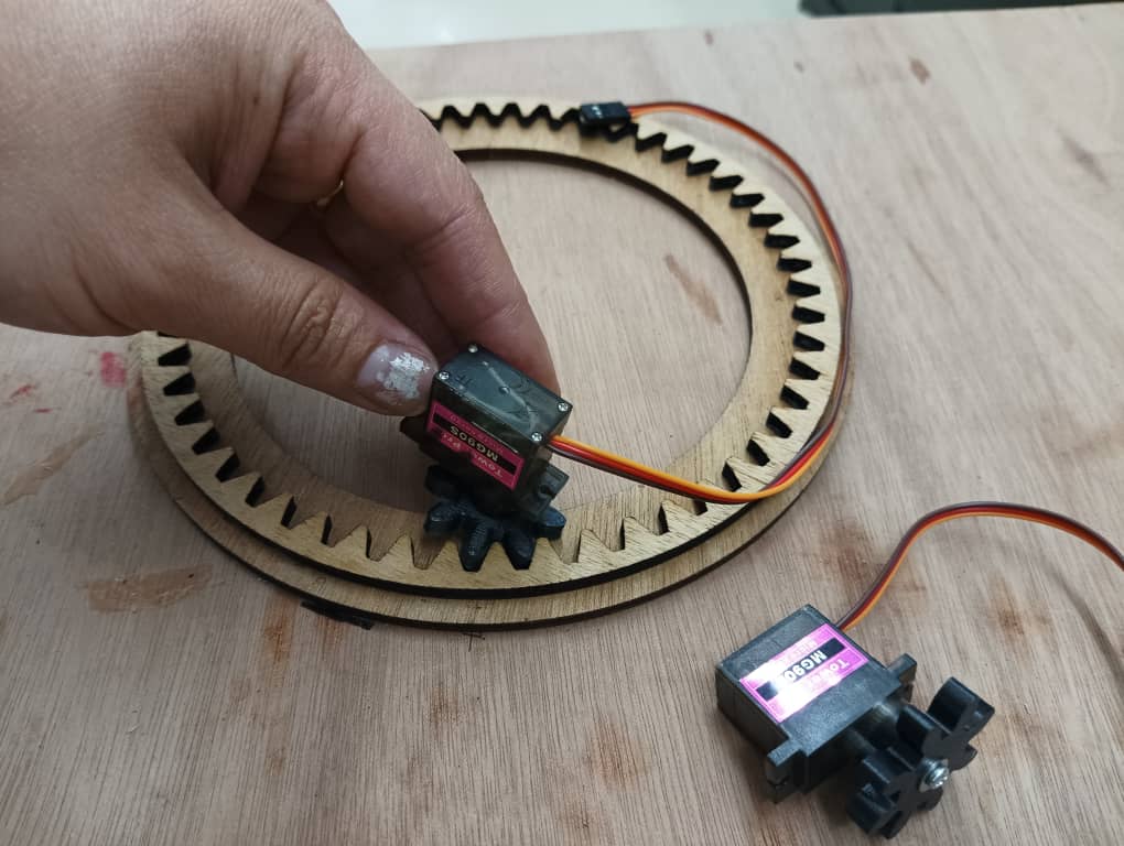
I want to use spur gear to drive the rotating part with servo. So this is the rough sketch of how to assemble it.
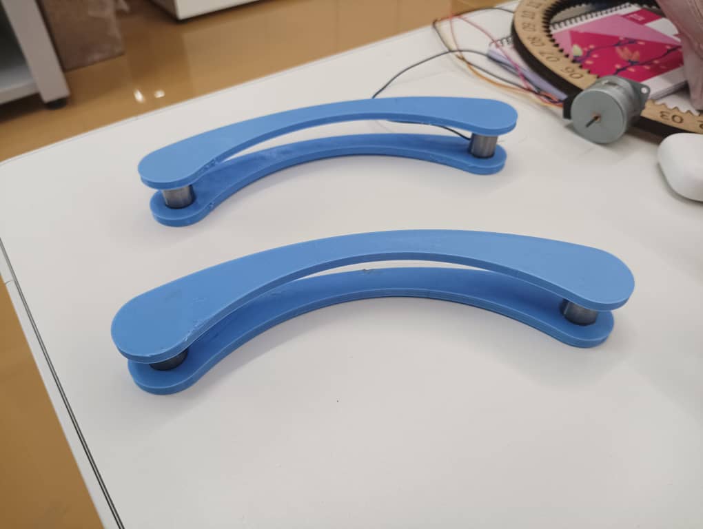
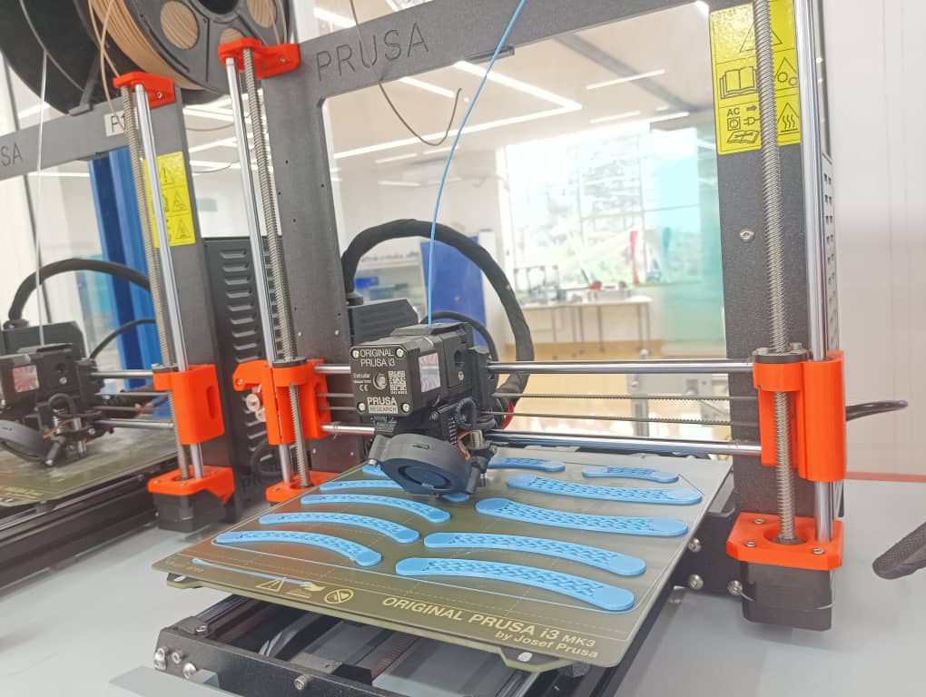
I also designed a bracket to support the rings and did a 3D print. I will use a smooth metal roller to hold the rings hold the rings from both side upper and lower part.
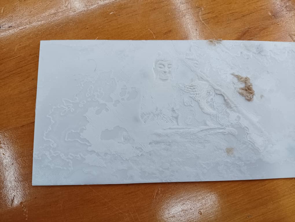
For the front cover I made a options to 3D print and laser engrave. So i did 3D print the Buddha statue on white filament.
For the Buddha printing I use online software called lithophane to convert the image into STL.
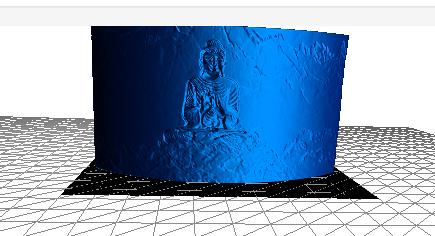
This isn’t looking that nice due to debriss in filament.
I want to do laser engrave the front cover on acrylic and I want to cut the stand and support in shop board but the machine was engaged in other works.
Designing a gear
To design a gear I referred this tutorial.
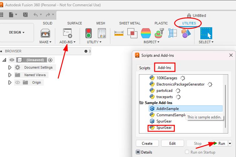
Fusion 360 has a pre-installed add-ins for spur gear. To use spur gear add-inn ->> Utility >> ADD-INNS >> Scripts and Add-Inns >> Add-Inns >> Spur gear >> Run. The message pop up saying gear add-in is added in the create drop down list ->> click OK.
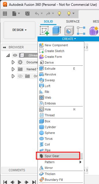
I went back to Solid tab and under drop down list there is Spur gear option.
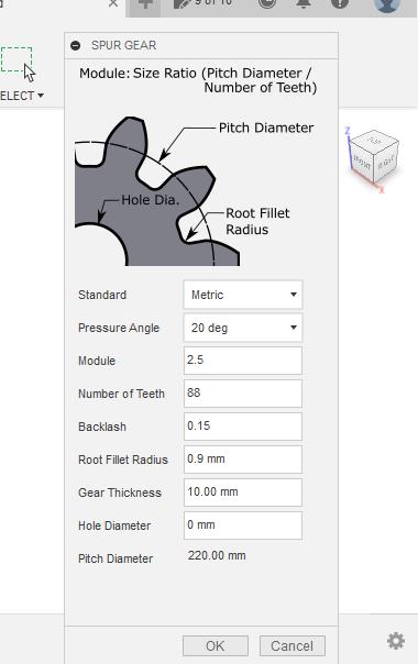
Some important terminology
- Pressure angle: The pressure angle is the angle at which the force is applied between the teeth of gears.
- Module: Ratio of gear’s pitch diameter / number of teeth.
- Back lash: Clearance between two mating gears.
- Root fillet radius: Radius where the gear teeth meet to root or the base of the gear. Always keep less than 1mm.
- Pitch diameter: Diameter of the gear used for spacing the gears
Module and the number of teeth determines the pitch diameter.
I used the settingas below and clicked ok.
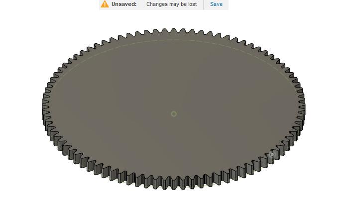
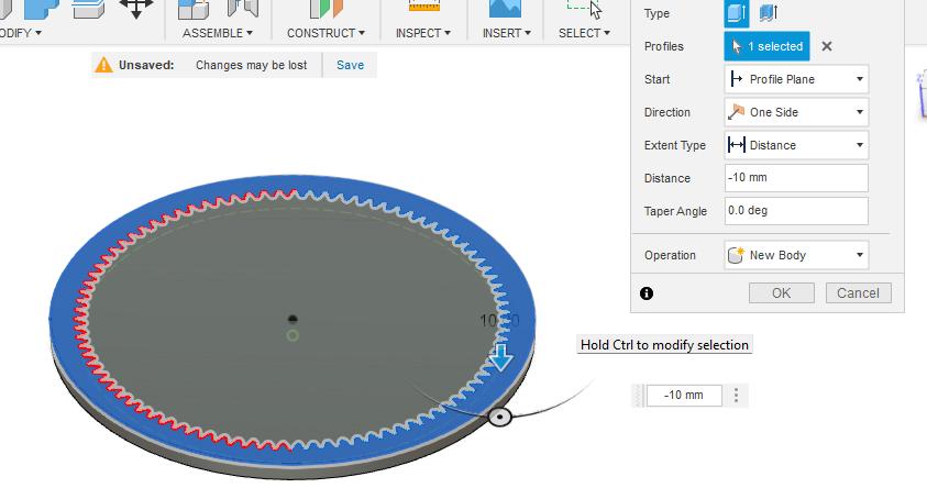
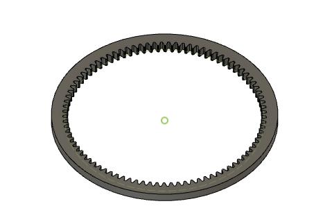
I want a ring gear so I will create a sketch on the top and the extrude the body as a New body. To get only outer ring I will extrude cut the inner part of the gear.
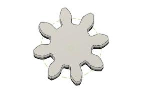
This is drive gear which will be attached to servo.
I projected the body and saved the dxf file. Since the dxf file I exported directly from fusion 360 is getting distorted in Inkscape I used online file converter to convert dxf to SVG which works perfectly.
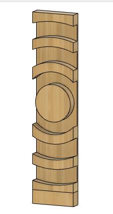
I designed a stand to hold the rings by creating a slot.
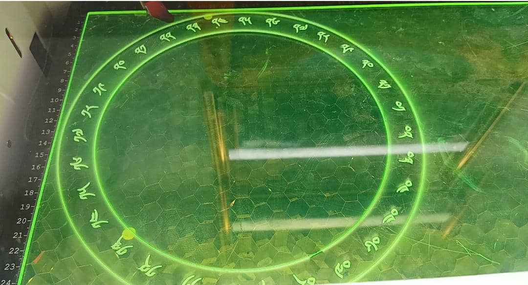
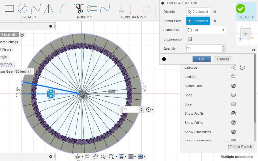
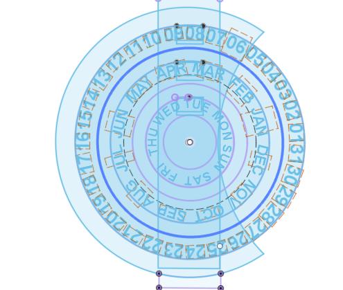
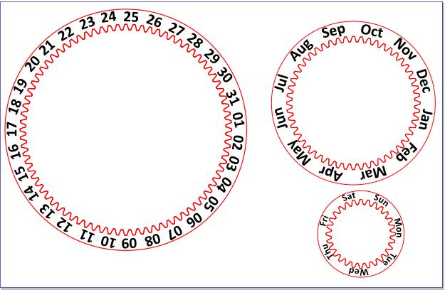
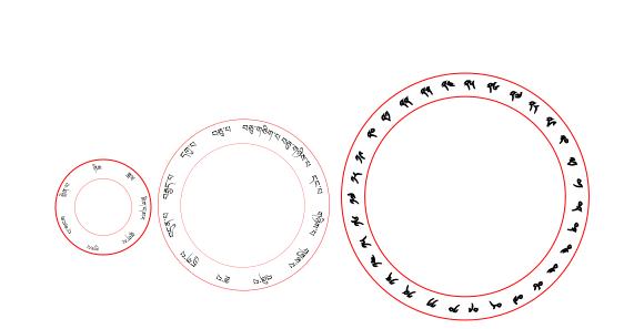
Before writing the text this is how I divided the 360 degree circle into different sections of month, day and date. - For month I divided 360/number of months(31)= 11.6 degree. I drew only I section and rest of the section I created using pattern.
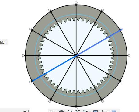
- For date I divided 360/number of days in each month(12)=30 degree.
The text I designed a in Fusion360 did not work even though I converted to SVG. So I directly inported the dxf in Inkscape and wrote text in inkscape and it worked.
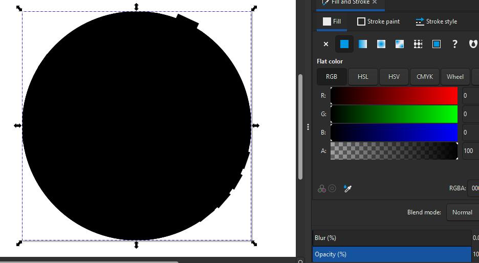
When I gave a fill t to text as I want to engrave it I apeared lik this.
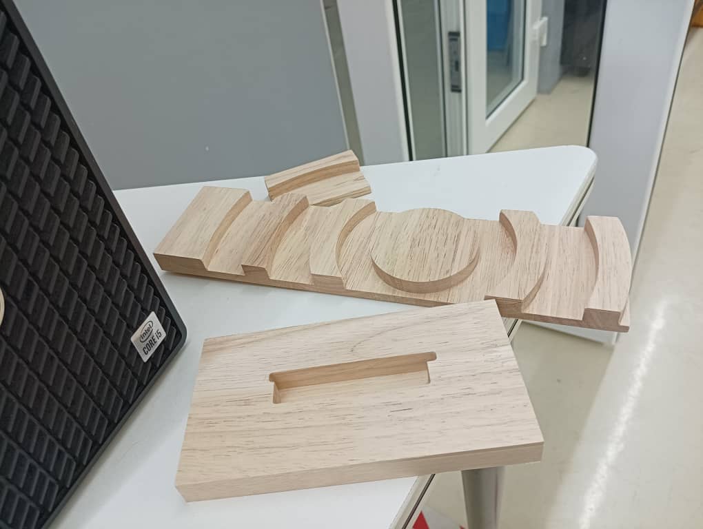
I cut the stand and the base I cut it in shopbot using the hardwood and did sanding. This fitting was not that as I did not give proper clearance.
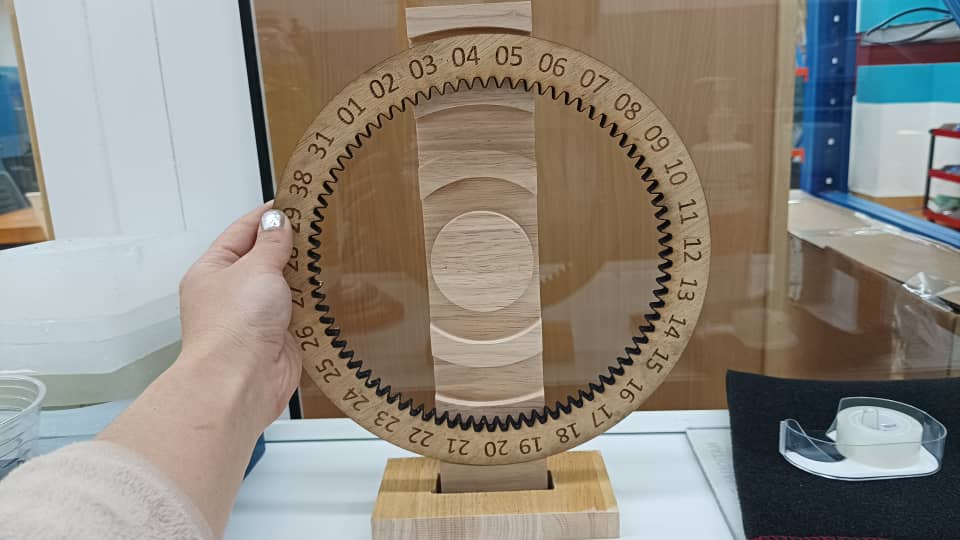
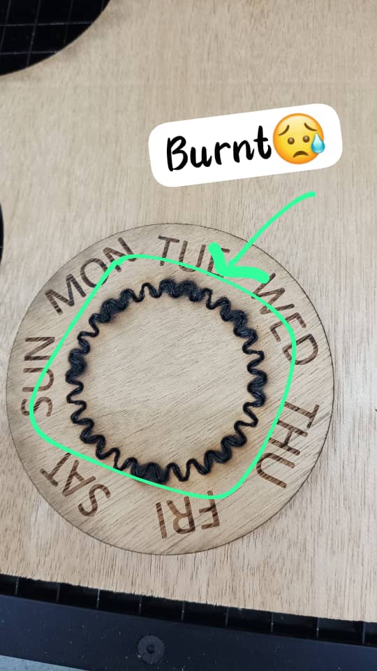
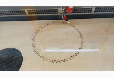
For the rotating part and the front cover I did a laser cut. The gears teeth is getting burnt so I had to keep on playing with power and velocity.
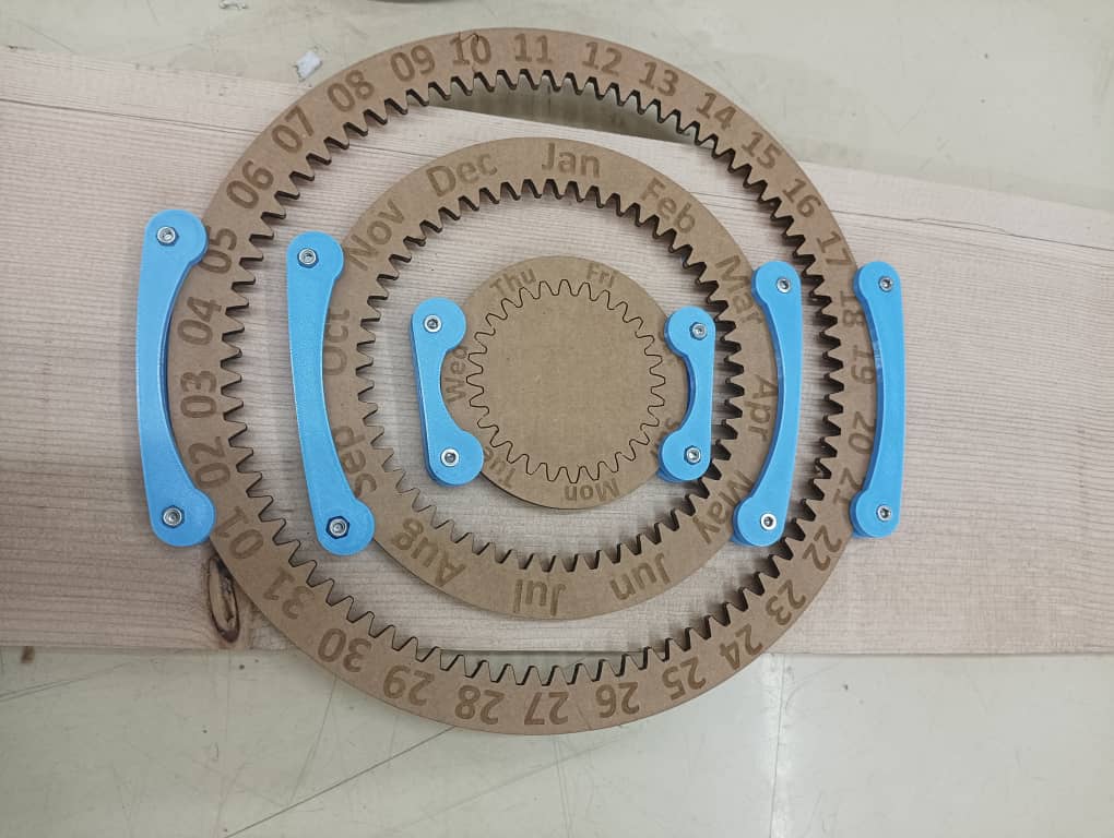
This is my first assembled prototype.
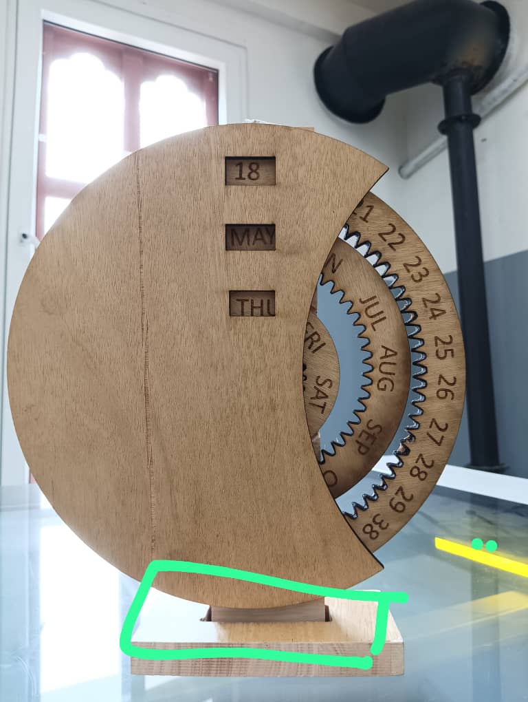
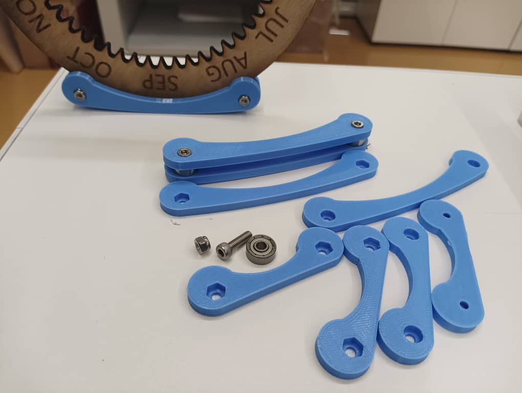
Since the bracket I designed was too think and the roller part was giving obstruction I redesigned it into smaller size with. I modified the roller part to use the bearing.which will let the ring rotate smoothly.
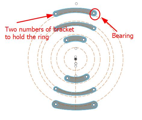
I used M4 nut and bolt to hold the bearings.
The back support that I cut gets easily broken so I decided to use fastner to attached the brackets and the rings
Working on ring sizing the rings
To get a perfect fitting I changed the size of the rings. I studied the gear teeth height and the width for the text using Inkscape. I noticed that the gears I exported from fusion360 gets reduced in it’s size. So when I scale up the teeth height gets changed according to that I adjusted the outer diameter and inner diameter of the rings.
This time I learnt how to make text curve. ->>Draw a circle >> write a text >> select both circle and text >> go to text >> click Put on Path.
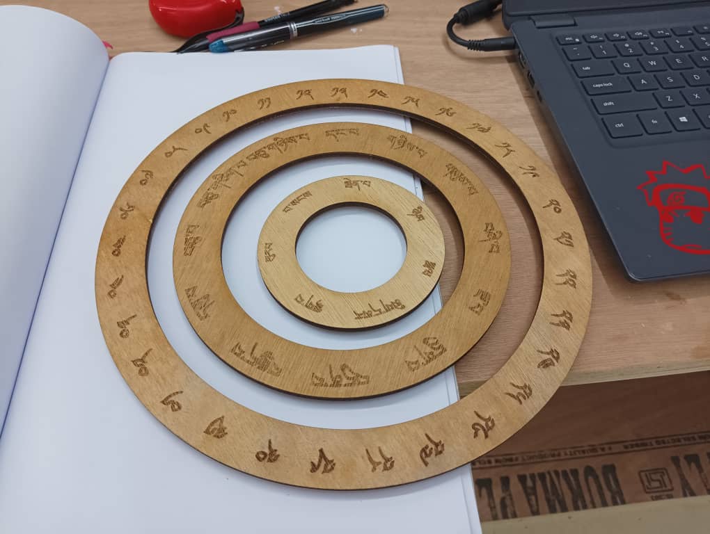
I Before cutting the plywood I engraved the text and cut the rings on cardboard to see sizing as I cannot exactly eyeball the sizes.
To cut the drive gear it was challenging for me. The inner part could not cut properly. So I cutting three times with low power and high velocity. I kept the settings as below.
    Power= 80
    Velocity=1
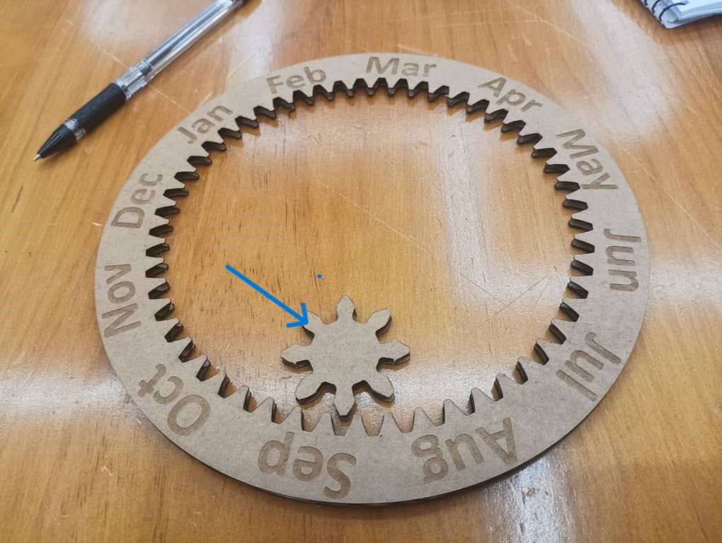
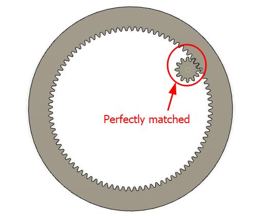
The spur gear teeth got different teeth size as I separately. Spur gear has thick teeth. I redesigned the spur gear together with the ring gear in fusion360. Thanks to Zina for making corrections here.
Redesigning the text
This week Rico gave us the assignment to make a story board so I brainstormed alot for the story boarding and along with this I decided to change the text into local language and the reason is here.
I engraved the text on laser cutter and it looks quite blur. Ofcourse I will be using the different ply wood where the engraved text can little brighter.
I cut the driven gears on laser cut and pasted on the back side of the ring. I did 3D printed the drive gears and attached to the servos.
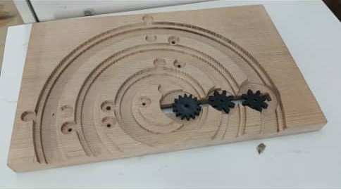
For the back stand I firstly cut the particle board but I found it has rough surfaces at the milled potion due to particles. So I switched on hardwood and milled in CNC router. For the first trial It was smaller and ring was not stable.
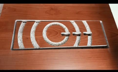
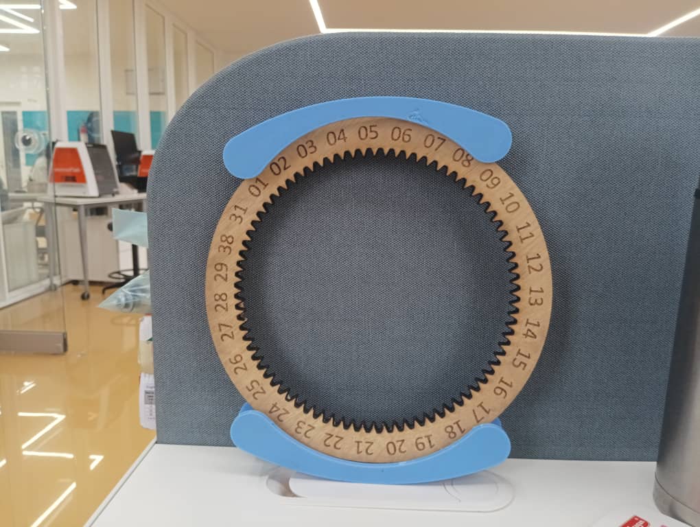
Now I decided to use the hardwood as a back stand and I cut it in CNC Router. Now my rings fits well as I assembled s below. I used the bearings as a roller and mounted the servo motors from the back. I did a sanding with a sand paper for the smoothness around the rings and the slot as well.
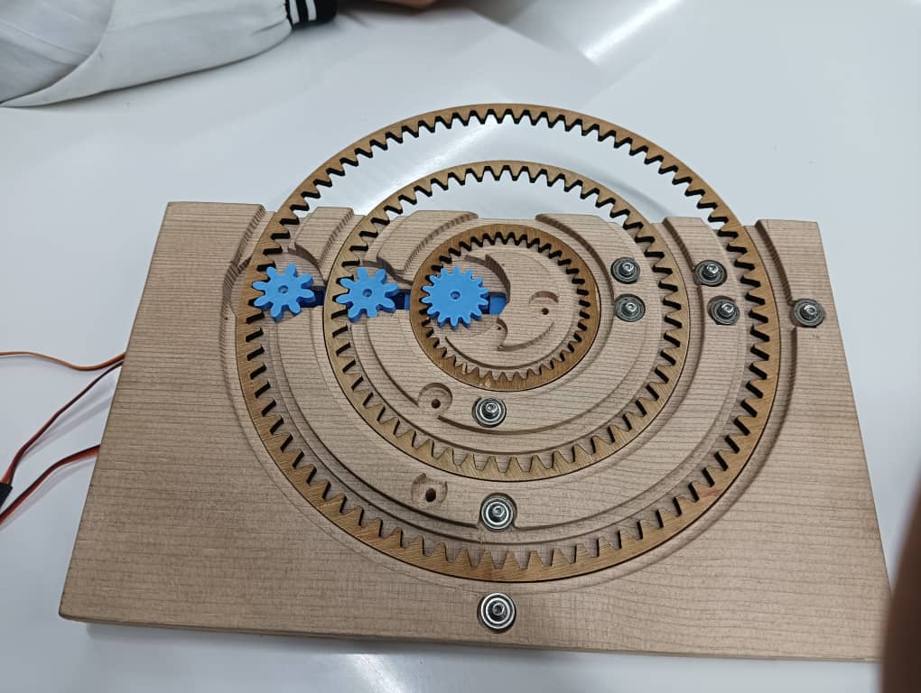
After assembling the parts I did a mechanical test and it is linked here.
For the rings I decided to engrave on transparent acrylic as suggested by the visitors that it looks good when the gears are visible. I will attach the gears behind the rings.