Week 02. Computer Aided Design
In this week a bunch of 2D and 3D designing softwares are introduced and mostly are new for me. However, I want pick the one I am comfortable with and already familiar with. The following softwares are already installed in my computer and I frequently used Fusion360 for 3D design and modeling and rest I used it seldom.
Download links for the softwares are shared below:
Goal of this week
- Able to differentiate Raster Image and Vector image.
- Trying with different 2D and 3D design softwares.
- Learn rendering, animation and simulation in CAD softwares.
- Try compressing video using FFMPEG and image compression using different softwares.
Assignment of the week
- model (raster, vector, 2D, 3D, render, animate, simulate, …) a possible final project,
- compress your images and videos,
- and post a description with your design files on your class page
2D design
2D design is in two dimensions typically in the form of images like drawings, paintings, prints or photographs. 2D can be looked into two different ways- Pixel-based Graphic Design known as Raster image and Vector-based Graphic Design known as vector image.
Raster image vs Vector image
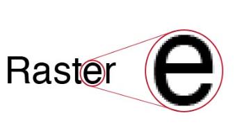
Raster Image
- The images formed by combination of numbers of coloured square box called pixel or tiny dots.
- When image is zoomed in the pixel becomes more visible turning image blur. The resolution of image is determined by the number of pixels.
- If image has more pixels it will have higher resolution.
- Some of the raster file format are JPEG, GIF, or PNG. GIMP is software where we can design raster image.
Vector Image
- Vector images are consist of points and lines to create paths.
- also known as scalable vector graphics (SVG).
- Image does not depend on pixel.
- Images can be scaled infinitely without losing quality.
- Vector files are best format for generating tool path for cutting in machines like laser cutter, vinyl cutter, and CNC router.

Inkscape
- Vector graphics editing tool
- It is free open-source tool.
Inkscape workflow
-
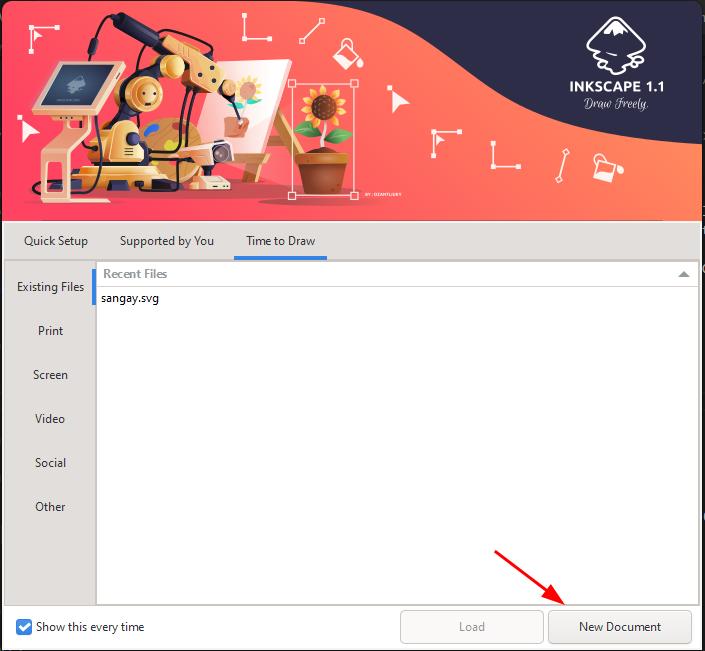
As you open the software you will find this page shown belwo and click on the “New Document”.
-
You can either create a new file or import the images by following this step: File >> New or Import.
-
To zoon in and zoom out press ctrl+Scroll up or down.
- To move the image hold on left most button and move the image.
- If I zoom in the image I can see pixels as the image is raster image. In order generate tool path to cut machine I need to make it into vector image.
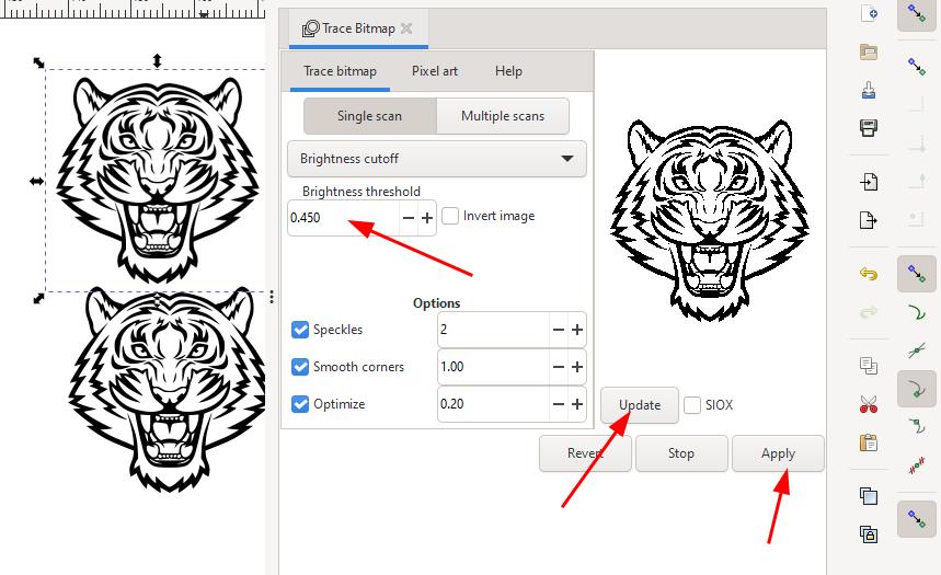
- To make into Vector image: Select the image >> Path >> Trace bithmap >> Update >> Apply.
- We can delete the raster image and keep new one and export for cutting.
- In bithmap tracing we can adjust the Brightness threshold as per the image-In some images.The threshold can be set from 0.0 (black) to 1.0 (white).
- The higher the threshold, the fewer the number of pixels which appear as white.
Gimp
I haven’t used Gimp before but I learned that this is a free open source image editing tool. It can be also used to change file size. GIMP can be a very useful and handy tool for quick image modification.
Getting started with GIMP
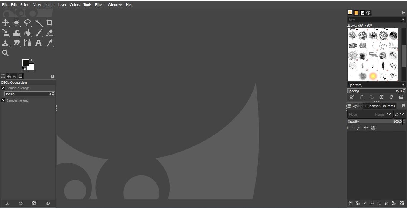
- As you open GIMP you can see empty area in center called canvas. If we want to create a new file we can go to FILE > New or we can open an existing documents by opening recent documents.
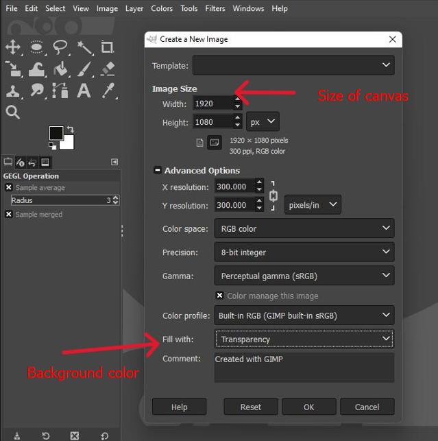
- When we click new file the window pop up. We can adjust the size of canvas-height and width are measured in pixels by default.
-
We can also go to advanced setting and change the setting like background colors if we are adding stuffs.
-
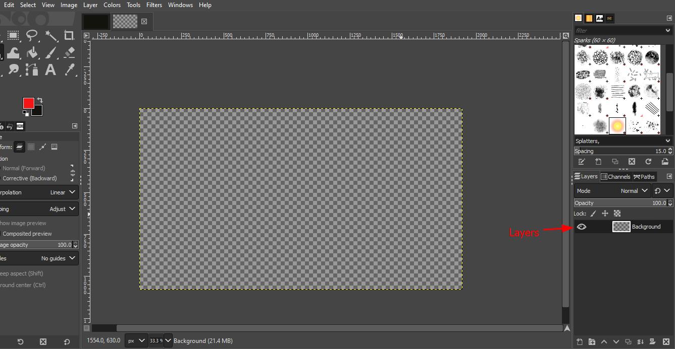
Transparent background is indicated by the chequered boxes on canvas.Transparency is relevant Tto export file format like PNG.
-
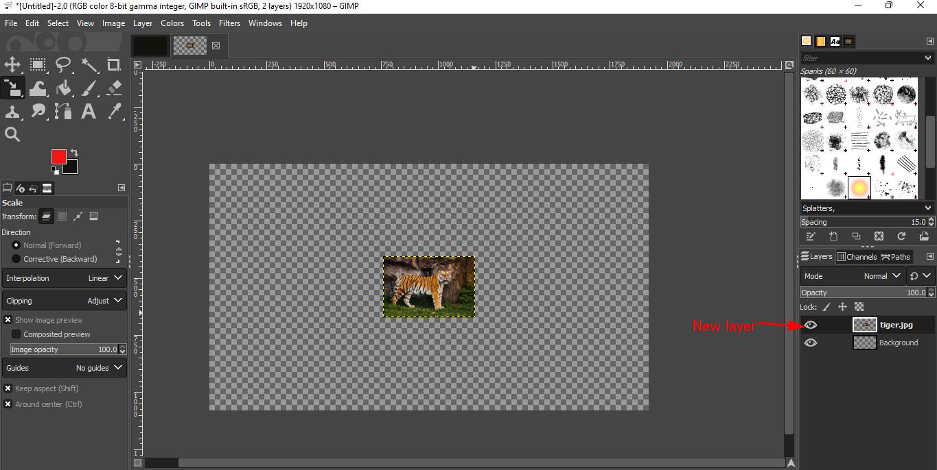
To import the file got to > File > Open as a layer >Select the image and click open.
-
As the image gets opened you can see the layers at the bottom that the image itself have its separate layer. Any changes made in one layer are separate from changes made to other layer.
Some of the tools most oftenly used:
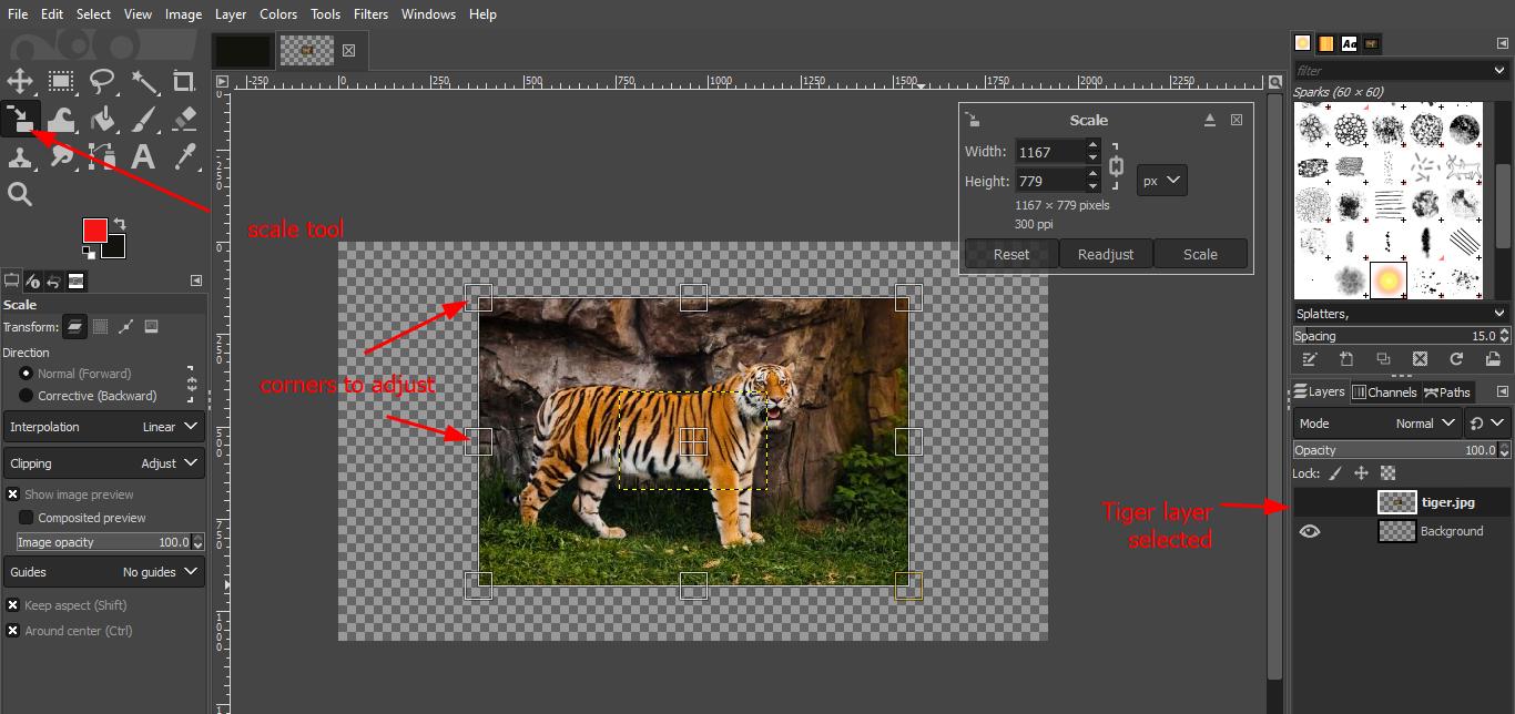
- Scale tool: Select the tool as shown below > Select the image and stretch out or resize from the corners. Make sure that the current layer is selected.
-
If you want to scale down the center point check in the box.This could be convenient for scaling up the images because we don’t hv to adjust everything later on.
-
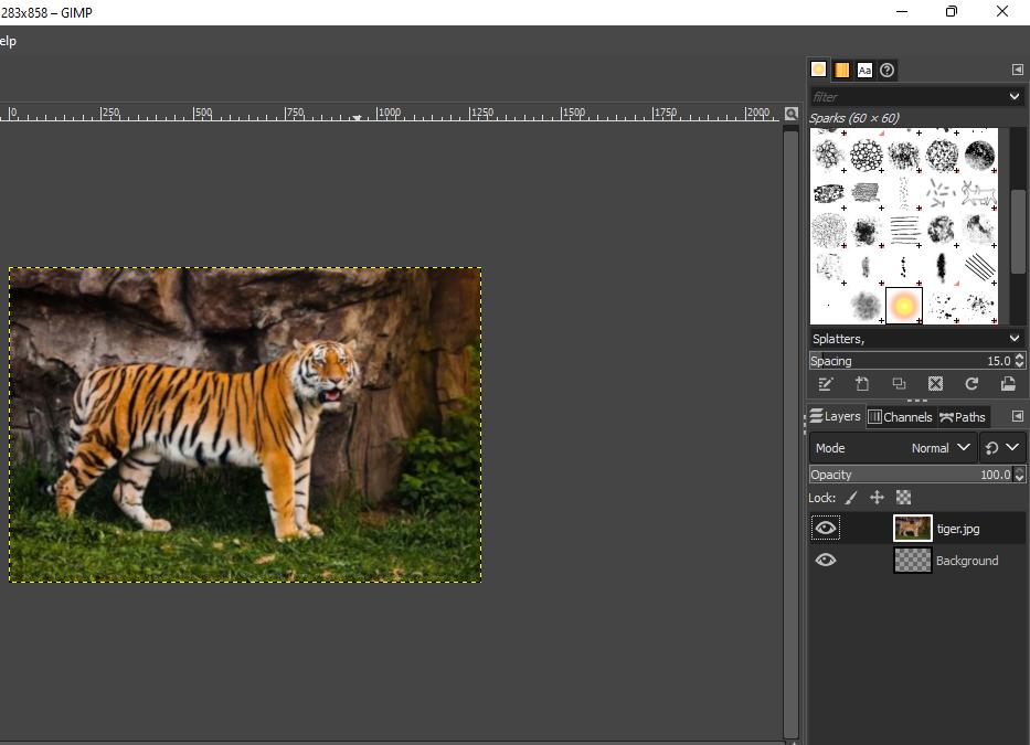
Crop to Content: Image menu>crop to content.It is important to know that canvas frame is what we are going to export it. So to removed the unwanted blank area(It cuts away the area where there is no information depending on our selected layer).
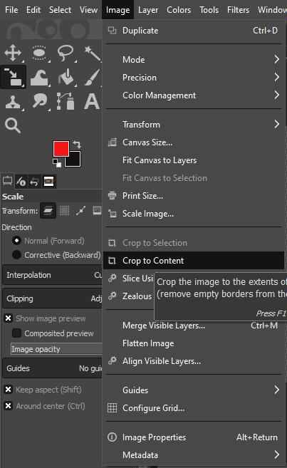
- This is the image after crop content operation.
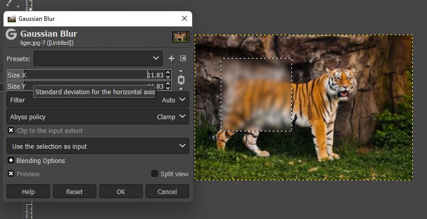
- Rectangle select tool & Ellipse select tool: Are the pretty handy tool when we need to grape one region of the screen.To select specific control we can use Free select tool.We can go to filters menu and for instances if I select blur,this rectangular area gets blurred. In the filters menu there is many different effect we can apply to images or specific layers of the images.
-
Some of simple and useful controls are:Hold a middle mouse and drag around it will pan around the images and can look around the images.Zoom in and out:ctrl + scroll up and down for zoon in and out.
-
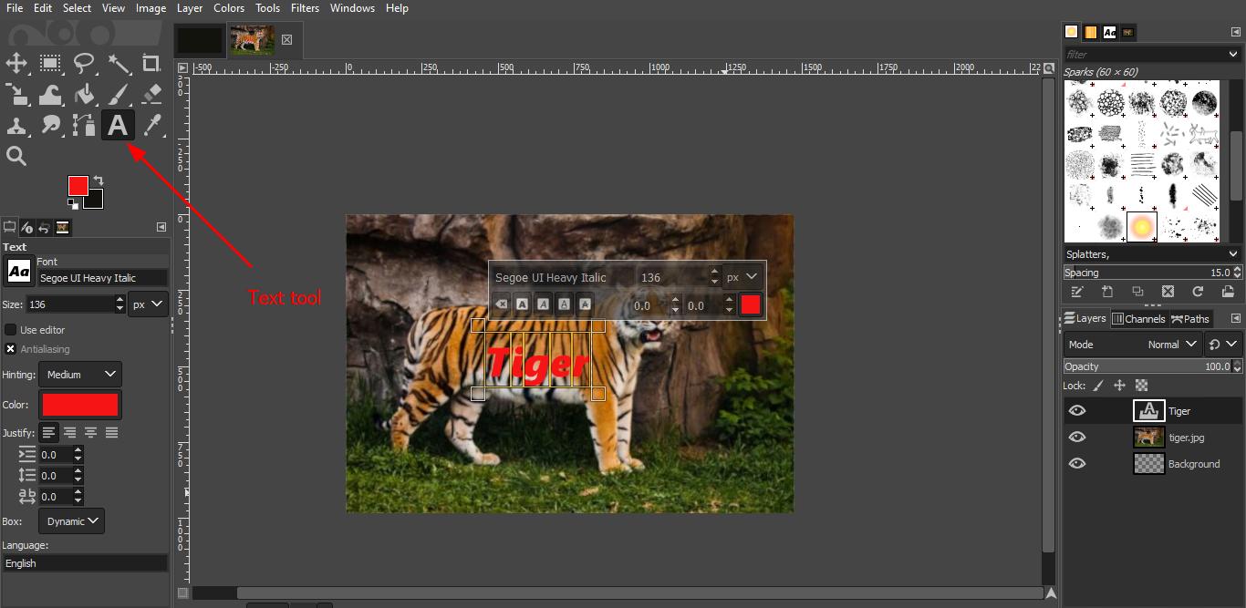
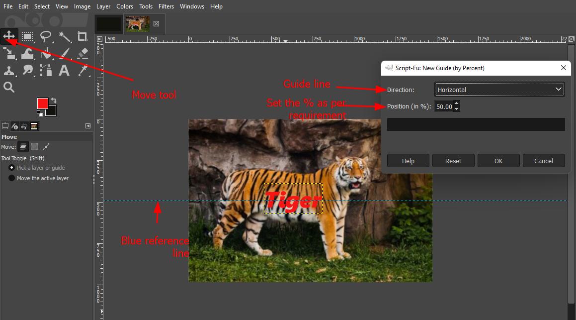
We can also create a text in GIMP: Select the text tool and click on the screen and type the text and it creates a new layer for the text.Use ctrl+ A to split text into individual.
-
Centering text to other objects:Image menu> guide>New guides by percent.Select the one vertical or horizontal. According to that middle blue line will appear.
-
Go to the move tool(M key) > Select the layer selection>left click on the text layer and move it around where ever it need to be and It will snap to the guide.
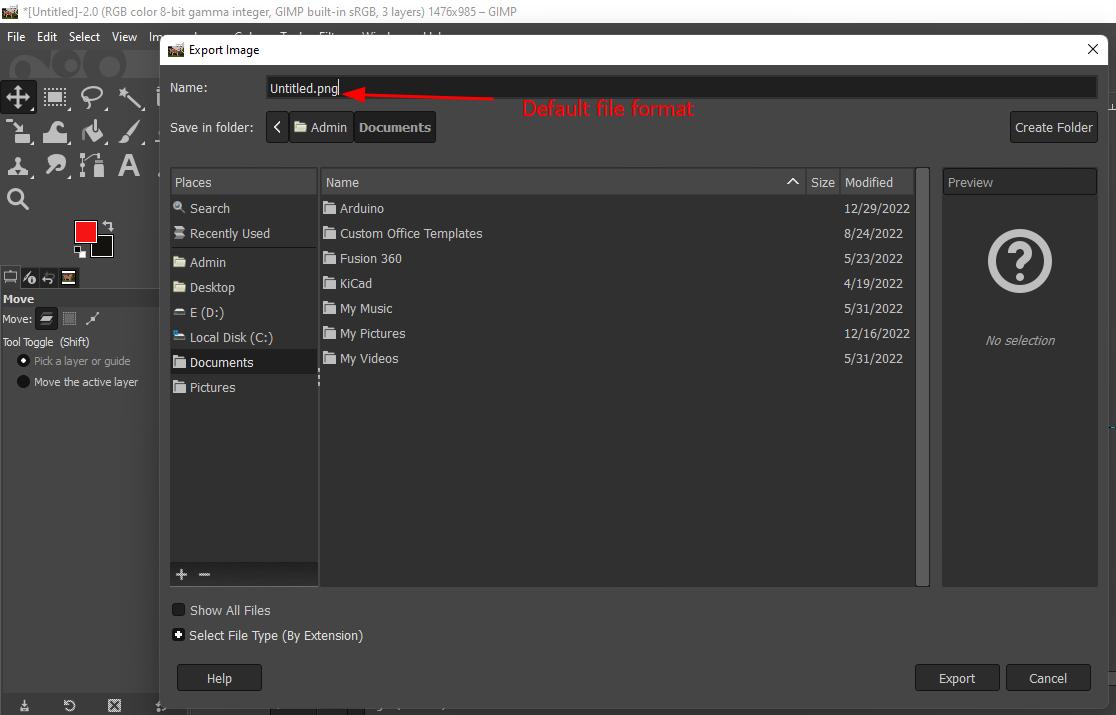
- Exporting file: GIMP uses the Save command only for saving images in its native XCF format.XCF format allows to edit the images later. When you need your image in a different file format, you can use the Export command.With this file browser, you can edit filename extension directly in name box (default is “Untitled.png”) or by selecting a file in name list. You must also fix the image destination in Save in Folder.
Link I referred GIMP tutorial
3D Design and modeling
Fusion360
- As you open fusion 360 software you will see this page. Click on Create sketch. If its not on the menu bar it can be under create drop down list.
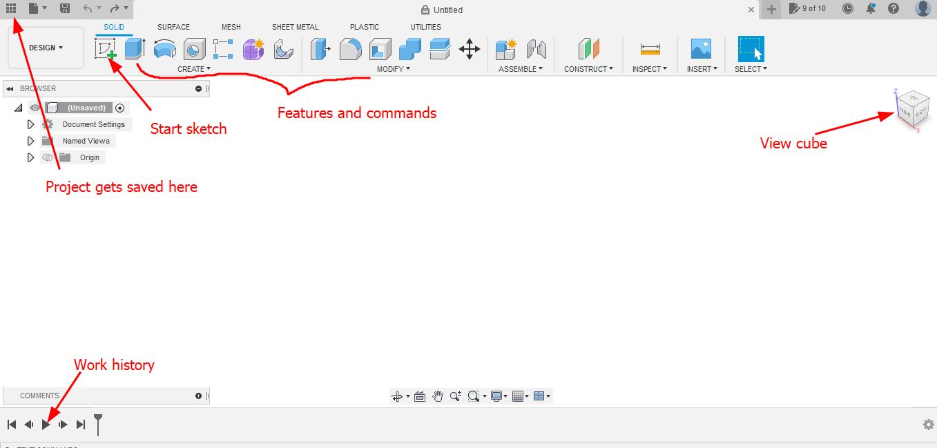
- When we begin to sketch it will be in 2D. Before sketching we have to select the plane on which we are going to perform sketch.
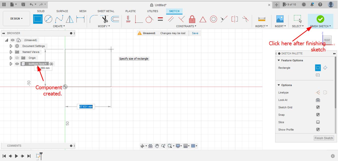
- Firstly created a new component. Go to Assemble Menu > new component > in dialog box check empty component and rename the component (bottom box) click ok.
- Select any tool. I will select rectangle tool and click on center origin and drag out mouse and place it any place.
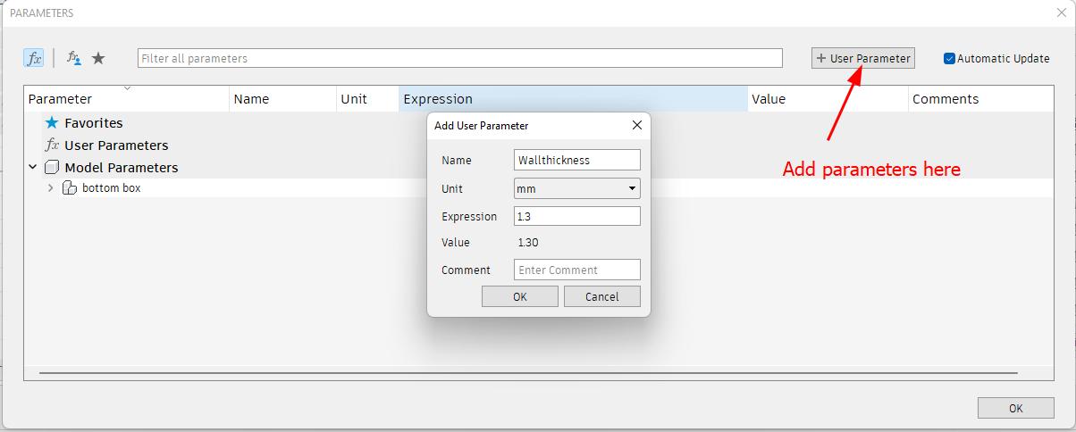
- Sketches should be fully constrained and dimensioned. Therefore I need to set user parameters. Go to modify drop down menu >> select change parameters. Click on the use parameters dialog box and enter name and dimension.
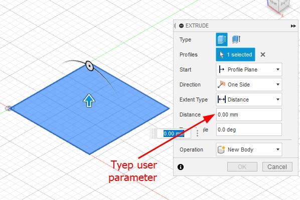
- Use extrude comment(letter E)There will be extrude dialog box, we can type the user parameter to in the distance of extrude.
- I want to use shell feature to make cube hollow.from Modify drop down list select shell too. If we select only one face shell tool it will cut away that face and create the thickness we apply. But we want our cube to be completely closed because we will use split tool later.So to keep the object completely closed we have to select all 6 faces of the cube and type wall thickness set as user parameter in the “inside thickness.”click ok.
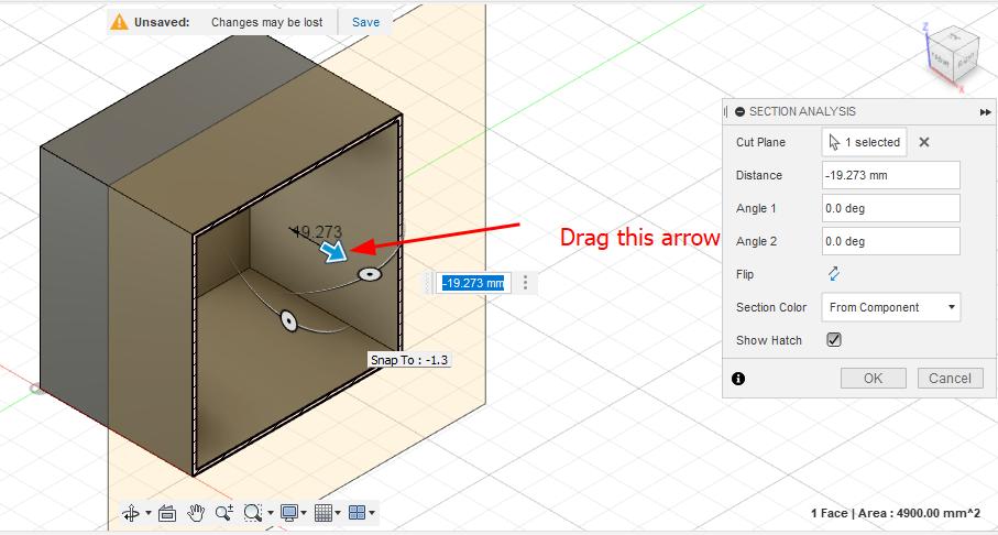
- To check the shell worked properly go to Inspect menu > section analysis. Select any side of the cube and drag the arrow in a bit.There we can see it worked.Click cancel.
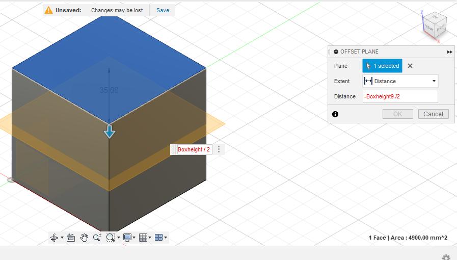
- To split box in half i need to create new plane.Construct menu> offset plane.I will select the top of the cube.For the distance i will use -sign because i want it to go on the direction of my cube, the ni will type box height parameter/2 .This will put construction plane directly in the middle of the box. If we change the height of the box later construction plane will always be in middle because we use half of box height parameter.
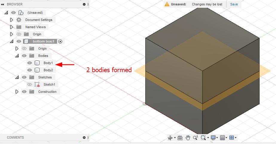
- To split the box in half go to modify menu drop down list > split body. Select the cube body to split and select the constructing plant as a splitting tool.Click ok.
- If we look in body folder in fusion 360 browser we can see two bodies formed.Lets rename this as bottom body and top body.
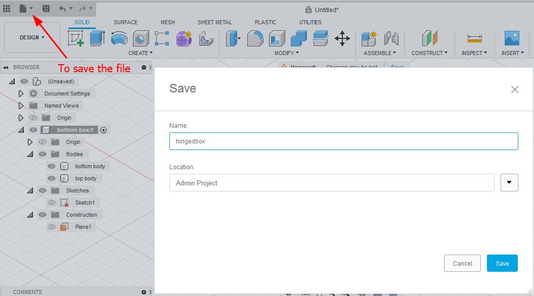
- It is important to save the file. Go to file menu > Save as or ctrl + S.Rename the file and click on Save.
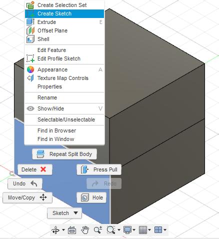
- To create hinge of the box;Right click on the bottom face and click on create sketch. Im going to draw a line from the center of the box over to the right.I will select the circle or hit letter c to create the circle and give the dimensions.I will give the dimension of 45 degree angle.
- Extrude the hinge as a new body so i can hide it later and design new body.Rename it as a bottom hinge.
- Hide the bottom hinge in the browser and reshow the sketch part.Extrude as the top part same.
-
To interlock properly we need to break apart the hinges.hide the everything except bottom box. Right click on top surface of bottom box and create sketch.Create a rectangle of 5.5mm long and width =wall thickness.To work hinges properly by twisting i need to create more rectangle as a gap.Select rectangle tool and give length 5.5 and gap parameter as a width.
-
I want to draw a line by hitting letter L(short cut key for line) and select construction in th dialog box and draw in middle point constraint(can see triangle) and drag out in random distance.I want this hinges to be divided in third.Therefore before I mirror it I have to create one more gap rectangle.So i will draw another construction line down from center line 11.5mm.
-
To mirror I will select the mirror option from create drop down list. select all the rectangle and select the construction line as a mirror line.CAfter mirroring check the lines are black which indicates it is fully constrained.I will extrude all the gap rectangles except the outer two.In extrude dialog box I will change direction to two sides, select all* in the extent of both sides and set operation to cut and set object to cuts and in drop down list make sure bottom hinge and top hinge is checked.Click ok.
-
Multiple bodies are formed after cut operation. I will delete some of this to make hinge work.Select the bodies and right click and click on Remove.
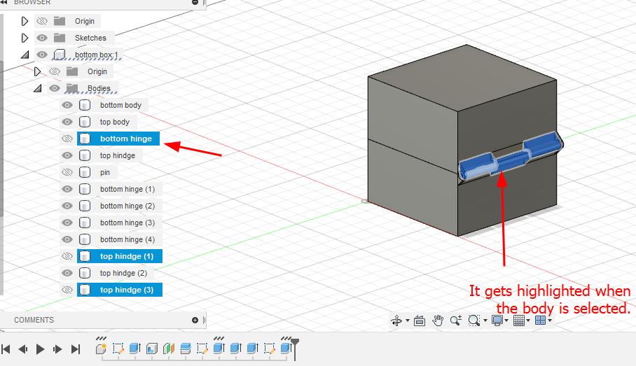
- Remove feature take off all the features from the browser but it keeps them in the timeline down at the bottom and it allows us to see the history. Whereas delete key will get rid of all the traces of the object. Since we deleted the some parts of the hinge it ha now space to revolve around the center pin.
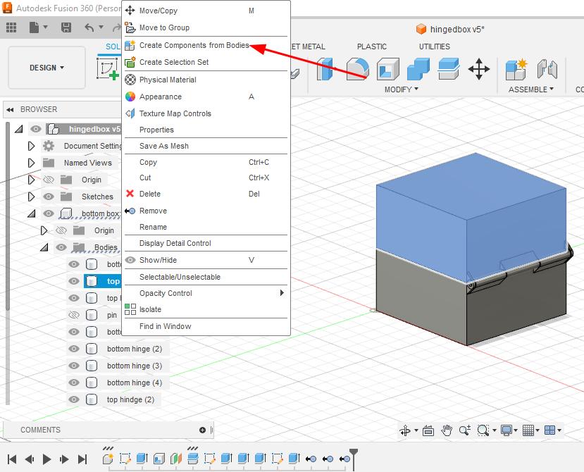
- I will create a component at the top of the box so the box can rotate around when 3D printed. Right click on the top body > create components from body.
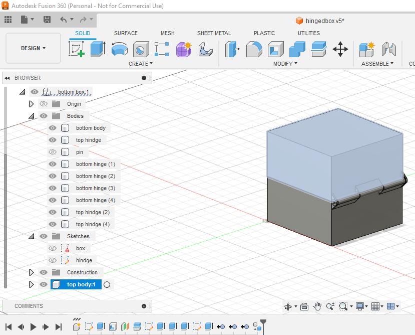
- Now we notice that the new components palace within the bottom components that we started with which we don’t want it. So click on the new component(top body component) and drg it to the top of the browser tree and we can see now it is nested as the same level as the bottom box component.When we go back to the browser tree we can still see some of the top box component are still with bottom component.so we can select all this including pin and drag and place it on the top box component.Toggle On and off each components and see the bodies are correctly nested under the components.
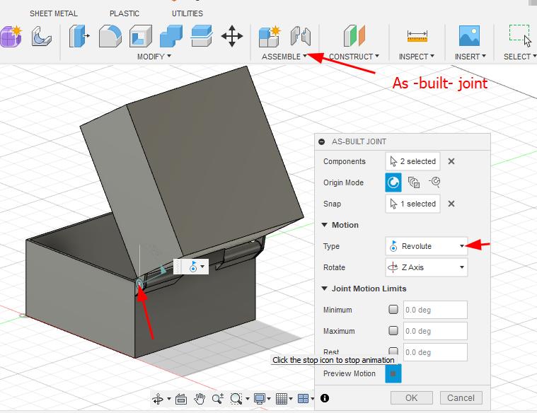
- I will add the joints so that the lid rotate. Go to Assemble menu > As built joint(Allows us to position the component relative to to one another and it let us add motion). Select both the components and we can set the motion to revolute.Zoom in the pin and select the center of the pin.In the dialog box click on play button next to Animate we can see box revolving around.Click ok.Double click oon the revolute around and and open and close the box by dragging the slider around.
FreeCAD
FreeCAD workflow
- Select the work bench and create a new project.
- Click on Create New to create new project.
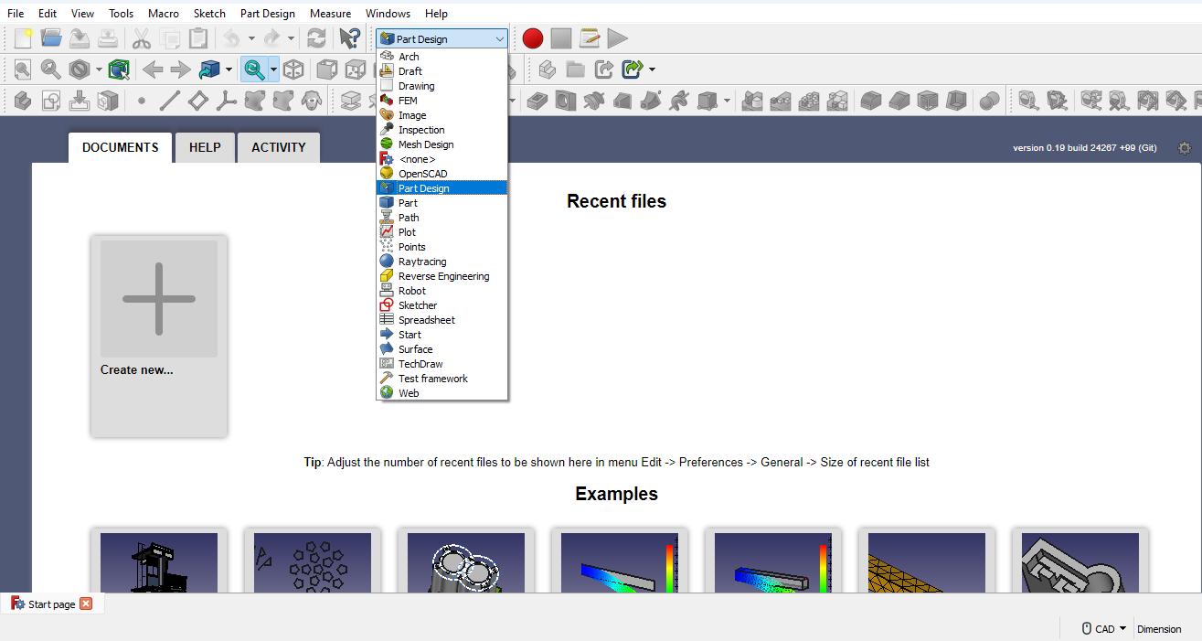
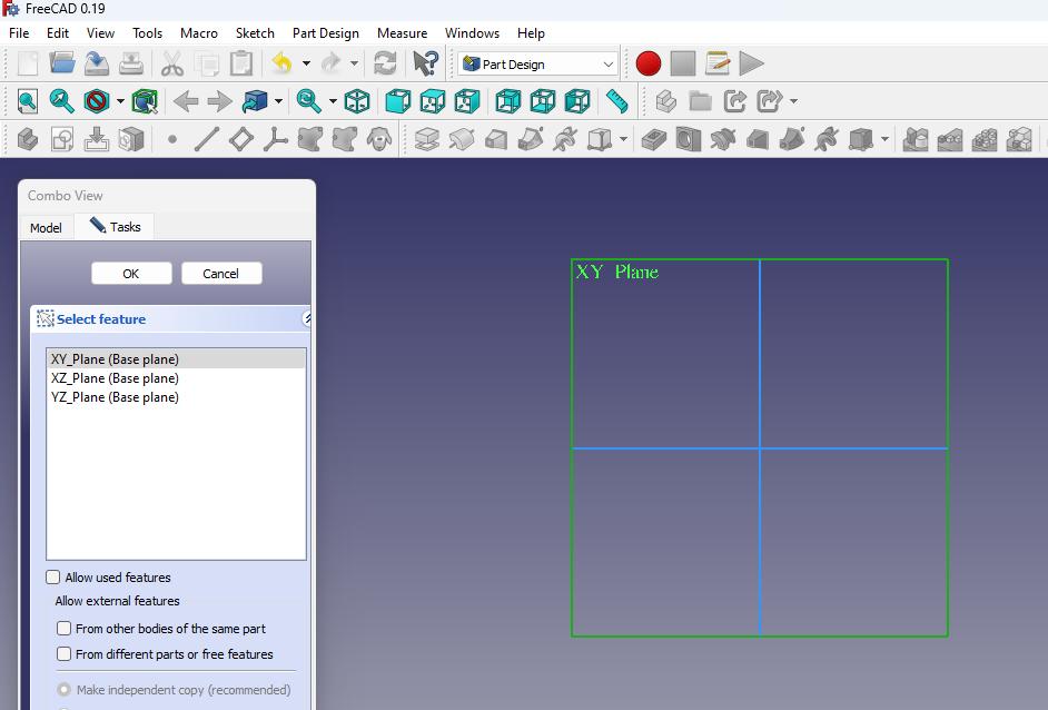
- Start sketch by clicking on and the sketch is created on a plane.there are three planes we can choose from and most commonly used XY plane and press OK.
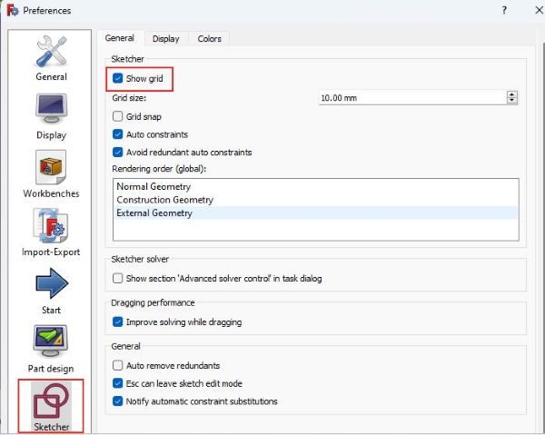
- Grid wasn’t showing on work plan so I went to Edit >> Preference >> Sketcher and Check marked in gride option and click on apply >> OK.
-
To zoom the view use mouse wheel, To rotate the view use right mouse button + shift key and move the mouse, long press middle mouse button allows to pan around work plan.
-
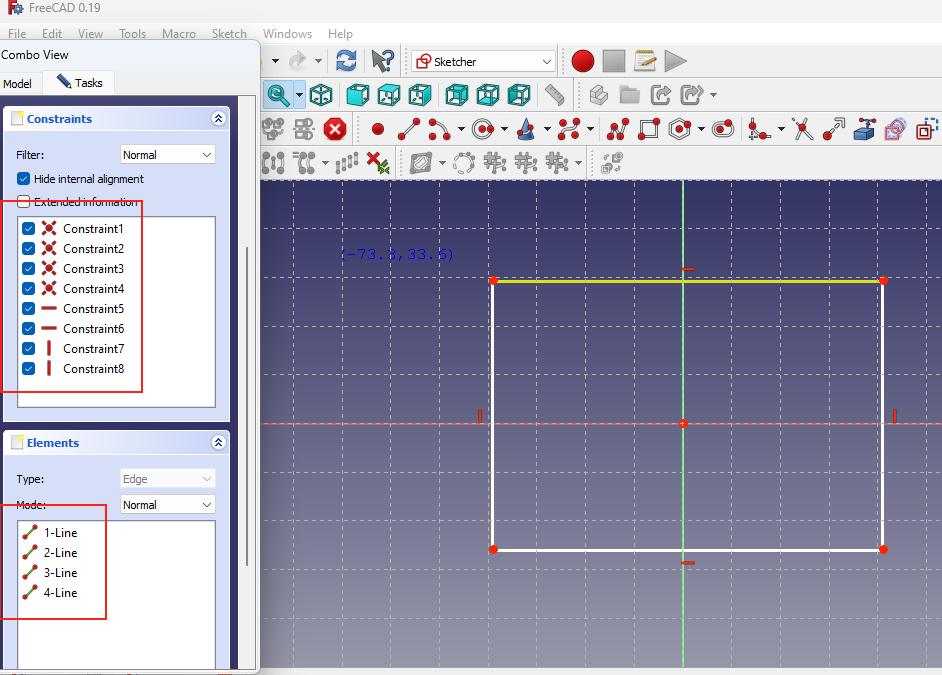
I picked rectangle shape and draw. We can see the the it consist of lines and the point constraints that are connecting lines and the horizontal and vertical constraints which defines that the lines has to be horizontal or vertical always. These constraints define the degree of freedom for the sketch so that it s fully constrained so that we can’t modify it anymore as it is fully defined.
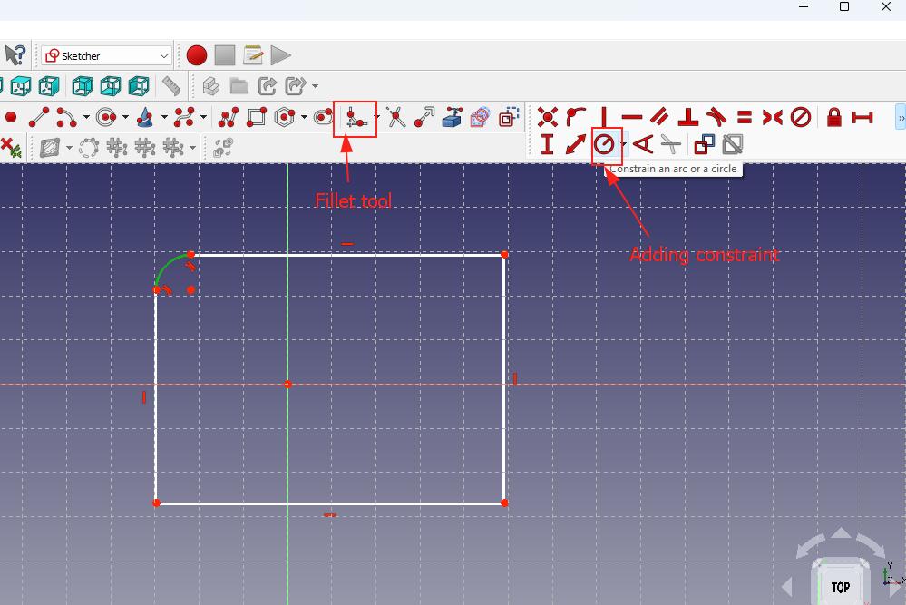
- To add fillet I selected the fillet icon form the tool bar and the clicked on the rectangle corner. To add constraint for this fillet I selected the icon and set the radius of 5mm.
-
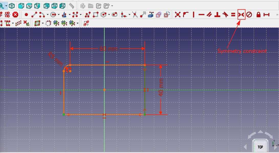
To make it fully constrained we need to add more constraints on lines and points so that the shape is fixed. I set the length of the lines by using horizontal constraints and set to dimension of 60mm. For the vertical line i use the same tool and set 40mm.
-
To define the position in relation to the center select the points and axis and add symmetry constraints for both horizontal and vertical.
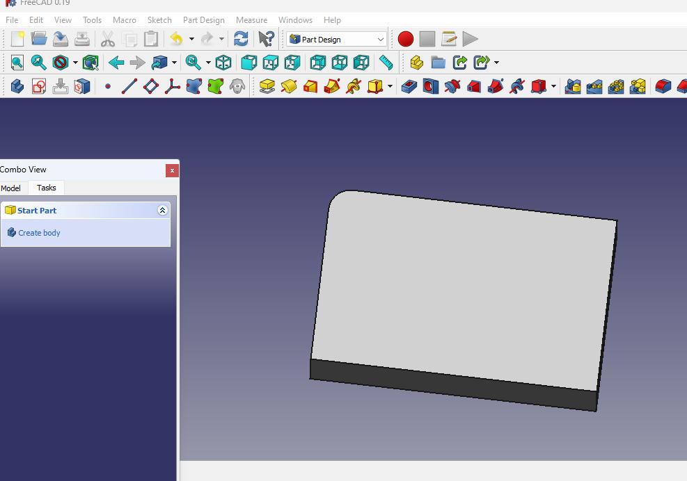
- I closed the and created a pad which is also called extrusion. I made the thickness of 20mm written on the text box and I can see the changes in the view. Similar to Fusion 360 Ican go back to sketch and edit the sketch as well.
Throughout my Fabacademy I decided to use fusion360 for 3D design and modeling because after using it for a year I found it more easier to use tool and features than FreeCAD. In freeCad every time we change the setting we have to close and re-open the software.
Video Compression
FFMPEG
- For compression of video I used FFMPEG as it is free open-source cross-platform software.
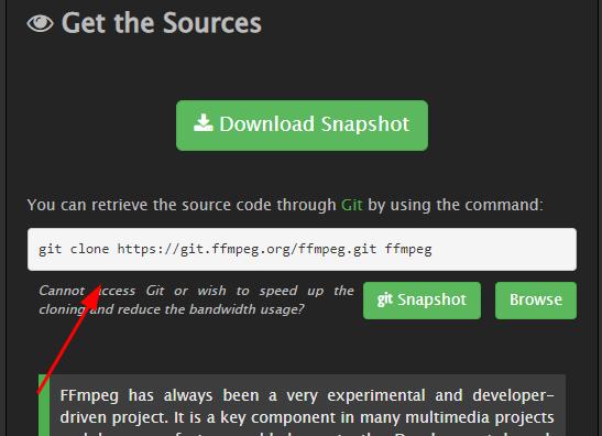
- To download the FFMPEG go to this link FFMPEG. Copy the git clone link paste in terminal and press enter.
-
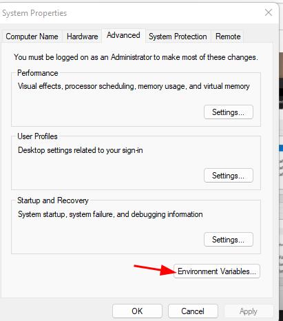
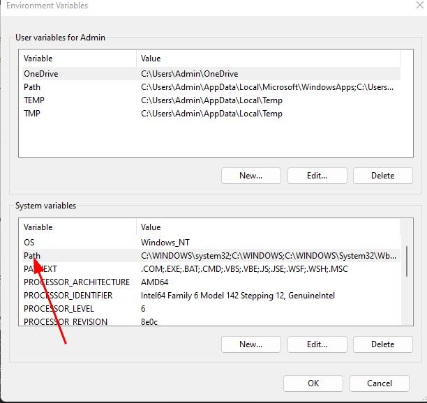
When I tried using FFMPEG it didn’t work. Because I have to set its path and I used the step as below for window user.
-
I searched for Environment variable setting in window browser > Edit environment variable >> Path >> Edit >> New >
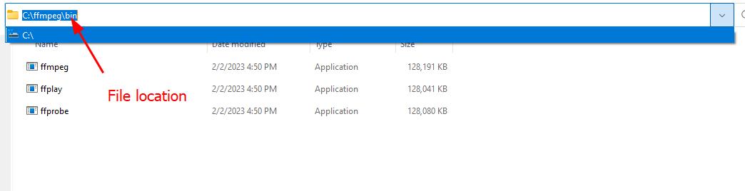
- Paste the file location >> Ok.

Video Compression
- To compress the video I opened the Git bash in the folder where the video is located. Right click> Show more option >> select the terminal.
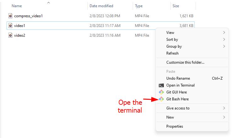
-
When the git bash opens enter this code:
ffmpeg -i video1.mp4-vcodec libx264 -b:v 1000k -vf scale=-2:1080-acodec mp2 -b:a 256k -ar 48000 -ac 2 compressed_video1.mp4.
replace the name of the input and output video according ot its actual name.
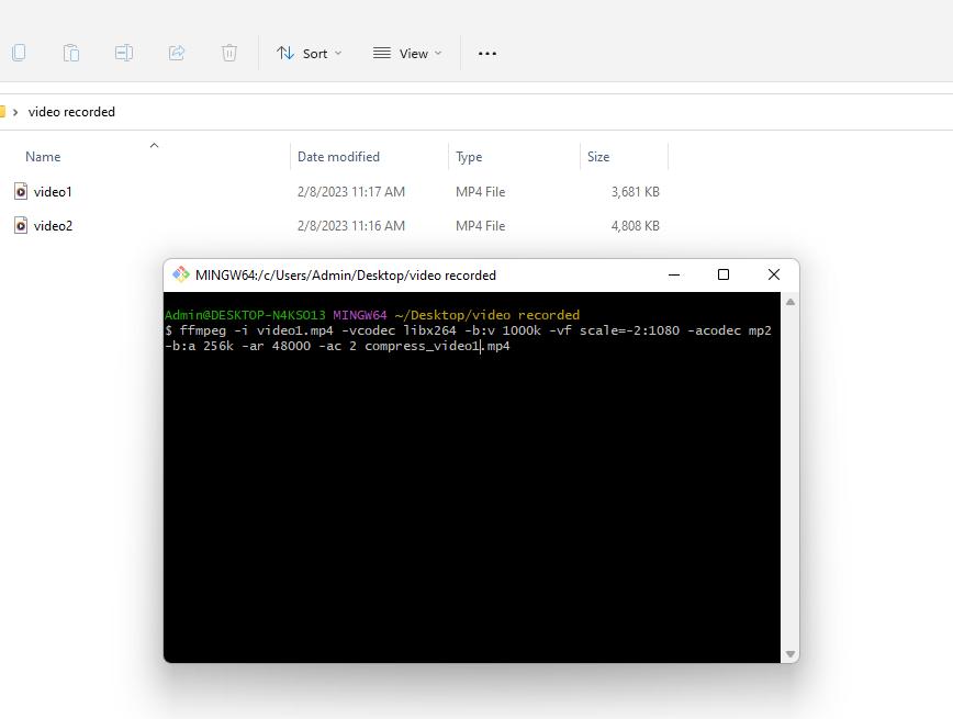
- Video got compressed successfully as shown below.
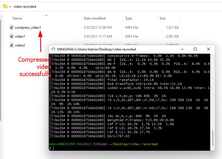
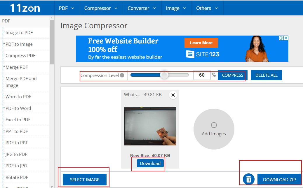
Image compression
To compress the image I use online image convertor from this link It is free, simple and easier as we do not have to install softwares and also it compress the file to smaller size as per requirement without much distortion in file quality.
Design file for this week is here