Electronics Design and Production
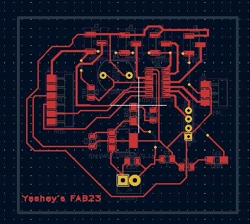
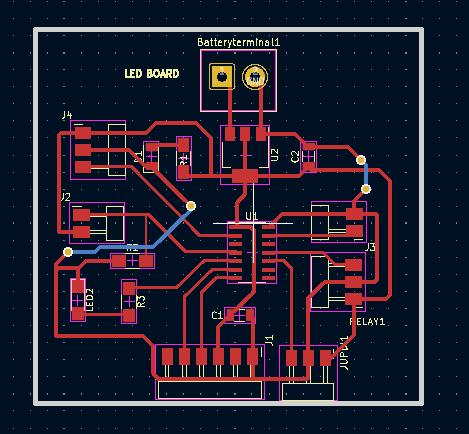
1st version of my board This week I worked on redesigning the board including all the outputs. This is my rough sketch of my PCB schematic layout.
Components
- MCU ATTIny 1614
- Servo motor 3numbers
- LDR sensor
- Capacitor 10uf
- Resistor 10k, 120k
- UPDI
- FTDI
- LED
- Battery 9v
- Voltage regulator AMS1117 5.0 1A
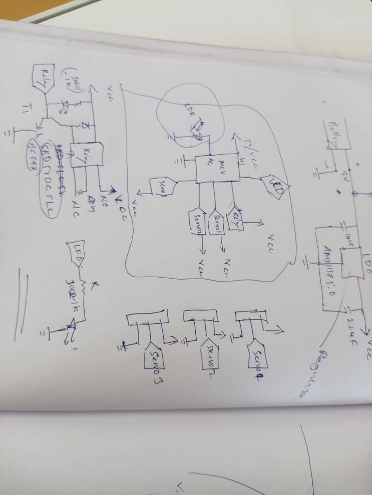
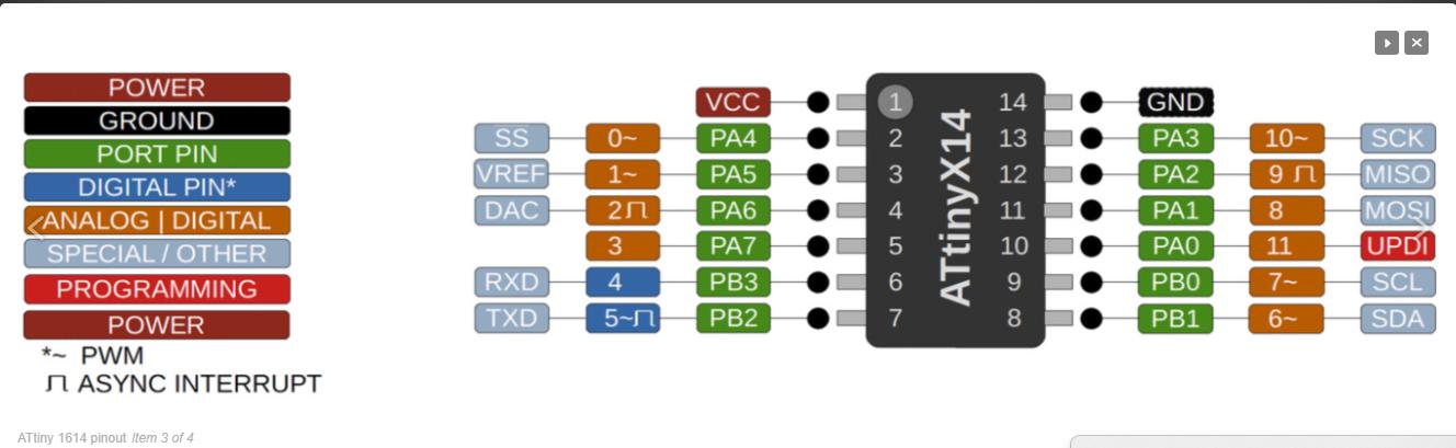
For this I studied study a datasheet for proper connection of the input and output pins.
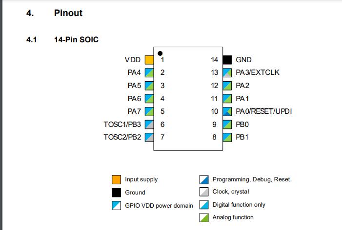
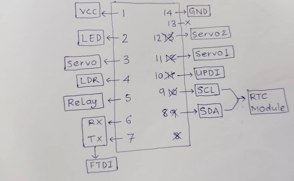
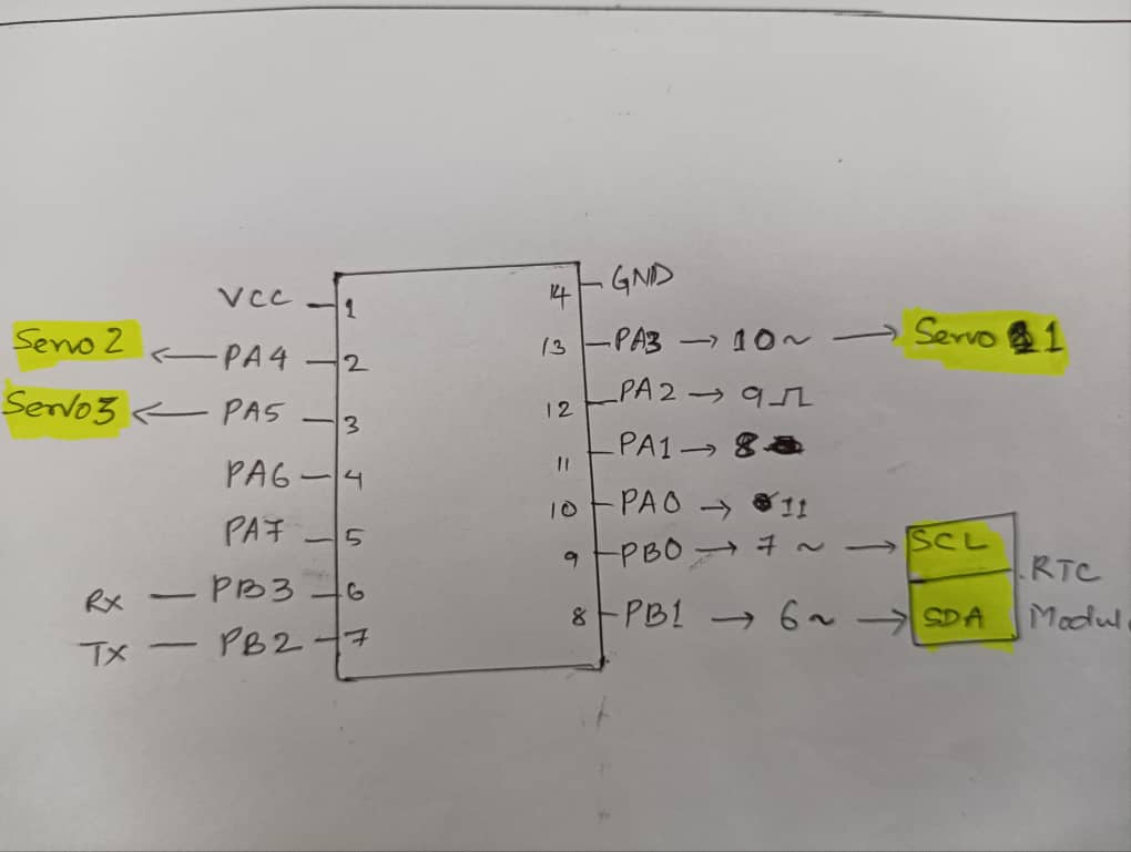
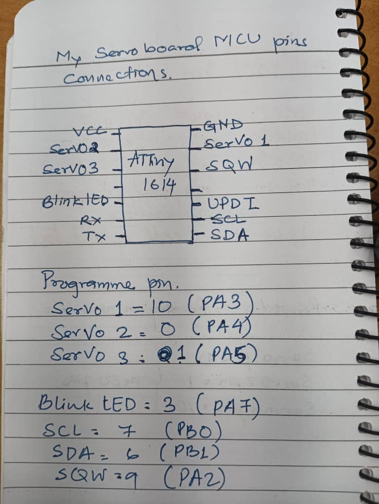
This is the sketch of pin connections of MCU to each components on my board.
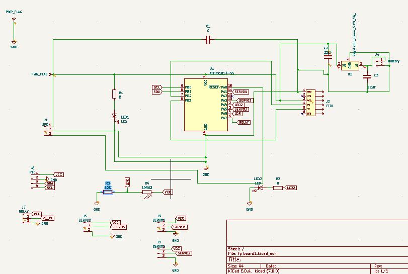
This is my board and I have to mill the board and programme it.
Before milling the board I made a little bit change in board. I made a common ground plane so I do not have to use rivet. I had drills as well because I am using some through hole components.
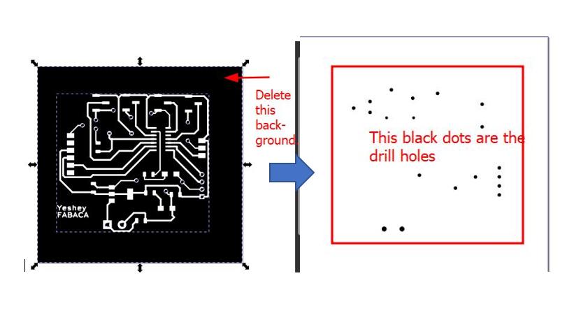
In the electronics design week and electronics production week I didn’t attempt using drill. So this was something new for me. - For drills there is options in Kicad to export the drill file directly. - But I prefer using the inkscape to segregate the hole parts. I can either use layers or ungroup the image and remove the background. I will appear as shown below.
After soldering the components the board is not receiving the power from UPDI so I checked continuity and it continuity is there, but I found out that the Capacitor connection was mistaken for the power LED. When I remove the capacitor it worked but My another mistake was I flipped UPDI pins and mismatched with VCC and programme pin. The power LED is glowing only when I connect the UPDI in flipped position.
The edge cut looks rough because the XY coordinate got disturbed due to power fluctuation and I could not resume the milling process, hence I cut it with hacksaw.
2nd Version of my board
I edited the PCB board remilled the board removing the common ground plane and made same as the first one and I want to use rivet.
This is my soldered board..
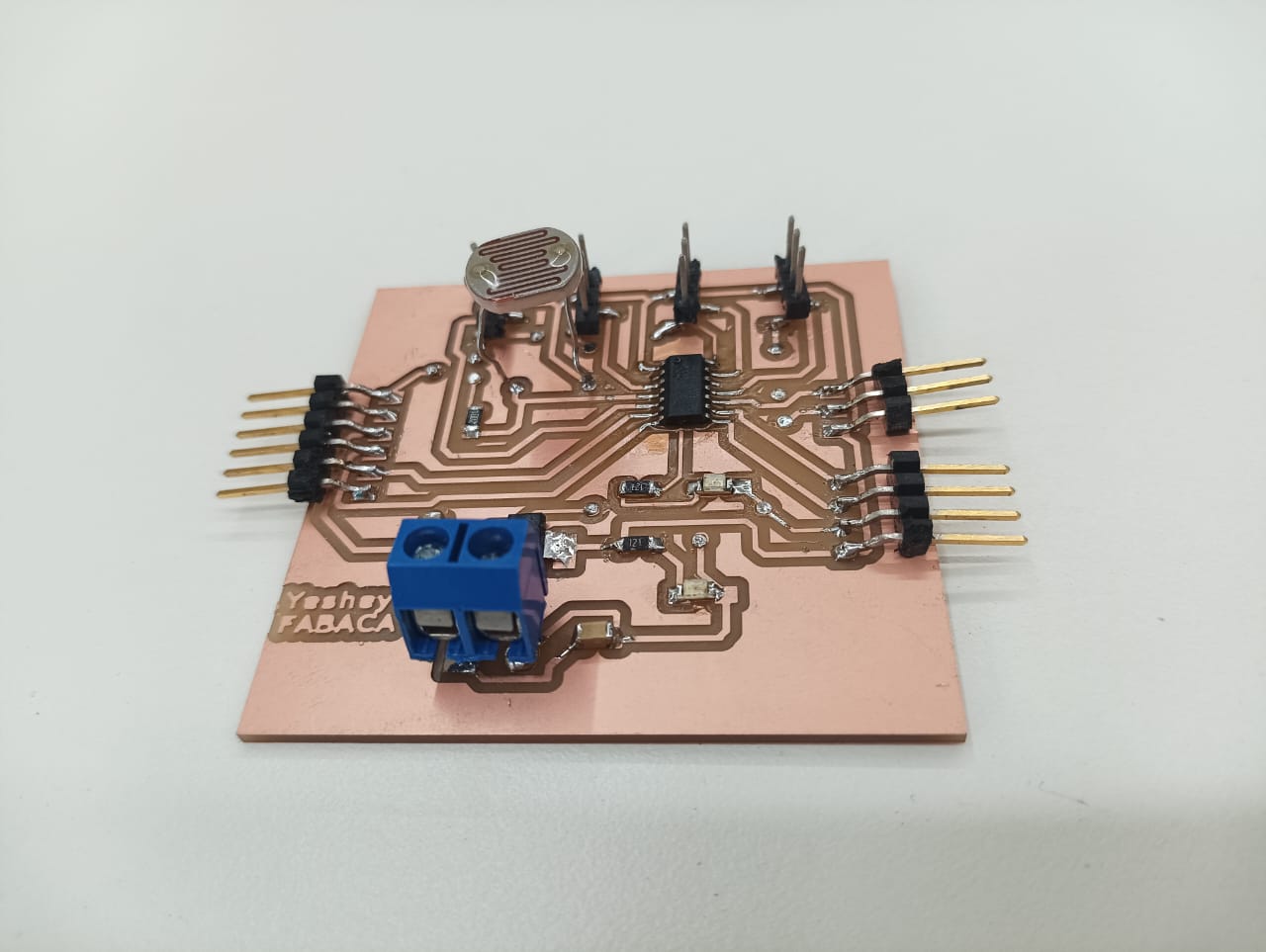
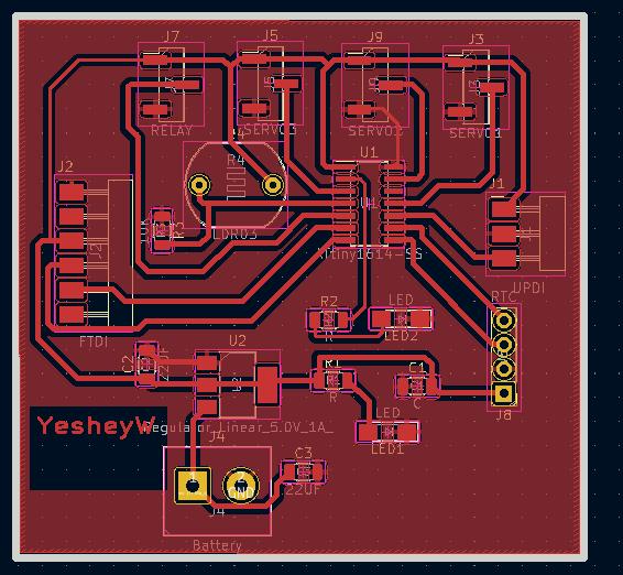
This is the layout of the output and input components on my board.
Splitting the board into two
In today’s class Rico suggested us to keep some pins extra on MCU which was very helpful for me because I had all MCU assigned with each components. To do this I had to make two boards, one for servo motors and ow for LED. I also kept the extra pin for LED if in case I use programmable LED later.
Designing LDR sensor board.
1st version
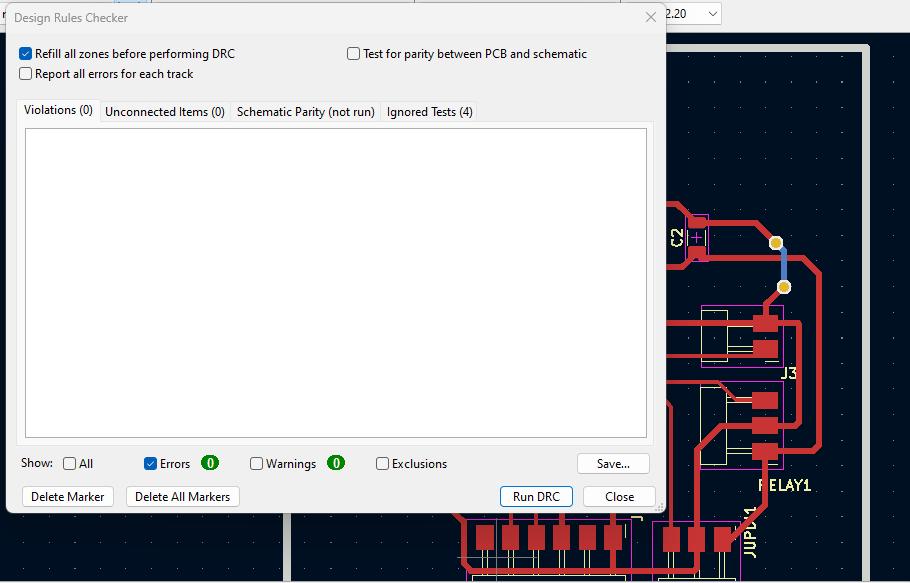
I redesigned my board for controlling LED with LDR sensor. I am happy that this time I did not get error when I run ERC and DRC. Only there was warning with the grid settings. Since my kicad is 7.0 version I couldn’t get the exact setting of grid as I used the older version.
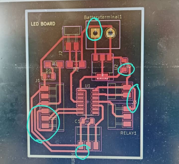
I run the design rule checker and it was fine. This is my PCB Layout.
Redesigning board for Servos
1st Veersion
To design a board for the servo motors I need PWM pins. For three servo motors I need three Pulse Width Modulation pins form ATTiny 1614. I studied the pins as below. In ATTiny 1614 there are 6 PWM pins. This is also one important reason to split board into two. If In use single board there will be specific pin shortage.
This is my Servo location on MCU pins.
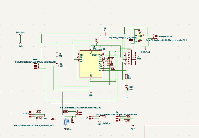
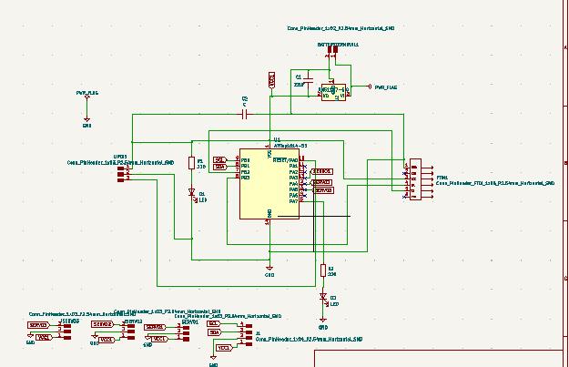
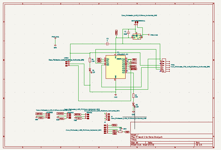
This is my schematic diagram.
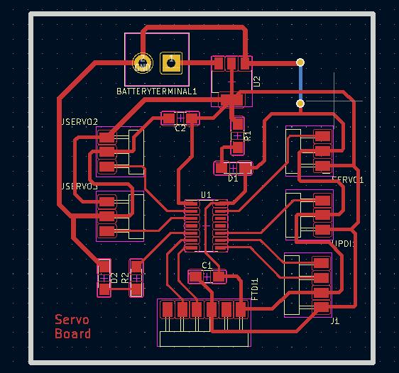
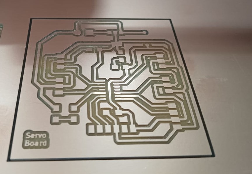
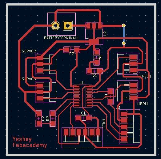
Here is my PCB layout of board for Servo motors.
Milling the LDR sensor board.
Before milling the board I crossed checked with Guru Rico and Zina. As per their feedback I made necessary corrections.
 *
*
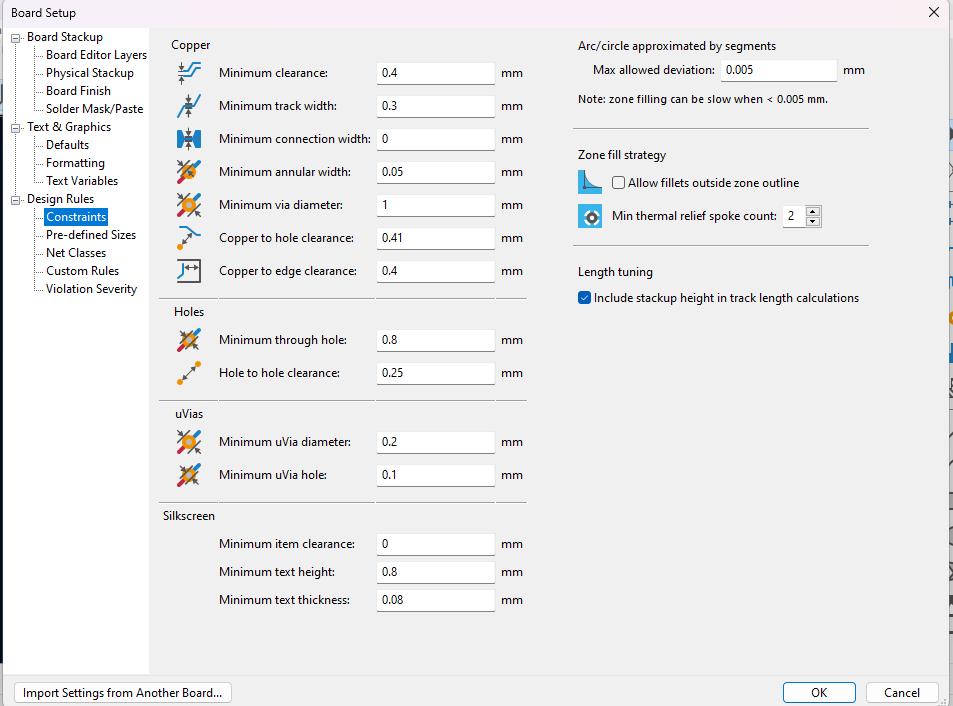
Before drawing the traces I did a board setup. For this I referred the video which is taught us during FabZero session by Fran and Sibu during our lab setup last year.
Here is my corrected board.
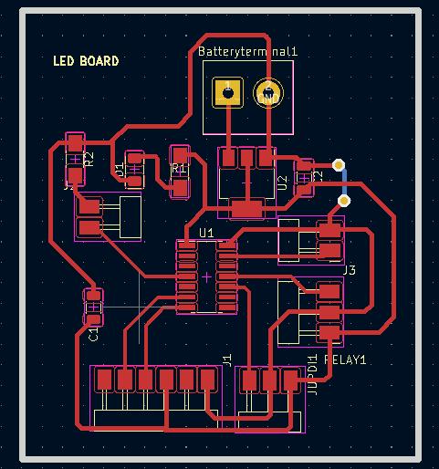
Now the traces are not hugging the pads anymore and there are more defined clearances.
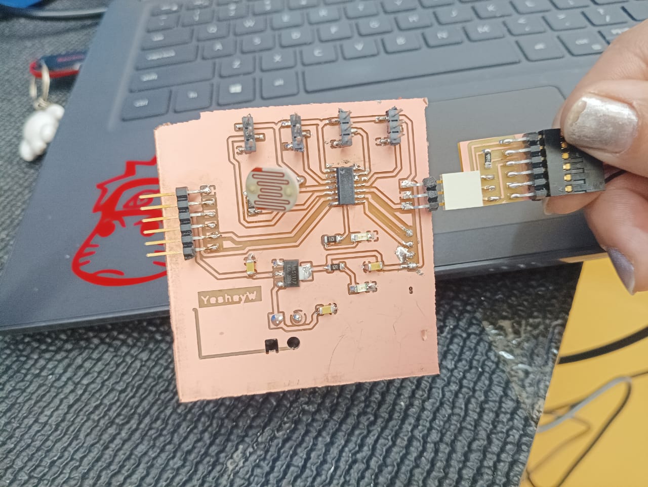
I milled the board and soldered the components and here is hero shot of my board.
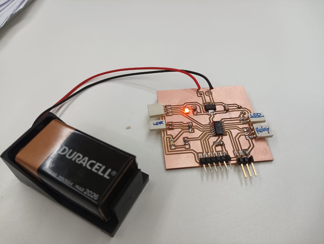 I tested my board firstly with blink LED code and the with LDR sensor it is here.
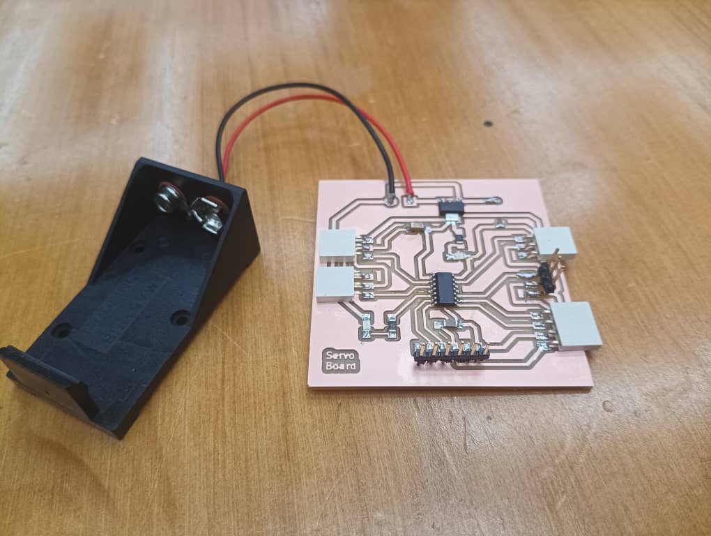
For the servo board I got a feedback to just to change the track width. I kept 0.6mm for VCC and GND and 0.4mm for signal pins. I proceeded on milling the servo board and soldered the board.
Milling the Servo Board
 .
.
When I power my board I noticed the MCU pins are receiving the power and when I tried uploading the programme it says UPDI initialization failed.
 .
.
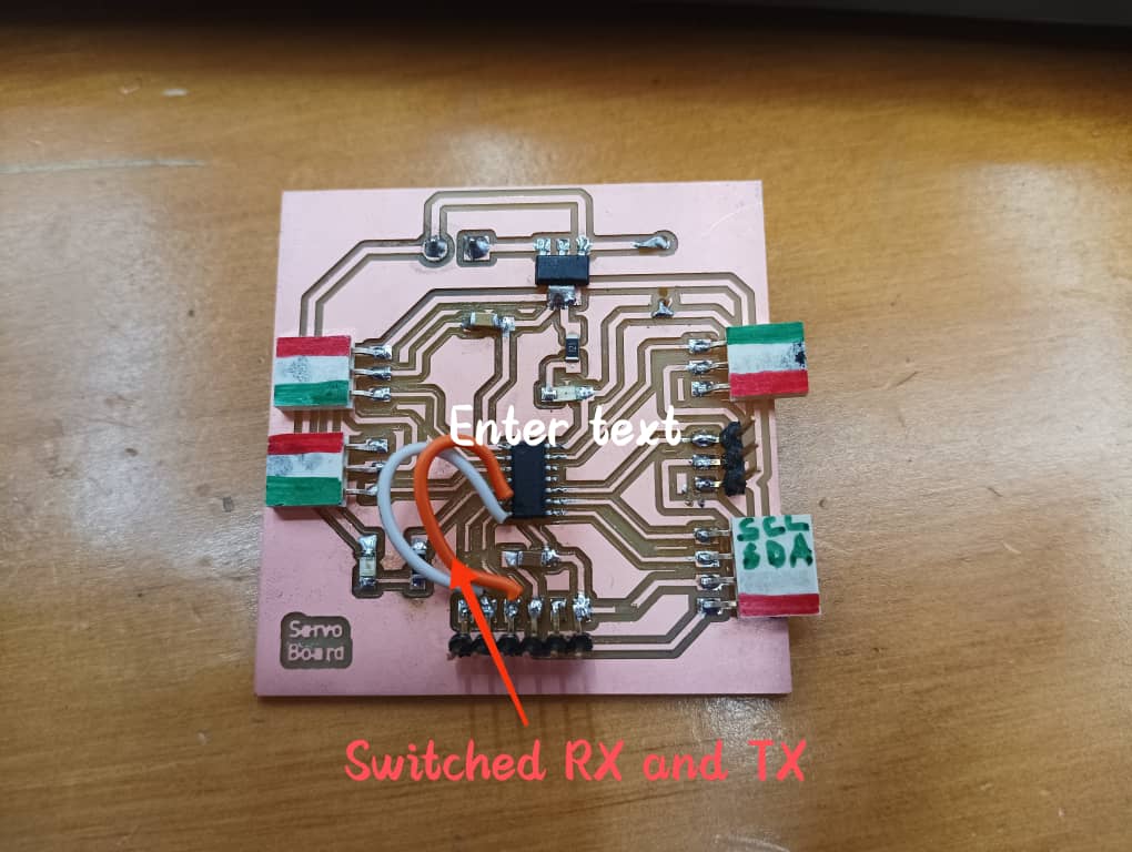
Along with Guru Rico we identified the problem. We checked continuity but its fine. We desoldered the board and removed some pads beneath the components that may cause the bridging. We also noticed that some RX and TX is not switched. Used a jumper wires to switched RX and TX and soldered all the components again.
 .
.
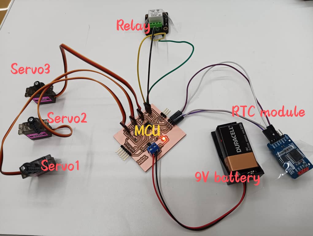
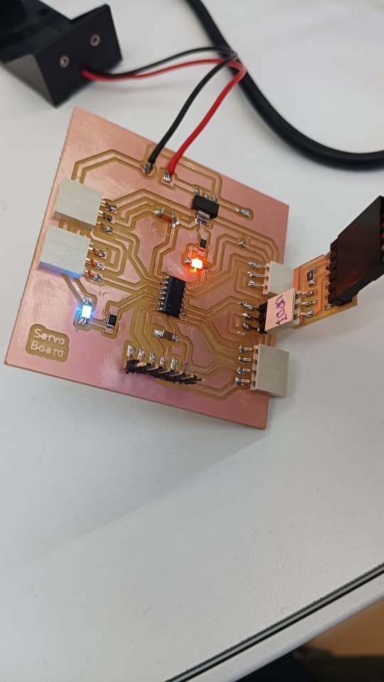
I tested the board and it worked. I did with blink LED test, servo motor taste and with RTC module. The testing part is linked here.
2nd Version of my board
I redesigned the board because I need a extra pin for RTC module for integrate alarm function. I think this will be my final board.
 .
.
 .
.
Here is the PNG file for Traces and edgecut.
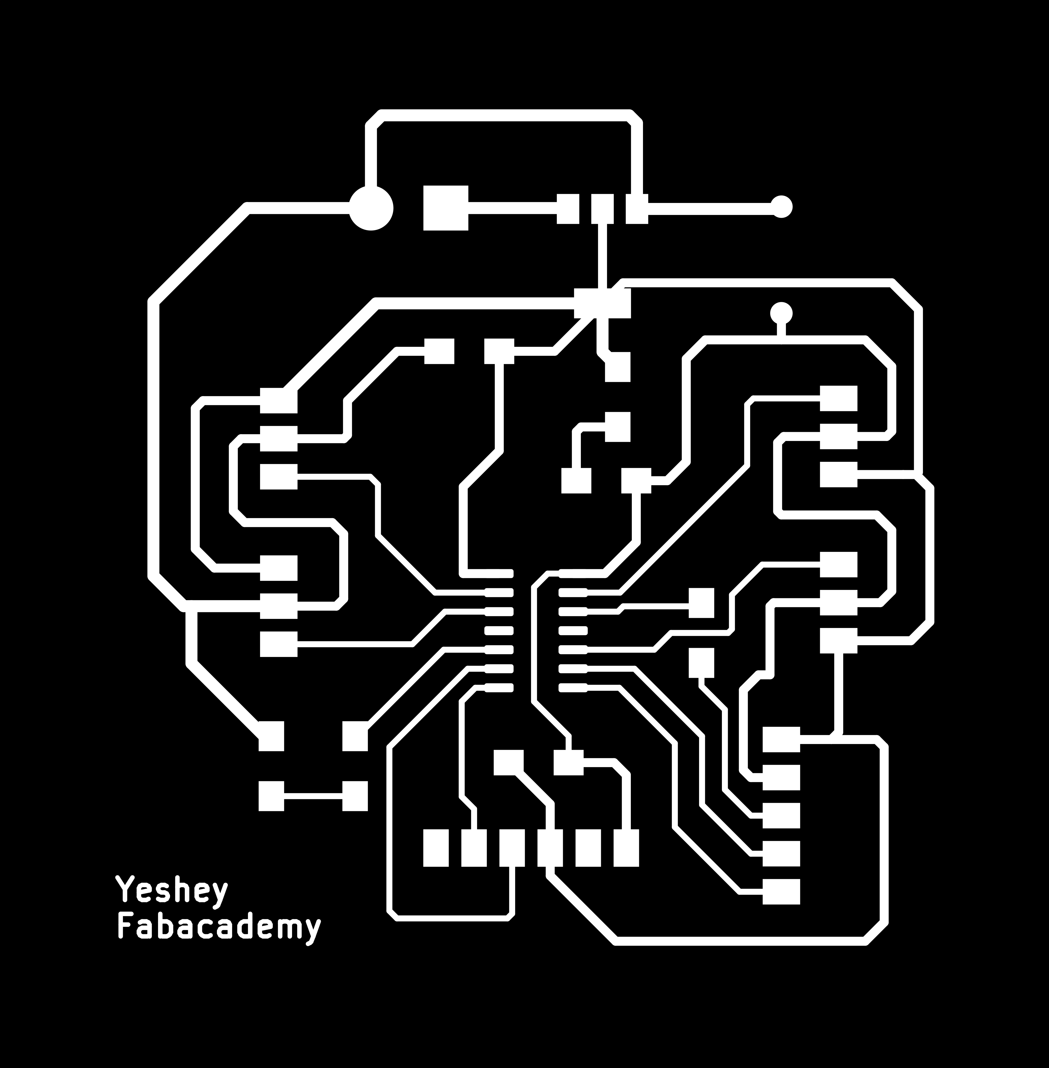
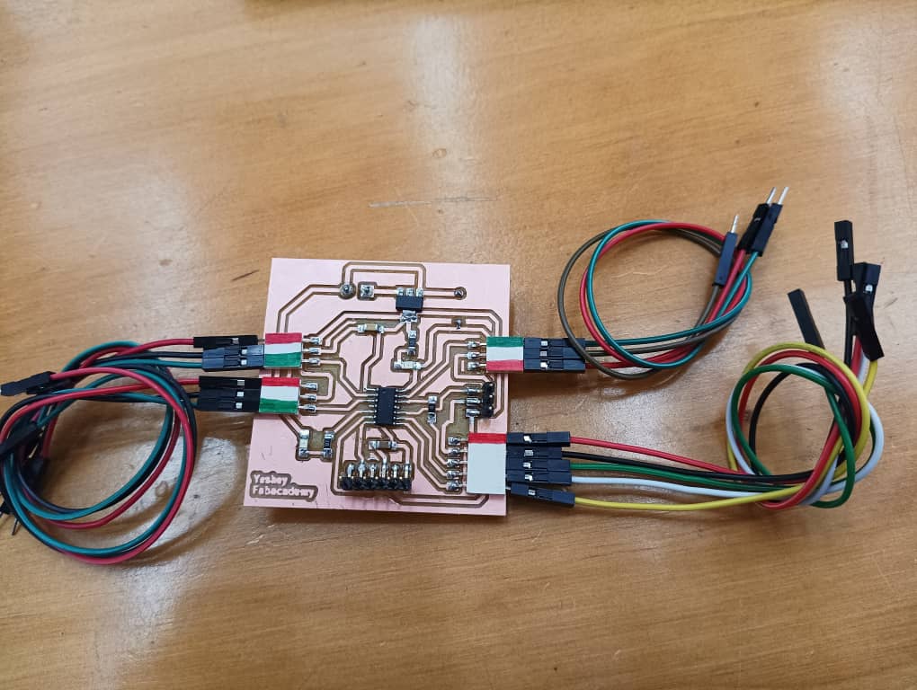
I milled the board and soldered the board. THis time our solder us better and looks shinny as Guru Rico taught us to us flux which helps the lead melt better and shine.
Here is the hero shot of my board.
 .
.